Thermal conductivity is a measure of how well or poorly a material conducts heat energy (measure of the strength of heat conduction)!
Thermal conduction
In general, heat can be transferred in three different ways (for more information on the different types mentioned below, see the article Heat transfer):
- by thermal convection,
- by thermal radiation and
- by thermal conduction.
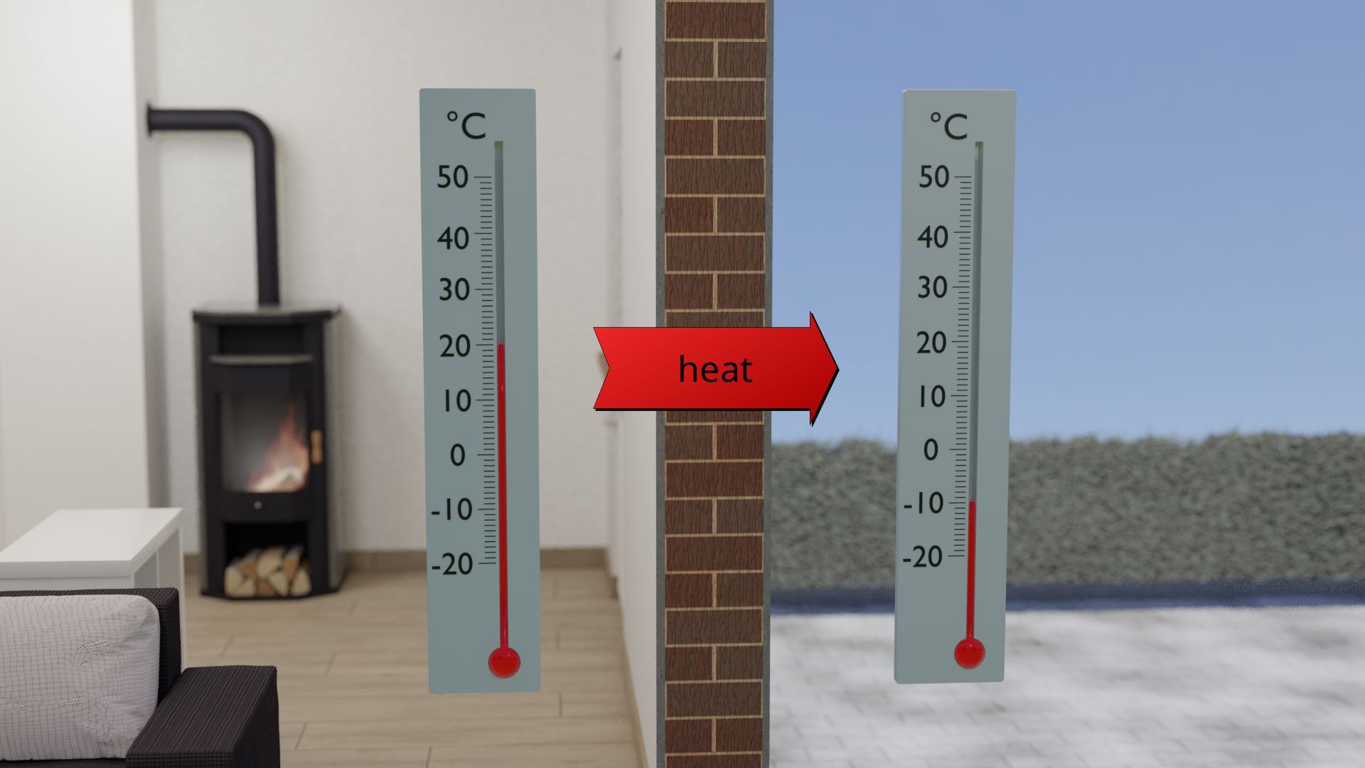
Especially in solids, heat conduction is of great technical importance, but also in thin gases at elevated temperatures, heat conduction predominates over thermal radiation and convection. Thus, for example, house walls or insulation panels foamed with air should only conduct heat to a small extent. This ensures that in winter only a small amount of heat penetrates the building walls to the outside. This prevents the building from cooling down too quickly. But this has also the advantage that, with low heat conduction, only a small amount of heat penetrates into the building from the outside in summer. In this way, the inside of the building remains pleasantly cool.
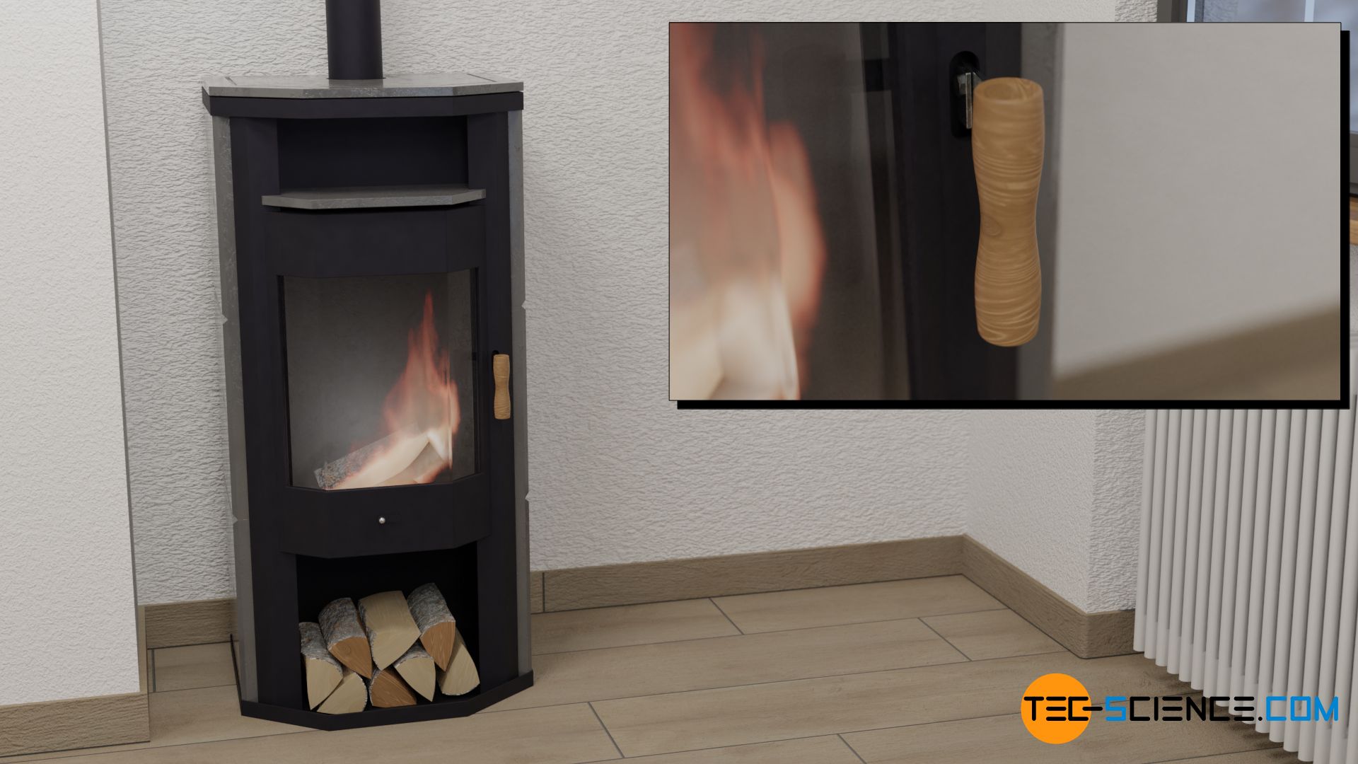
Due to the special importance of heat conduction, it will therefore be characterized in more detail in the following. Everyday experience already shows that different materials conduct heat better than others. Metals are generally very good heat conductors, whereas plastic or wood usually conduct heat only to a lesser extent. For this reason, handles on hot metal objects such as oven doors, for example, are made of wood (see also the article Human thermal response). For the same reason, metal kettles usually have a plastic handle.
Independent of the material, the first question that arises is what other parameters influence how much heat a material conducts.
Influence of the temperature difference
In order for a heat flow to occur at all, a temperature difference must first be present on the object. To stay with the example of the building wall, the reason for the heat flow is the temperature difference between the inside of the building and the environment.
Practice shows that the greater the temperature difference, the more heat flows through the building wall. This is also the reason why more heating is required in winter than in autumn or spring. Because of the greater temperature difference in winter between the inside and outside of the wall, the heat flow through the wall is greater than in spring, when the temperature difference is smaller. If the temperature difference is zero, i.e. the outside air has the same temperature as the air inside the building, then there is no need to heat at all. As a result, no heat penetrates through the wall to the outside.
The heat flow through an object is all the greater, the greater the temperature difference from one side of the object to the other!
More detailed analysis shows that the rate of heat flow Q* through an object is almost proportional to the temperature difference ΔT. A multiplication of the temperature difference therefore means an equally increased heat flow:
\begin{align}
&\dot Q \sim \Delta T \\[5px]
\end{align}
Influence of the thickness of the material
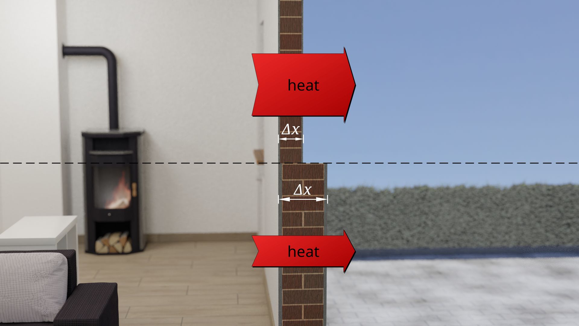
Furthermore, the thickness of the object influences the heat flow. Even here, everyday experience shows that the thinner the object, the greater the heat flow through it. Conversely, of course, this means that the thicker the material, the lower the heat flow. This is why, in winter, you put on a thick jacket instead of a thin one.
The influence of the material thickness on the heat flow is also clearly evident in building walls. Thick walls allow the building to cool down less quickly than relatively thin building walls. The heat flow through a thick wall is obviously lower than through a thin one.
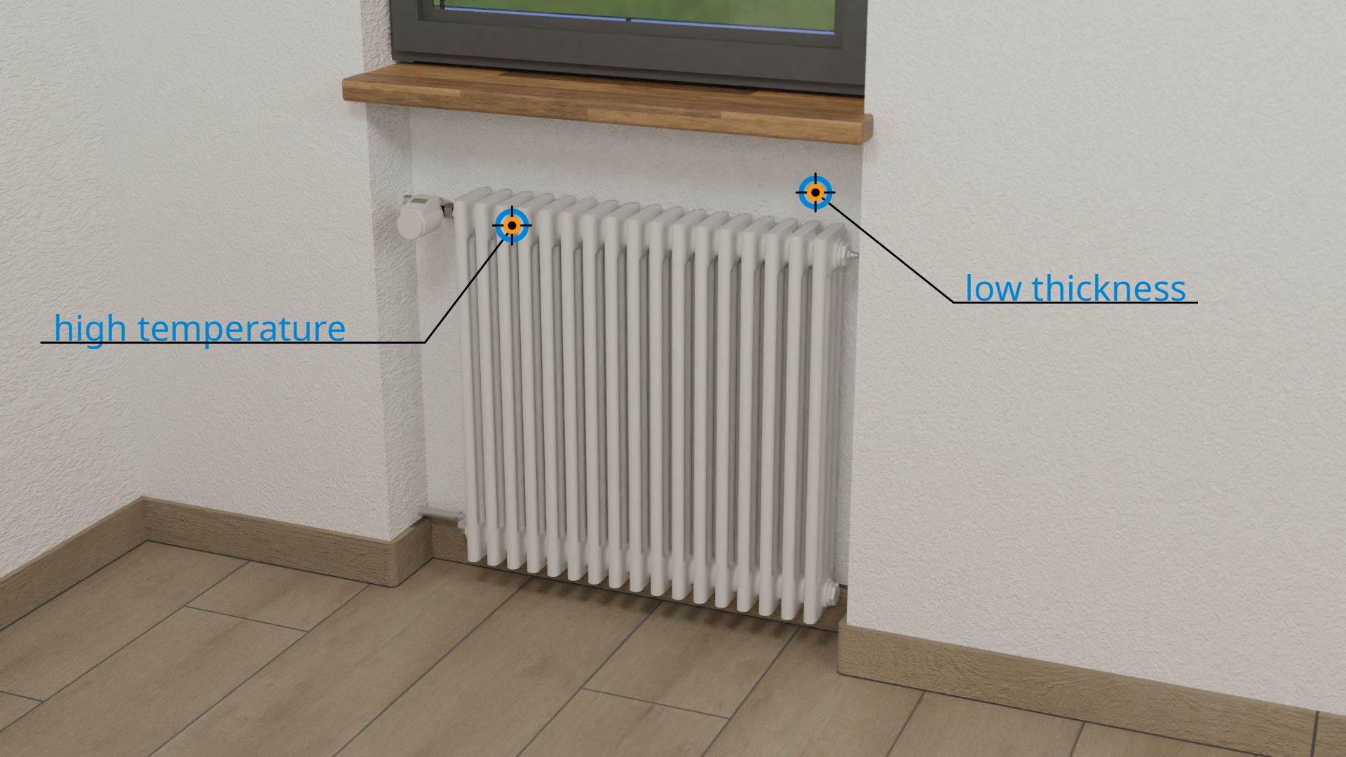
Radiators in older buildings, which for optical reasons are somewhat recessed into the building walls (radiator niches), are therefore very unfavorable in two respects for energetic reasons. On the one hand, the building wall is relatively thin there, which already causes a large heat flow. On the other hand, the heating system is also located there, i.e. there is a very high temperature on the inner wall. The temperature difference between inside and outside is also relatively high, which increases the outgoing heat flow even more! The installation of reflective foil behind the radiator brings (contrary to what many manufacturers claim) almost no perceptible insulation effect. Reflective foil only helps against thermal radiation, but not against the far greater effect of heat conduction!
The heat flow through a heat-conducting object is the smaller the thicker the object is!
More detailed examinations show that doubling the material thickness means halving the heat flow. Heat flow Q* and material thickness Δx are thus reciprocal to each other:
\begin{align}
&\dot Q \sim \frac{1}{\Delta x} \\[5px]
\end{align}
Influence of the surface area of the material
The heat flow is also directly dependent on the area through which the heat flow passes, i.e. the cross-sectional area perpendicular to the direction of the heat flow. In the case of a building wall, this is the area of the wall. The larger the area, the more heat can pass through the surface or object. Consequently, the heat flow is also relatively high for large surfaces. Therefore, heating costs are generally higher for buildings with many large windows (which usually conduct the heat better than the building walls) than in buildings with only a few small windows. A lot of heat penetrates through the large window area, i.e. the heat flow through it is relatively high.
The heat flow through an object is the larger the larger the cross-sectional area of the material!
The reduction of a heat flow by a reduction of the surface area is unconsciously also apparent in us humans. The crouching of the body in cold weather is exactly such an instinctive behavior, which is based on the principle of reducing the surface area. Of all geometric shapes, the sphere has the smallest possible surface area in relation to its volume and is therefore extremely favorable from an energetic point of view. By cowering together one tries to take on the shape of a sphere. With this one is trying to create the smallest possible surface area in contact with the cold environment. In this way one achieves a low heat flow and the body stays warm longer.

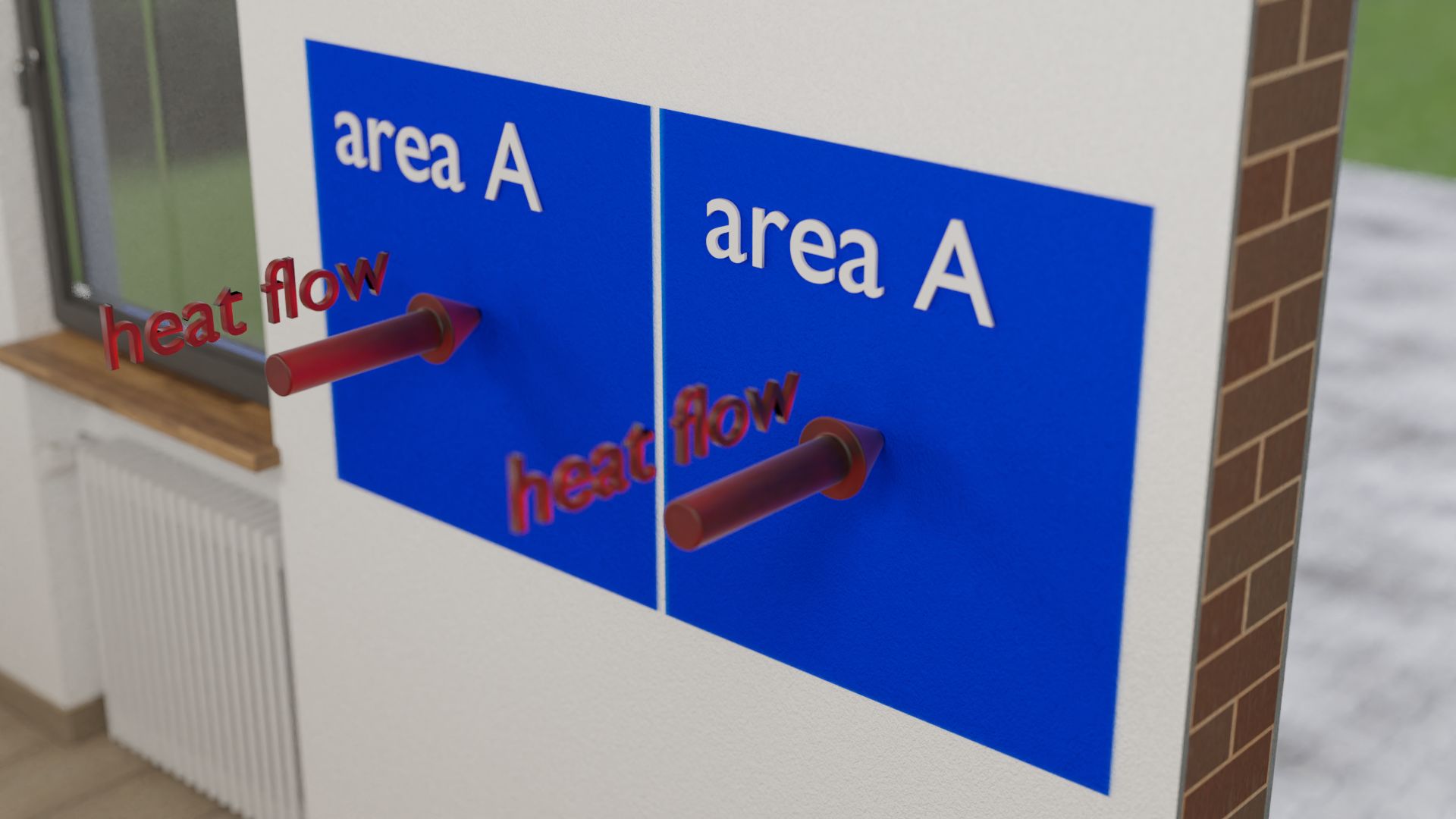
A closer look shows that the heat flow is proportional to the surface area. This can be easily understood. For example, one can imagine two identical surfaces on a building wall. The same heat flow passes through both surfaces. Now, in your mind you take both surfaces together to form one large one, i.e. you double the surface. Obviously, twice the heat will then flow through twice the area. So the heat flow and the area are proportional to each other:
\begin{align}
&\dot Q \sim A \\[5px]
\end{align}
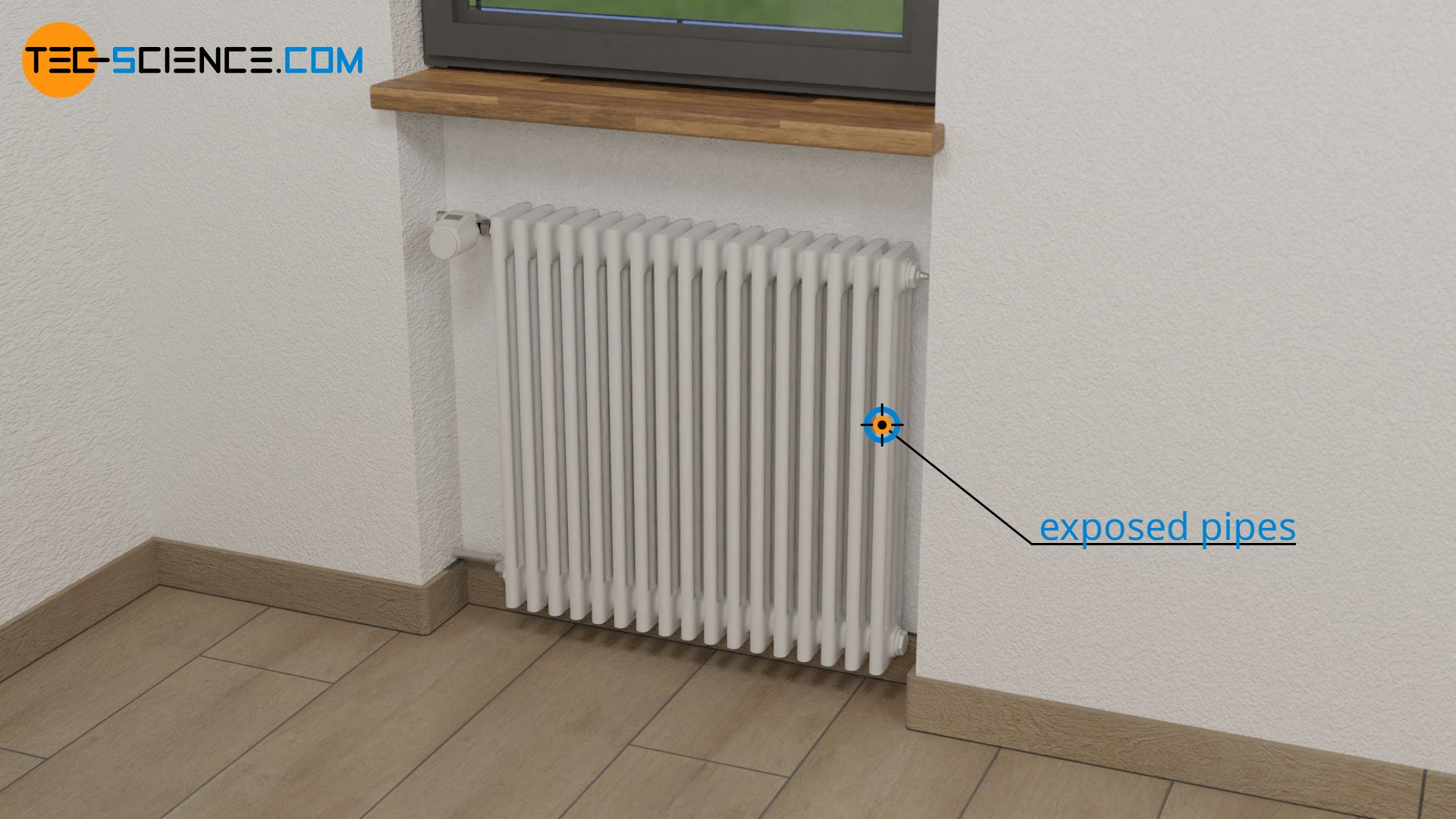
The increased heat flow through larger surfaces is used for example for radiators. For this reason, radiators are usually not built in one big flat piece, but consist of many exposed pipes. This increases the surface area, which leads to an overall greater heat flow. The apartment gets warm faster.
The operating principle of cooling fins is also based on the increase in surface area and the correspondingly higher heat flow. Only that in this case heat is not supplied but dissipated. This means that the object can be cooled more quickly. The figure below shows the use of cooling fins to cool the chip of a graphics card (GPU).

Fourier’s law
As the relationships described above show, the heat flow Q* through a material is thus proportional to the temperature difference ΔT and proportional to the area of the material A, and inversely proportional to its thickness Δx. This can be represented as follows:
\begin{align}
\dot Q &\sim \frac{\Delta T \cdot A }{\Delta x}\\[5px]
\end{align}
This relation applies independently of the material, i.e. for any material the heat flow will be proportional to the temperature difference and to the surface area and reciprocal to the thickness. However, by introducing a material-dependent proportionality constant λ this relation can finally be formulated as an equation. This equation is also known as Fourier’s law.
\begin{align}
\label{q}
&\boxed{\dot Q =\lambda \cdot \frac{\Delta T \cdot A }{\Delta x}} ~~~~~\text{and}~~~~~[\lambda]=\frac{\text{W}}{\text{m} \cdot \text{K}} ~~~~~\text{thermal conductivity}\\[5px]
\end{align}
Fourier’s law describes the heat flow that passes through a material by heat conduction!
The proportionality factor λ in the above equation is called thermal conductivity and is largely determined only by the material of the object. The thermal conductivity is expressed in the unit W/(m·K) (“watt per meter and kelvin”). A thermal conductivity of e.g. 2.4 W/(m·K) means that with at a material thickness of one meter a heat flow of 2.4 watt (i.e. 2.4 Joules per second) passes through an area of one square meter if the temperature difference is one Kelvin.
Thermal conductivity is a measure of how well or poorly a material conducts heat energy. (“measure of the strength of heat conduction”)! It applies only to the heat transfer by thermal conduction, not convection or radiation!
Fourier’s law applies in this form only if the surfaces through which the heat passes are plane and parallel to each other. In reality, however, the thermal conductivity is not a pure material constant, but depends on the temperature. At large temperature differences, the thermal conductivity can therefore change relatively strongly over the thickness of the material. In these cases, one has to use the mean value of the thermal conductivity.
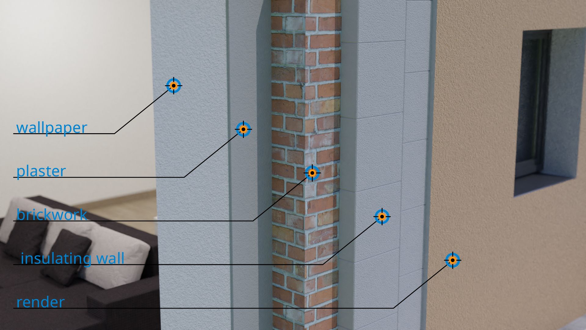
It should be noted again that the thermal conductivity only describes the heat transfer by heat conduction inside a material. Heat transport at the interface due to thermal convection are not considered. When heat is transported through a building wall, there are generally many different materials that affect the overall heat transfer. From the inside to the outside this could be for example: wallpaper → plaster → brickwork → insulation wall → render. Such heat transfer through materials and their interfaces are discussed in more detail in the article Thermal transmittance (U-value).
Information on the experimental determination of thermal conductivity can be found in the linked article.
Heat flux & temperature gradient
Equation (\ref{q}) describes the heat flow as a function of geometric quantities of the material such as area and thickness. By rearranging this equation, however, these geometric dependencies can be easily eliminated:
\begin{align}
\dot Q &= \lambda \cdot \frac{ \Delta T }{\Delta x} \cdot A \\[5px]
\label{u}
\underbrace{\frac{\dot Q}{A}}_{\text{heat flux } \dot{q}} &=\lambda \cdot \underbrace{\frac{\Delta T}{\Delta x}}_{\text{temperature gradient }\nabla{T}} \\[5px]
\end{align}
The quotient of heat flow and area describes the heat flow per unit area. It can thus be interpreted as heat flow density, which is also referred to as heat flux q* (thermal power per unit area).
Heat flux is the thermal power per unit area!
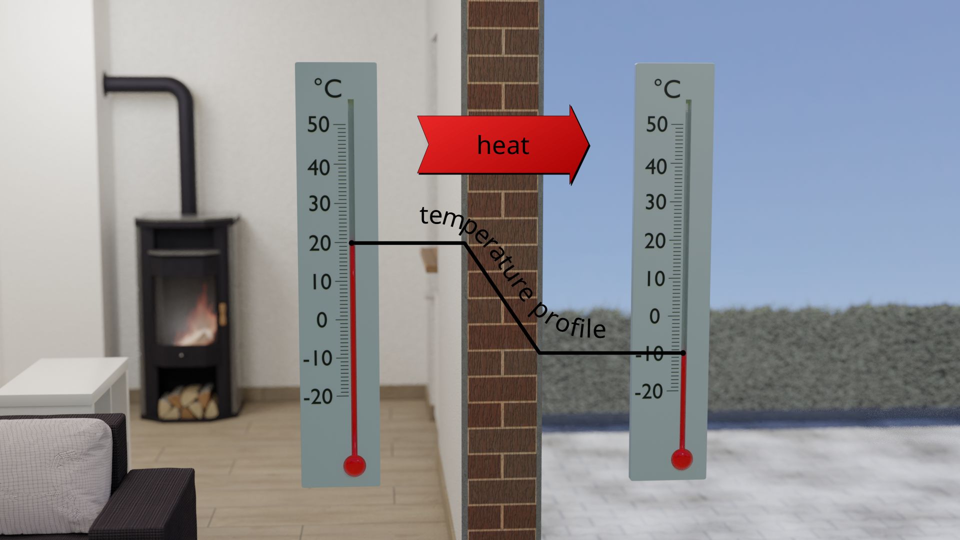
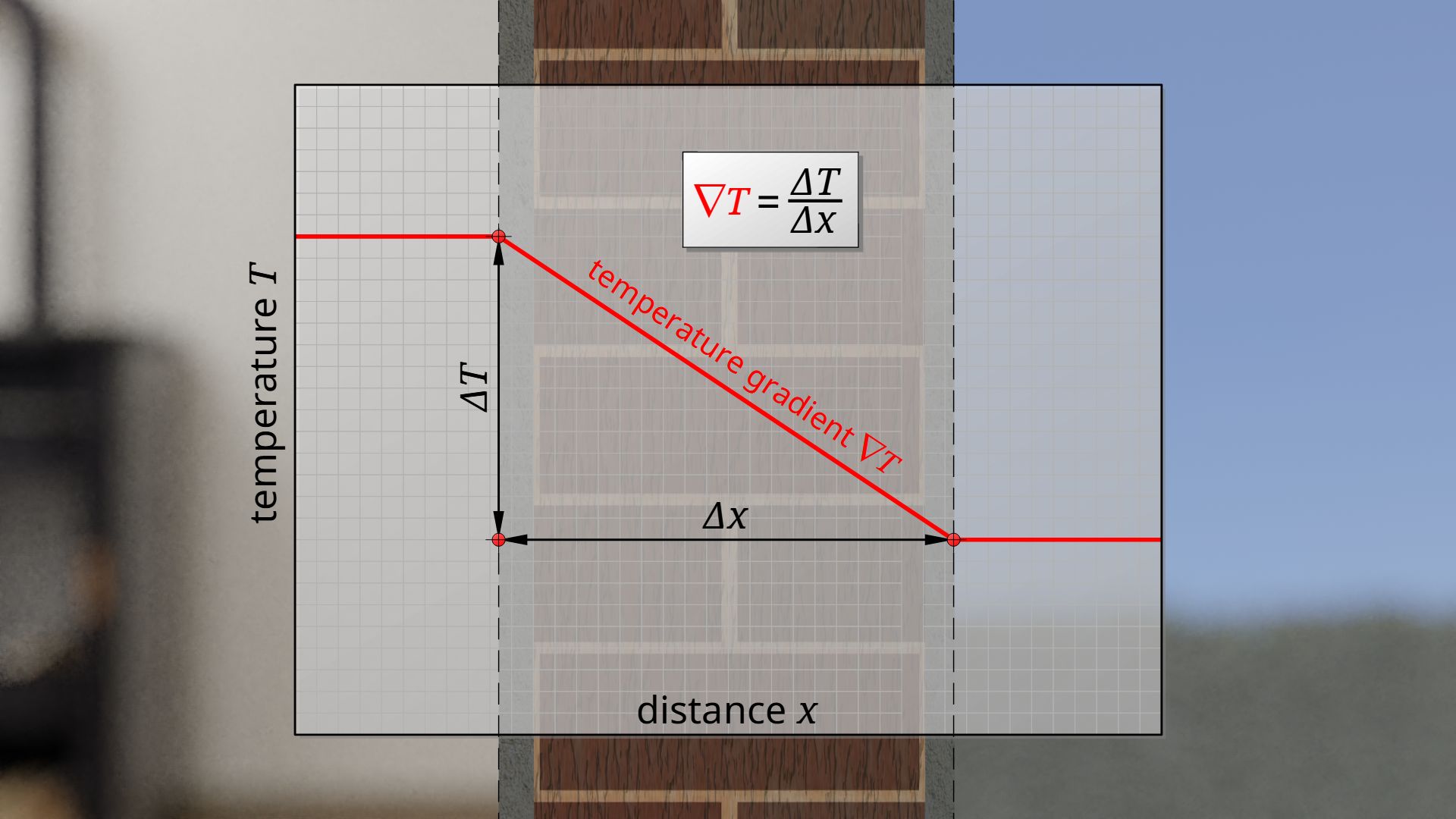
The quotient of temperature difference and material thickness can also be clearly interpreted. This quotient ultimately describes the drop in temperature per unit length. Such a spatial change of a quantity along a distance is generally referred to as a gradient. In this case the temperature drop is called temperature gradient ∇T. The temperature gradient corresponds to the slope of the temperature profile. A gradient is usually denoted by an upside down Greek Delta (also called del or nabla).
The temperature gradient is the temperature change per unit length!
For a correct mathematical characterization, a minus sign must be added to equation (\ref{u}) (and actually also to equation (\ref{q})), because the heat always flows in the direction of decreasing temperature. The heat flux is therefore directed from warm to cold, i.e. in the direction of the negative temperature gradient.
\begin{align}
\label{r}
&\boxed{\dot{q} = -\lambda \cdot \nabla{T}}
\end{align}
In this context, the thermal conductivity of a material thus describes the relationship between an existing temperature gradient and the resulting heat flux. The thermal conductivity of 2.4 W/(m·K) already mentioned as an example can therefore also be interpreted as follows: At a temperature gradient of 1 K/m a heat flux of 2.4 W/m² passes through the material. In this interpretation, neither the surface area nor the thickness of the material plays a role. These quantities are already “included” in the heat flux and the temperature gradient, so to speak. The above equation is therefore independent of geometrical properties!
Also the statement often heard in this context, that Fourier’s law only applies to one-dimensional heat flows with plane, parallel surfaces, is irrelevant in this context. Such a limitation applies only to the equation (\ref{q}), which describes the heat flow on a macroscopic scale, but not to equation (\ref{r})! Equation (\ref{r}) makes a statement about the heat flow density in a single point of a material depending on the temperature gradient there. Any surface has no relevance at all in such a point. Equation (\ref{r}) forms the basis for the heat equation, which also describes three-dimensional heat flows in arbitrarily shaped bodies with non-parallel surfaces.
Thermal conductivity of selected materials
The tables below show a selection of different materials and their thermal conductivity (see Wikipedia and energie-lexikon). The values given refer to a temperature of 20 °C. It can be seen that solids and especially metals have relatively high thermal conductivities, whereas polymers mostly have lower coefficients. Even lower values are generally found with liquids, which are only beaten by gases. The differences are mainly due to the characteristic atomic structure. More about this in the article Heat transfer by thermal conduction.
The thermal conductivity generally decreases from metals, polymers and liquids to gases!
What is striking about metals is the relatively high thermal conductivity of copper. This is why copper is often used, for example, as a material for building cooling elements such as PC coolers. Heat can thus be dissipated very quickly from the heat source. Silver would have an even higher thermal conductivity, but is much more expensive.
| Metals | Thermal conductivity [W/(m·K)] at 20°C |
| Silver | 429 |
| Copper | 401 |
| Gold | 314 |
| Aluminium | 236 |
| Tungsten | 170 |
| Magnesium | 156 |
| Brass | 120 |
| Zinc | 110 |
| Nickel | 85 |
| Iron | 80 |
| Platinum | 71 |
| Steel | ~50 |
| Lead | 35 |
| Titanium | 22 |
| More solids | Thermal conductivity [W/(m·K)] at 20°C |
| Graphene | 5300 |
| Diamond | 2300 |
| Aluminium Nitride | ~200 |
| Silicon | 148 |
| Corundum | 42 |
| Aluminium oxide | 28 |
| Ice (-10°C) | 2,3 |
| Concrete | 2,0 |
| Chalk | 1 |
| Sand limestone | ~1 |
| Autoclaved aerated concrete (AAC) | 0,2 |
| Wood | ~0,15 |
| Polymers | Thermal conductivity [W/(m·K)] at 20°C |
| Polyethylene | ~ 0,45 |
| Polytetrafluorethylene (“Teflon”) | 0,25 |
| Polyurethane (unfoamed) | 0,25 |
| Polypropylene | 0,23 |
| Epoxy resin (EP) | 0,20 |
| Polymethylmethacrylat (Plexiglas) | 0,19 |
| Polyvinyl chloride (PVC) | 0,17 |
| Polystyrene (unfoamed) | 0,17 |
| Liquids | Thermal conductivity [W/(m·K)] at 20°C |
| Water | 0,60 |
| Sulphuric acid | 0,54 |
| Alcohol | 0,17 |
| Gasoline | 0,14 |
| Oil | 0,14 |
| Gases | Thermal conductivity [W/(m·K)] at 20°C |
| Hydrogen | 0,186 |
| Helium | 0,157 |
| Methan | 0,034 |
| Oxygen | 0,026 |
| Air | 0,026 |
| Nitrogen | 0,026 |
| Water vapor (steam) | 0,025 |
| Argon | 0,018 |
| Carbon dioxide (CO2) | 0,017 |
| Krypton | 0,010 |
| Xenon | 0,006 |
| Insulating materials | Thermal conductivity [W/(m·K)] at 20°C |
| Fibreboard | ~0,05 |
| Glass wool | ~0,04 |
| Cellulose | ~0,04 |
| Wool | 0,035 |
| Cork | ~0,04 |
| Foamed polysterol | ~0,04 |
")


")

