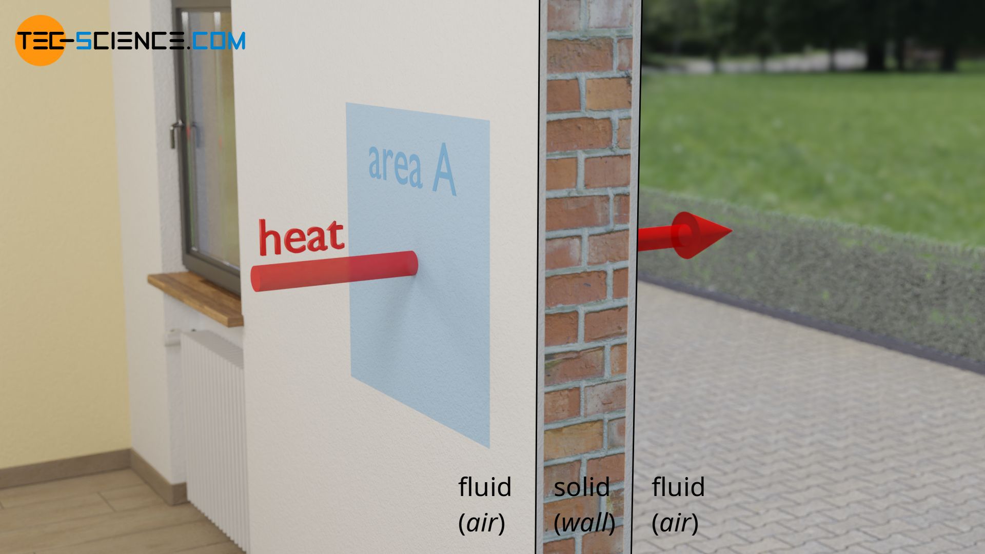
The thermal transmittance (U-value or U-factor) describes the heat transfer through a solid object, which is located between two fluids (gas or liquid) with different temperatures.
Definition and unit of the U-value
The U-value U indicates how much heat energy per unit time and unit area is transmitted through a solid object at a temperature difference of the fluids of 1 Kelvin (1 °C). The U-Value is therefore also called thermal transmittance.The U-value is therefore given in the unit “Watt per square meter and Kelvin” W/(m²⋅K). The heat transferred per unit time and unit area is also called heat flux q*.
\begin{align}
\label{def}
&\boxed{U := \frac{Q}{\Delta t \cdot A \cdot \Delta T}} \\[5px]
&U = \underbrace{\frac{Q}{\Delta t}}_{\text{rate of heat flow }\dot Q} \cdot \frac{1}{A \cdot \Delta T} \\[5px]
&U = \underbrace{\frac{\dot Q}{A}}_{\text{heat flux }\dot q} \cdot \frac{1}{\Delta T} \\[5px]
&\boxed{U := \frac{\dot q}{ \Delta T}}\\[5px]
\end{align}
The higher the U-value, the more heat flows through an object within a certain time and the lower the insulation. Low U-values therefore mean good thermal insulation properties.
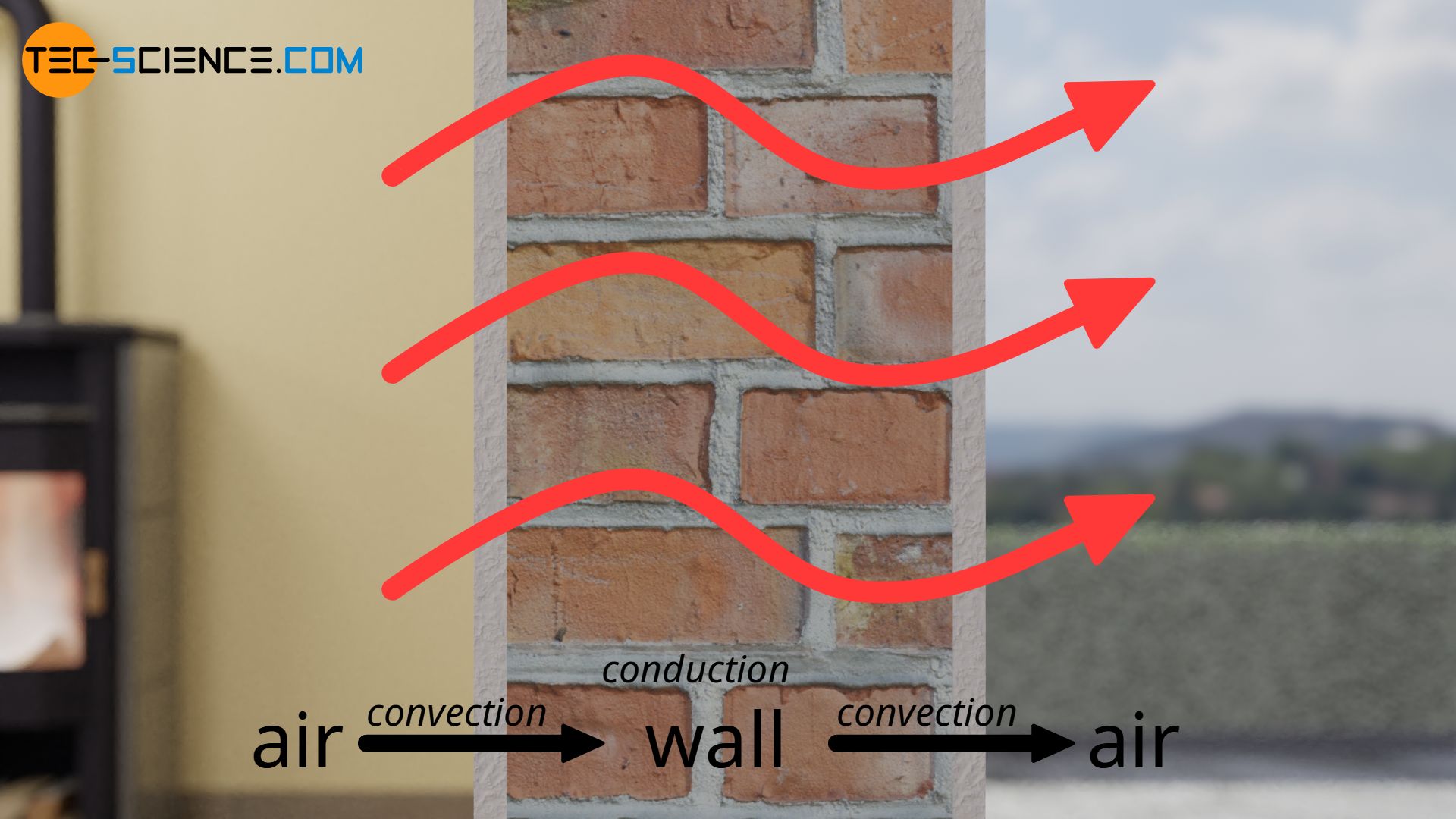
The U-value depends mainly on the thermal conductivity of the solid (heat transfer by thermal conduction), but also on the heat transfer coefficient between fluid and solid or solid and fluid (heat transfer by thermal convection). In addition, heat transfer by thermal radiation also occurs. In practice, however, the U-value for different components is usually not determined on the basis of the thermal conductivity or the heat transfer coefficient, but is determined experimentally.
According to equation (\ref{def}), for a given temperature difference ΔT in the steady state, only the amount of heat Q passing through a surface area A within the time Δt has to be determined. Special heat flow meters (HFM) are used to measure the heat flow.
Significance of the U-value
The U-value is particularly important for the envelope of buildings. In building engineering, the fluids are air. In this case, windows, masonry, plaster or other insulating materials serve as heat transmitting solids. These components should prevent the heat transfer between the interior of the house and the environment as much as possible. With regard to thermal insulation, the aim is always to use materials with the lowest possible U-values in order to achieve the greatest possible insulation effect.
Using the U-value of objects, the heat flux q* passing through a component can be determined from the present temperature difference ΔT:
\begin{align}
&\boxed{\dot q = U \cdot \Delta T} ~~~\text{heat flux (rate of heat flow per unit area)} \\[5px]
\end{align}
If the area A of the object is known, then the rate of heat flow Q* transmitted through the component can be determined:
\begin{align}
&\boxed{\dot Q = U \cdot A \cdot \Delta T} ~~~\text{rate of heat flow} \\[5px]
\end{align}
The amount of heat Q that has passed through over a time duration Δt is then finally obtained by the following formula:
\begin{align}
&\boxed{Q = U \cdot A \cdot \Delta T \cdot \Delta t} ~~~\text{heat that has penetrated the object} \\[5px]
\end{align}
Calculation of the U-value (thermal resistances)
For the calculation of the U-value it is useful to define different thermal resistances depending on the different mechanisms of heat transfer. The sum of these resistances results in the total thermal resistance, the reciprocal value of which finally corresponds to the thermal transmittance (U-value).
Thermal transmittance and thermal resistance of conduction
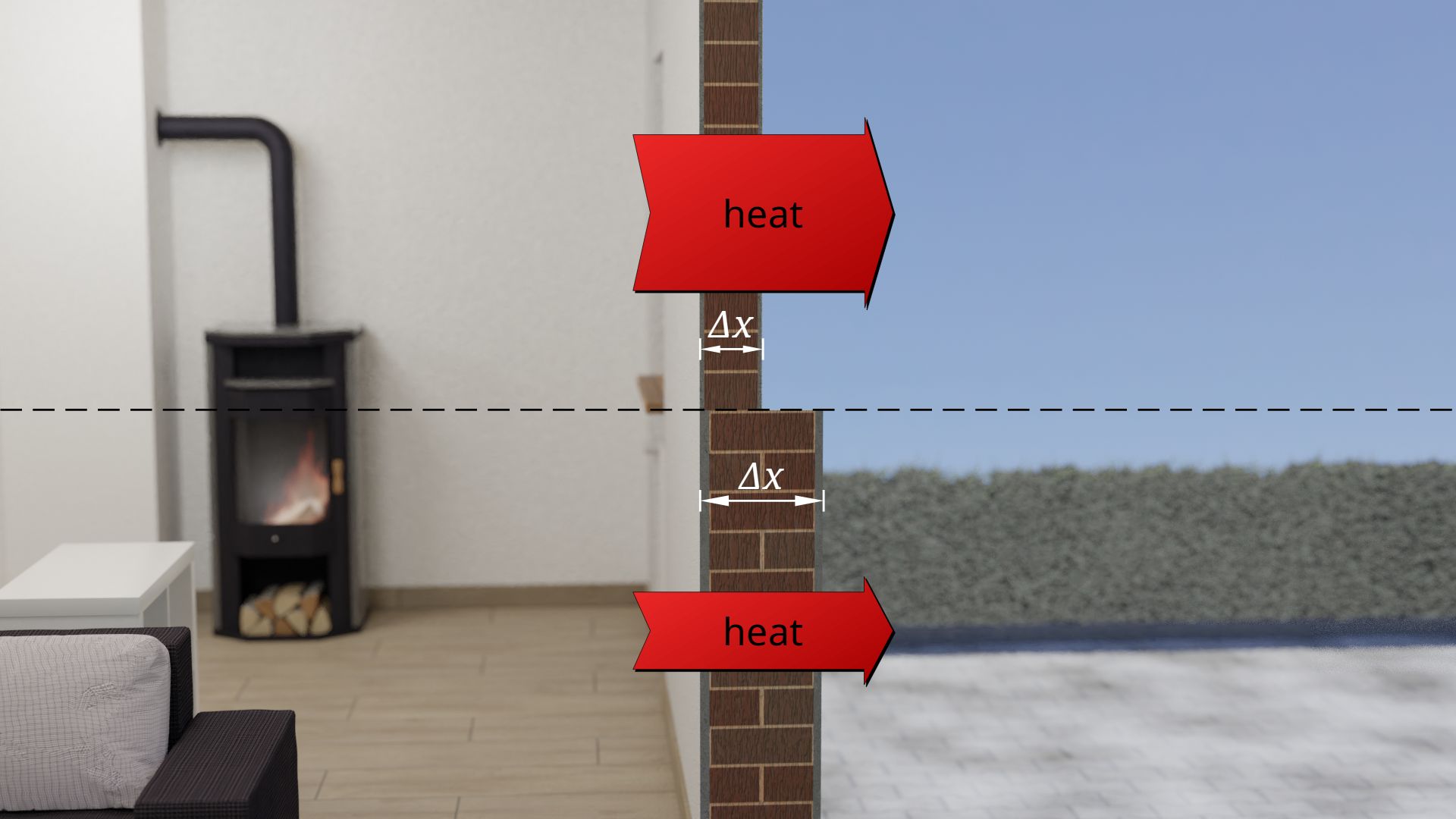
The thermal conductivity λ of a material indicates how much heat per unit time and unit area flows through the material at a given temperature difference ΔT.
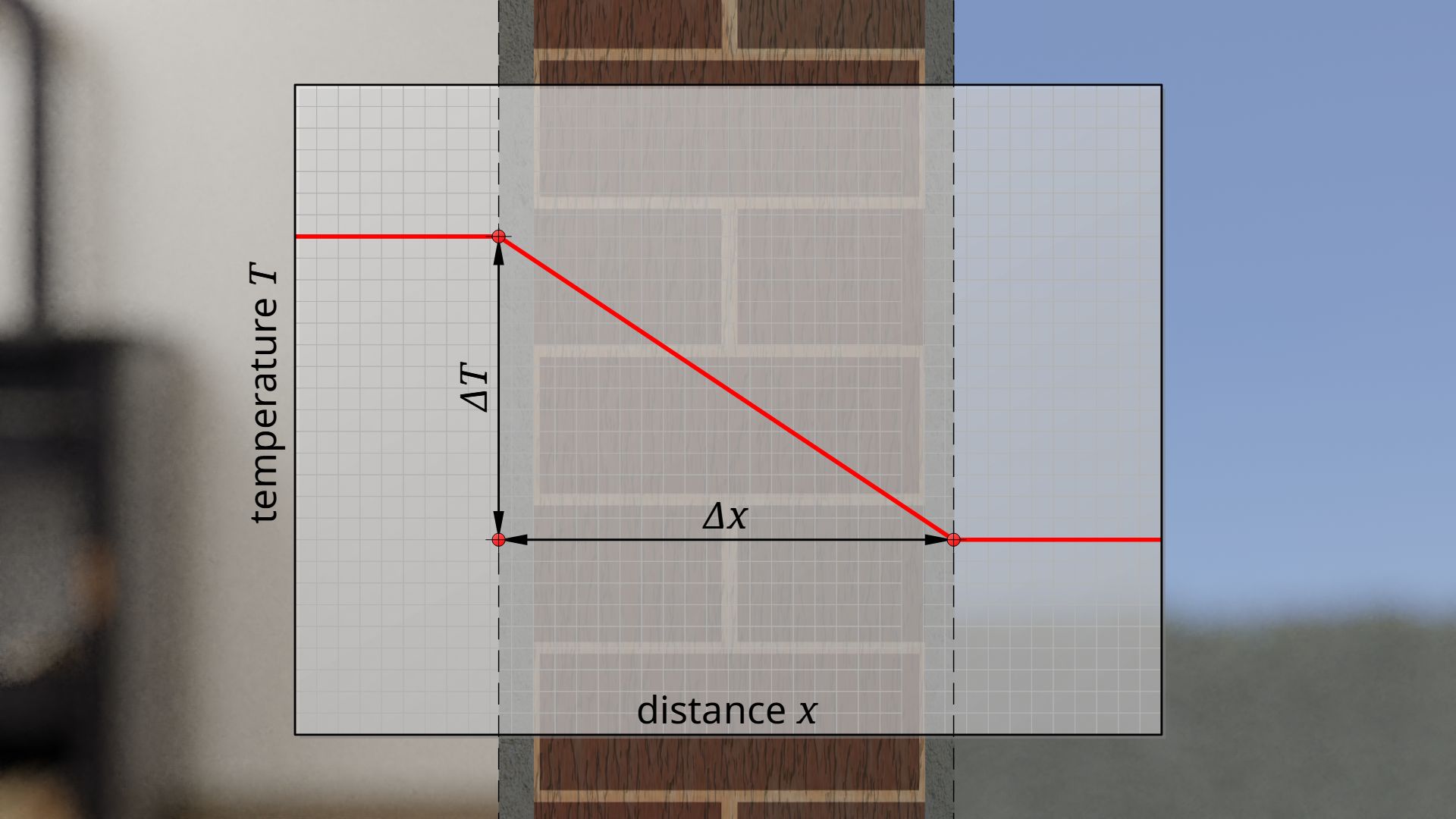
The greater the thermal conductivity of the material, the greater the heat transfer due to thermal conduction. For a given temperature difference, the resulting heat flux q*λ is significantly dependent on the thickness Δx of the material (see Fourier’s law) – for example, within a certain time less heat passes through a thick wall than through a thin wall.
\begin{align}
&\boxed{\dot q_\lambda = \lambda \cdot \frac{\Delta T}{\Delta x}}~~~~~\text{Fourier’s law} \\[5px]
&\dot q_\lambda = \underbrace{\frac{\lambda}{\Delta x}}_{\text{thermal transmittance}\\{\text{of conduction }\Lambda}} \cdot \Delta T \\[5px]
\end{align}
Since the combination of thermal conductivity and thickness of the material is a property of the component, these quantities are combined to new quantity: the thermal transmittance of conduction Λ. Note that this quantity does not describe the overall thermal transmittance (U-value) of the component but only the heat transfer due to thermal conduction):
\begin{align}
\label{ql}
&\boxed{\dot q_\lambda = \Lambda \cdot \Delta T}~~~\text{where}~~ \boxed{\Lambda=\frac{\lambda}{\Delta x}}~~\text{thermal transmittance of conduction} \\[5px]
\end{align}
The thermal transmittance of conduction is a component-dependent quantity that describes the heat transfer through a component due to thermal conduction!
The greater the thermal transmittance of conduction, the more heat is transmitted due to thermal conduction and the lower the effect of insulation. The reciprocal of the thermal transmittance is therefore called thermal resistance R:
\begin{align}
&R:=\frac{1}{\Lambda} \\[5px]
\label{a}
&\boxed{R=\frac{\Delta x}{\lambda}}~~[R]=\frac{\text{m²K}}{\text{W}} ~~~\text{thermal resistance of conduction} \\[5px]
\end{align}
The thermal resistance of conduction is a component-dependent quantity that is a measure for thermal insulation of a component with regard to thermal conduction!
Heat transfer coefficient and thermal resistance of convection
The heat transfer coefficient α describes how much heat per unit time and unit area at a given temperature difference ΔT flows through the interface between a fluid and a solid or vice versa.
Unlike thermal conduction, which describes the heat transfer inside a solid, the heat transfer coefficient describes the heat transfer by thermal convection at the interface between fluid and solid! The higher the heat transfer coefficient, the stronger the heat transfer due to convection. For the heat flux in this case applies:
\begin{align}
\label{qk}
&\boxed{\dot q_\text{s} = \alpha \cdot \Delta T} \\[5px]
\end{align}
The index s stands for surface, and expresses that this heat flux refers to the interface between fluid and solid.
The heat transfer coefficient describes as a component-dependent quantity the heat transfer at the interface between fluid and solid due to convection!
Remark: In building engineering, the heat transfer coefficient is often denoted by the letter h instead of α.
The greater the heat transfer coefficient, the more heat is transferred by convection and the lower the effect of insulation. The reciprocal of the heat transfer coefficient is therefore called thermal resistance of convection Rs (also called heat transfer resistance):
\begin{align}
\label{rk}
&\boxed{R_\text{s} =\frac{1}{\alpha}}~~[R_\text{s}]=\frac{\text{m²K}}{\text{W}} ~~~\text{thermal resistance of convection} \\[5px]
\end{align}
The thermal resistance of convection is a component-dependent quantity that is a measure for thermal insulation of a component with regard to thermal convection!
Heat transfer by thermal radiation
The mathematical description of thermal radiation could in principle be described in a similar way as that of thermal conduction or convection. In practice however, the experimental determination of the heat transfer coefficient always includes thermal radiation. The heat flux according to equation (\ref{qk}) thus results from the portion that is actually due to convection (αc) and from thermal radiation (αr):
\begin{align}
\label{qs}
&\boxed{\dot q_\text{s} = \left(\alpha_\text{c} +\alpha_\text{r} \right)\cdot \Delta T} \\[5px]
\end{align}
In this respect, thermal radiation is already taken into account by the thermal resistance of convection according to equation (\ref{rk}):
\begin{align}
&\boxed{R_\text{s} =\frac{1}{\alpha}=\frac{1}{\alpha_\text{c}+\alpha_\text{r}}} \\[5px]
\end{align}
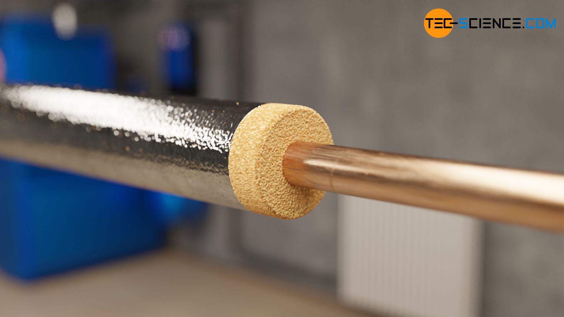
In building engineering, thermal radiation usually only plays a noticeable role when there are large temperature differences. This situation is usually not given with the envelope of a building. In this case, thermal radiation is only of minor importance. In the case of hot water pipes, however, due to the large temperature difference between water and the environment, thermal radiation can play a greater role and must then be explicitly taken into account.
In order to also take measures to limit heat loss through radiation, hot water pipes are therefore usually wrapped with reflective foil in addition to a thermal insulating layer. This minimizes radiation losses due to the reflections taking place and thus prevents heat transfer by radiation to the greatest possible extent.
Overall thermal resistance and thermal transmittance (U-value)
If heat is to flow from one fluid to another fluid, separated by a solid, the heat must first overcome the thermal resistance of convection on the internal inside of the solid, so to speak. Then the thermal resistance of conduction must be overcome to get through the solid to the other side. Finally, a further heat transfer between solid and fluid takes place, which will also be governed by convection (thermal resistance of convection).
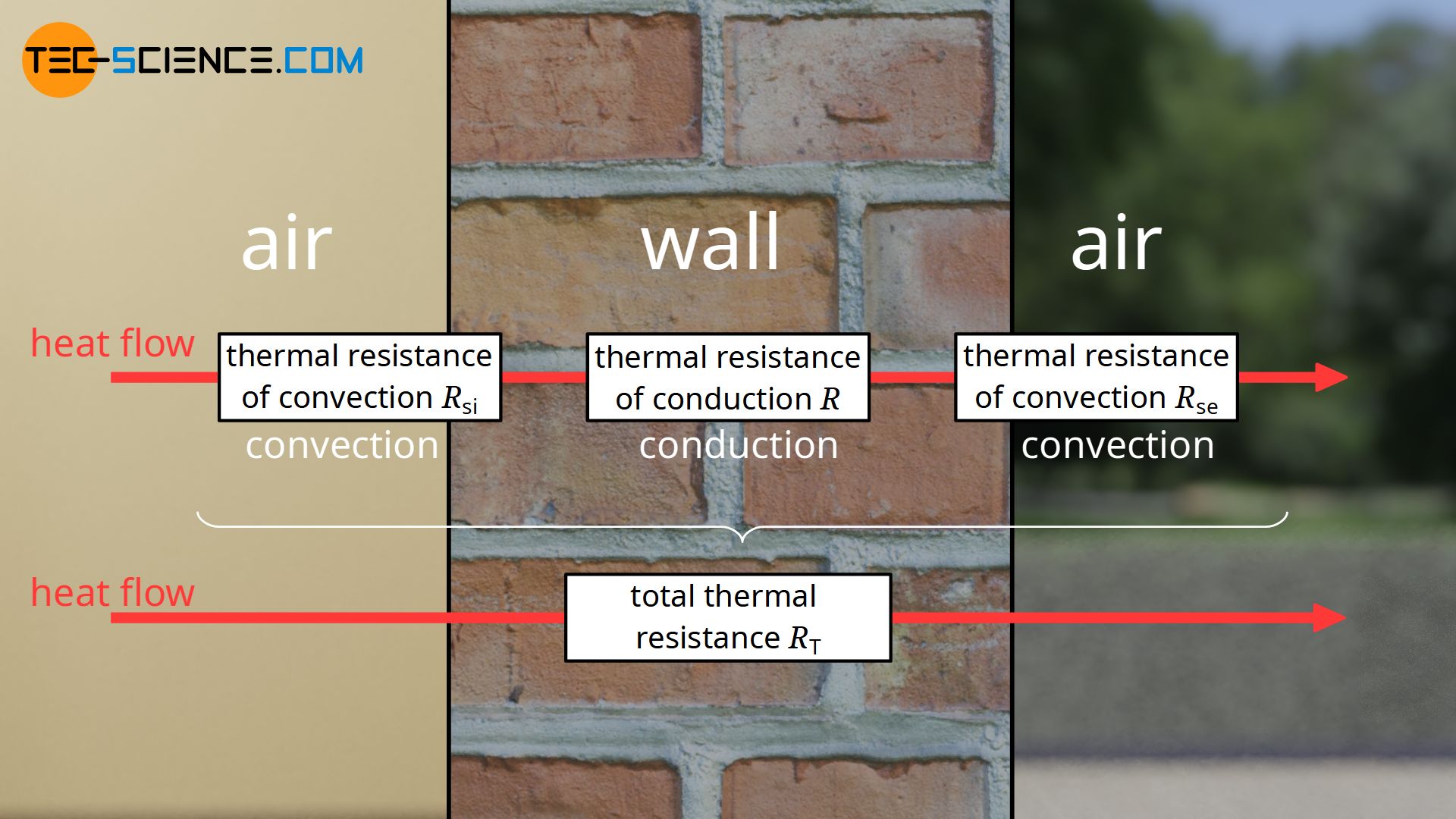
Note that the thermal resistance of convection on the inside is usually different from that on the outside. This is especially true if a component is made of different material layers and the outer and inner surfaces are therefore made of different materials, each of which has a different thermal resistance. Especially in buildings, wind speeds also play a role, which are obviously different inside the building than outside. This also means that the convective heat transfer on the inside of the wall is different from that on the outside.
The difference in thermal resistance is indicated by an additional letter. The thermal resistance Rsi denotes the thermal resistance of convection at the interior side and Rse denotes the thermal resistance at the exterior side. The terms internal and external refer to the direction of heat flow, i.e. from “warm to cold”.
The sum of the two thermal resistances of convection on the exterior and interior side (Rsi and Rse), as well as the thermal resistance of conduction R of the solid, finally results in the overall thermal resistance RT:
\begin{align}
&\boxed{R_\text{T} =R_\text{si} + R + R_\text{se}} ~~~\text{overall thermal resistance}\\[5px]
\end{align}
If the considered component is an assembly of several different material layers, the sum of the respective thermal resistances is to be taken as a basis (note that there is no thermal convection between the individual layers):
\begin{align}
&\boxed{R_\text{T} =R_\text{si} + \sum R + R_\text{se}} ~~~\text{overall thermal resistance} \\[5px]
\end{align}
The individual resistances to the heat flow can be considered analogous to electrical resistances in electrical engineering. If resistors are connected in series, the individual resistances can be added to the total resistance.
The reciprocal value of the overall thermal resistance finally corresponds to the overall thermal transmittance (U-value):
\begin{align}
&\boxed{U = \frac{1}{R_\text{T}} =\frac{1}{R_\text{si} + \sum R + R_\text{se}}} ~~~\text{U-value}\\[5px]
\end{align}
Example of U-value calculation in the envelope of a building
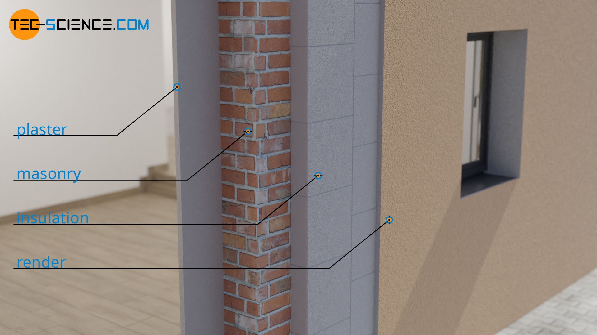
In the following, the U-value of a building wall will be calculated. From inside to outside, the wall is constructed as follows:
- plaster (2 cm)
- Masonry made of brick (30 cm)
- Thermal insulation layer (16 cm)
- render (2 cm)
Strictly speaking, the heat transfer between air and interior plaster or exterior render and air does not only depend on the temperature. Also the air velocity (wind speed outside the building) influences the heat transfer. Since differences in air density lead to free convection, the direction of the heat flow also influences the heat transfer. Therefore, a distinction must be made between horizontal, upward and downward heat flow.
For a simplified calculation, the following values for the thermal resistances of convection depending on the direction of heat flow are given according to DIN EN 6946:
| thermal resistance of convection m²⋅K/W | horizontal | upward | downward |
|---|---|---|---|
| Rsi | 0.13 | 0.10 | 0.17 |
| Rse | 0.04 | 0.04 | 0.04 |
The values of thermal conductivity of the specified material layers can be found in table books. With the respective layer thickness the thermal resistances of conduction can be determined according to equation (\ref{a}):
| material | thermal conductivity λ (m²⋅K/W) | layer thickness Δx (m) | thermal resistance R (m²⋅K/W) |
|---|---|---|---|
| plaster | 0.40 | 0.02 | 0.05 |
| masonry | 0.50 | 0.30 | 0.60 |
| thermal insulation layer | 0.032 | 0.16 | 5.00 |
| render | 0.25 | 0.02 | 0.08 |
The sum of the individual thermal resistances gives the total thermal resistance RT
\begin{align}
R_\text{T}
&= R_\text{si} + \sum R + R_\text{se}\\[5px]
&= R_\text{si} + R_\text{plaster} + R_\text{masonry} + R_\text{insulation} + R_\text{render} +R_\text{se}\\[5px]
&= \left(0.13+ 0.05 + 0.60 + 5.00+ 0.08 + 0.04 \right) \tfrac{\text{m²}\cdot \text{K}}{\text{W}} \\[5px]
&= \underline{5.90 \tfrac{\text{m²}\cdot \text{K}}{\text{W}}}\\[5px]
\end{align}
The reciprocal value of the total thermal resistance finally gives the U-value of our building wall:
\begin{align}
&U = \frac{1}{R_\text{T}} =\frac{1}{5.90 \tfrac{\text{m²}\cdot \text{K}}{\text{W}}} = \underline {0.17 \tfrac{\text{W}}{\text{m²}\cdot \text{K}}} \\[5px]
\end{align}
The U-value of the wall is 0.17 (mostly designated without units) and is thus below the value of 0.24 as prescribed by the German Energy Saving Ordinance (EnEV). In this case the U-value is significantly influenced by the thermal insulation layer, without which the U-value would be 1.11. Without thermal insulation, the heat loss through the building wall would therefore be about 6.5 times as high.
")


")

