The heat transfer coefficient describes the convective heat transfer from a solid to a flowing fluid and vice versa!
Introduction
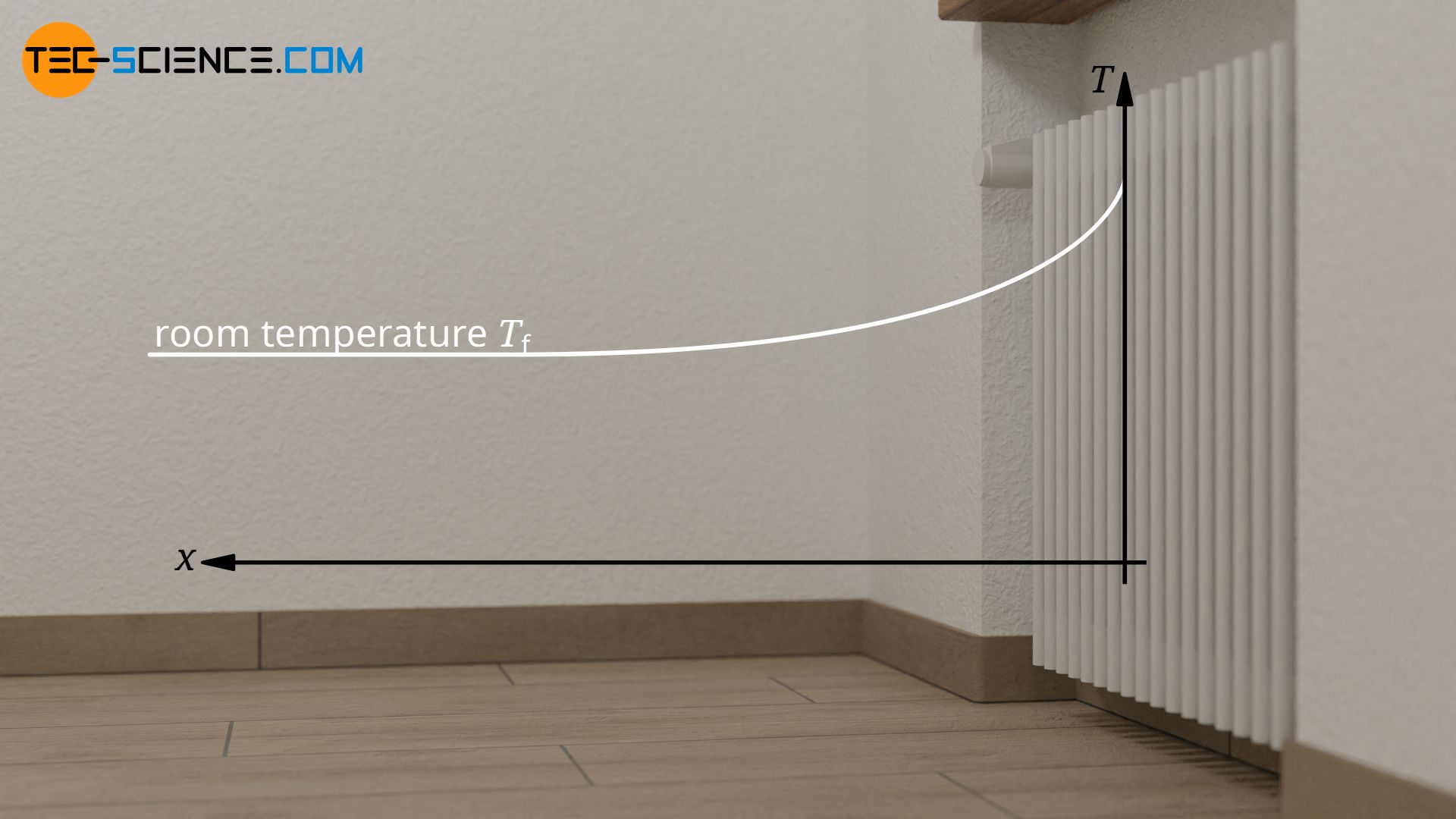
The heat transfer coefficient describes the convective heat transfer from a solid to a flowing fluid (gas or liquid) or vice versa. Such a situation can be seen, for example, with a radiator. Cold air flows past the radiator due free convection and is heated. Obviously, the radiator transfers heat to the passing air.

Such a convective heat transfer from the heated cooling fins to an air flow generated by a fan is also evident in the cooling of graphics cards. In the case of water cooling, the heat would no longer be transferred to flowing gas, but to flowing liquid. In both cases, however, it is no longer free convection but forced convection by a fan or pump.

Definition of the heat transfer coefficient
As always in thermodynamic processes, the temperature difference between solid and fluid is the driving force for the heat flow. The rate of heat flow Q* transferred from the solid to the fluid is the greater, the greater the temperature difference between the solid “wall” Tw and the flowing fluid Tf. The heat flow is proportional to the temperature difference:
\begin{align}
&\dot Q \sim (T_w-T_f) \\[5px]
\end{align}
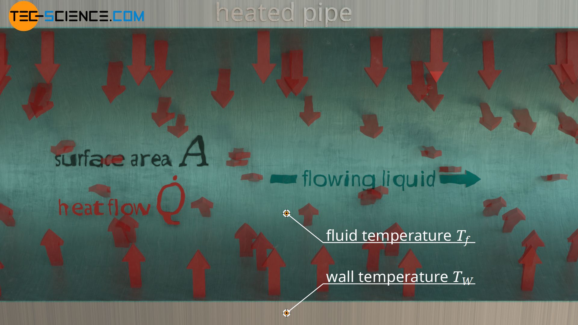
Furthermore, the heat flow depends on the surface area of the solid in contact with the passing fluid. This surface area can cover the entire inner surface of the pipe, if, for example, the entire pipe is heated, or only a part of the pipe, if the pipe is only heated selectively. The larger the area, the more heat can be transferred and the greater the heat flow through this area. For this reason, chip heat sinks consist of many cooling fins to create the largest possible surface area. Radiators also use this principle by using many individual heating pipes. There is also a proportional relationship between area A and heat flow Q*:
\begin{align}
&\dot Q \sim A \\[5px]
\end{align}
The heat flow is therefore proportional to the temperature difference and the surface area, so that by introducing a proportionality constant α the heat flow between solid and fluid can be determined as follows:
\begin{align}
&\dot Q \sim A \cdot (T_w-T_f) \\[5px]
\label{q}
&\boxed{\dot Q = \alpha \cdot A \cdot (T_w-T_f)} \\[5px]
\label{qq}
&\boxed{\dot q = \alpha \cdot (T_w-T_f)} ~~~\boxed{\dot q = \frac{\dot Q}{A}} ~~~\text{heat flux} \\[5px]
\end{align}
In equation (\ref{qq}) was used that the quotient of heat flow and area corresponds to the so-called heat flux (heat flow density). The heat flux describes the rate of heat flow per unit area (area of the wall that is in contact with the fluid). In this context the proportionality constant α can thus be defined as the relationship between heat flux and temperature difference and is called heat transfer coefficient:
\begin{align}
\label{a}
&\boxed{\alpha := \frac{\dot q}{T_w-T_f}} ~~~\text{heat transfer coefficient}\\[5px]
\end{align}
The heat transfer coefficient describes the convective heat transfer from a solid to a flowing fluid and vice versa!
Important: The heat transfer coefficient must not be confused with the thermal conductivity. The thermal conductivity describes heat transfer due to thermal conduction inside one material, while the heat transfer coefficient describes the heat transfer between two different materials due to thermal convection.
Factors influencing the heat transfer coefficient
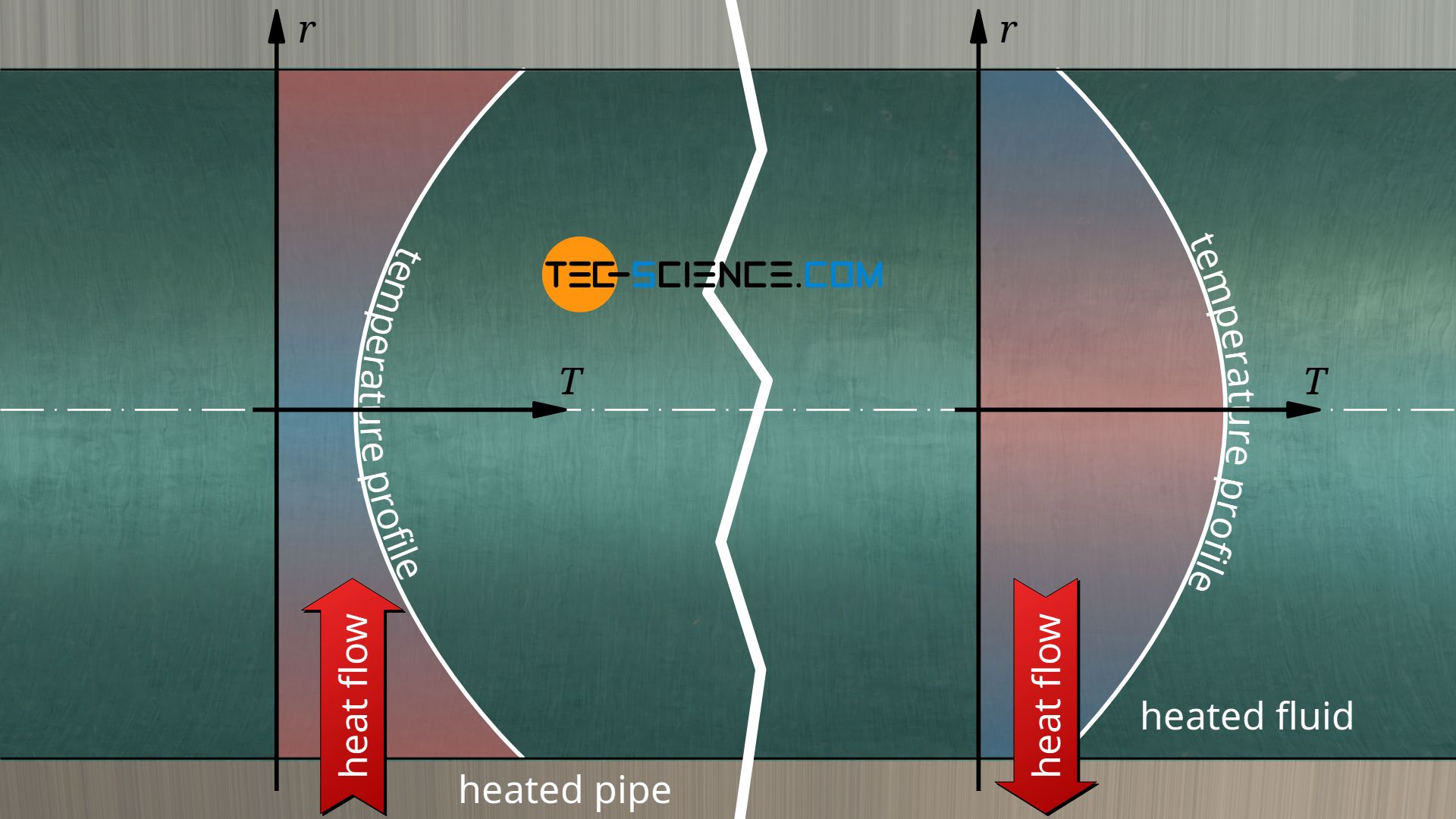
The equations (\ref{q}) and (\ref{qq}) are basically also valid for the opposite case, e.g. when heat is transferred from a flowing fluid to a solid. Such a situation can be found, for example, inside a radiator when the flowing water transfers heat to the radiator. However, the temperature distribution in the fluid is different. This in turn influences the heat transfer coefficient, despite possible identical temperature differences. The heat transfer coefficient is therefore also dependent on the direction of heat flow.
In contrast to the thermal conductivity, the heat transfer coefficient is not a material constant. The heat transfer coefficient depends, among other things, on the material combination solid/fluid. The roughness of the surface of the solid also plays a role. In addition, the flow velocity influences the heat transfer and especially the type of flow, i.e. whether the flow is laminar or turbulent.
The heat transfer coefficient is influenced, among other things, by the combination of the substances, surface properties, flow velocity and type of flow and direction of the heat flow!
Furthermore, the heat transfer coefficient depends on the size of the system. In the case of a pipe, it depends on the diameter and in the case of a plate on the size of the plate. For similar flow conditions, lower heat transfer coefficients are obtained for larger systems. The heat transfer coefficient is therefore always dependent on a specific application. Without further ado a general description of convection processes is therefore not possible. Such a general description is only possible by introducing a dimensionless similarity parameter, the so-called Nusselt number. More information on this can be found in the linked article.
Reference temperatures
If, as in the case of the radiator, the temperature of the air flowing past is mentioned, the question arises as to what exactly this temperature refers to. The air temperature is obviously higher near the radiator than at a greater distance. In most cases the heat transfer coefficient therefore refers to the fluid temperature at a sufficiently large distance from the wall, where the temperature perpendicular to the main flow direction* hardly changes (also called freestream temperature). For such external flows the symbol T∞ is therefore often used instead of Tf. In the case of the radiator, this reference temperature would be to the room temperature in the middle of the room.
Also with a fluid inside a pipe, for example when hot water flows through the pipe system of the radiator, different temperatures exist in the fluid. In the center of the pipe (core flow), the water is hotter than near the pipe wall, where the fluid has already transferred heat to the pipe wall. However, unlike the surrounding air outside the radiator, the water inside the radiator is only in a very localized area. For this reason, the fluid temperature of an internal flow refers to the mean temperature inside the pipe. This average temperature would correspond to the mixing temperature if the fluid were ideally mixed.
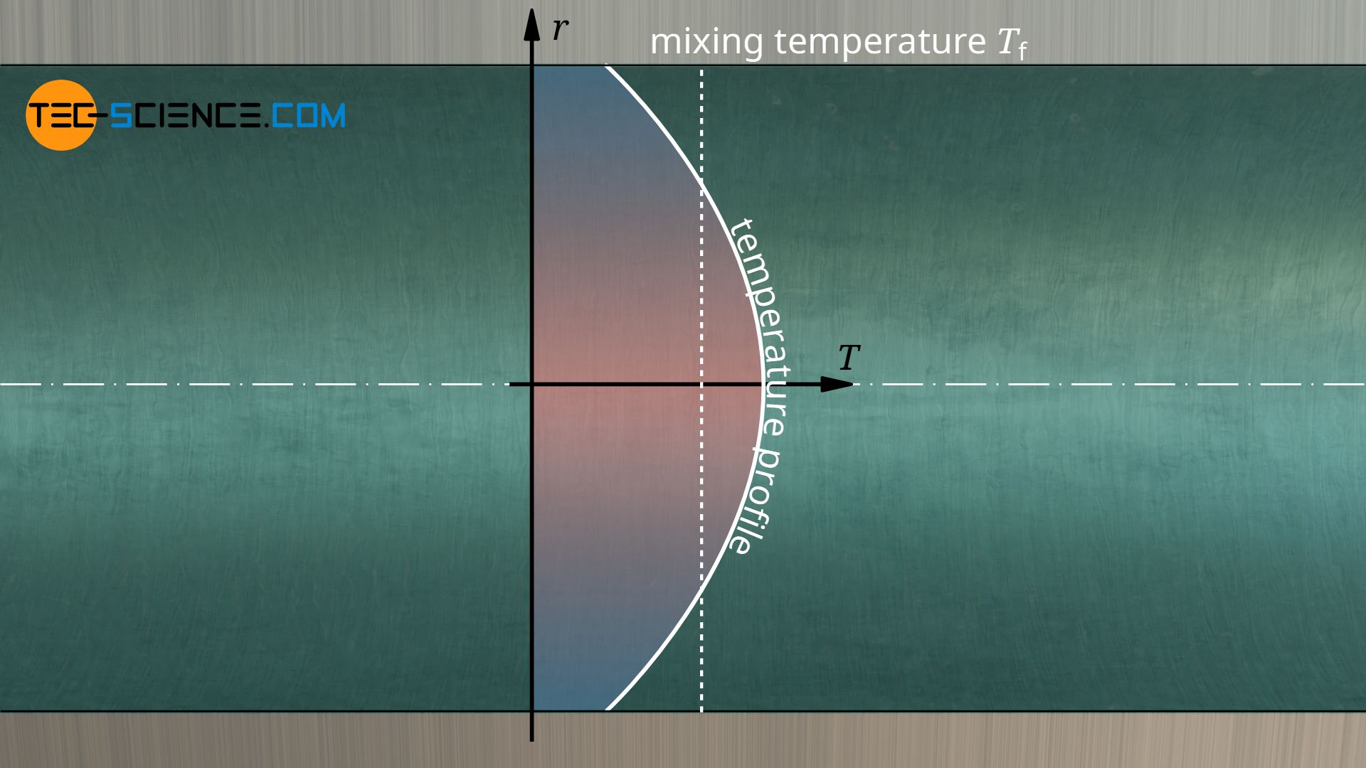
For external flows, the fluid temperature refers to the temperature at a sufficiently large distance from the wall and for internal flows to the mean temperature of the fluid!
*) Note: In addition to the main flow direction of the fluid, which in pipes is usually forced by a pump (forced convection), free convection also exists due to density differences resulting from temperature differences. In practice, therefore, both flows overlap. Depending on the situation, free convection can make a considerable contribution to the total heat transfer.
Importance of the boundary layer for heat transfer
If a fluid flows along a wall, this has an effect on the flow velocity. Due to the frictional forces (described by the viscosity) between wall and fluid and within the fluid, the flow velocity of the fluid is disturbed. This disturbed layer of velocity is also called the velocity boundary layer (also called hydrodynamic boundary layer). Due to the no-slip condition, the velocity of the fluid directly at the wall is zero and then slowly increases.
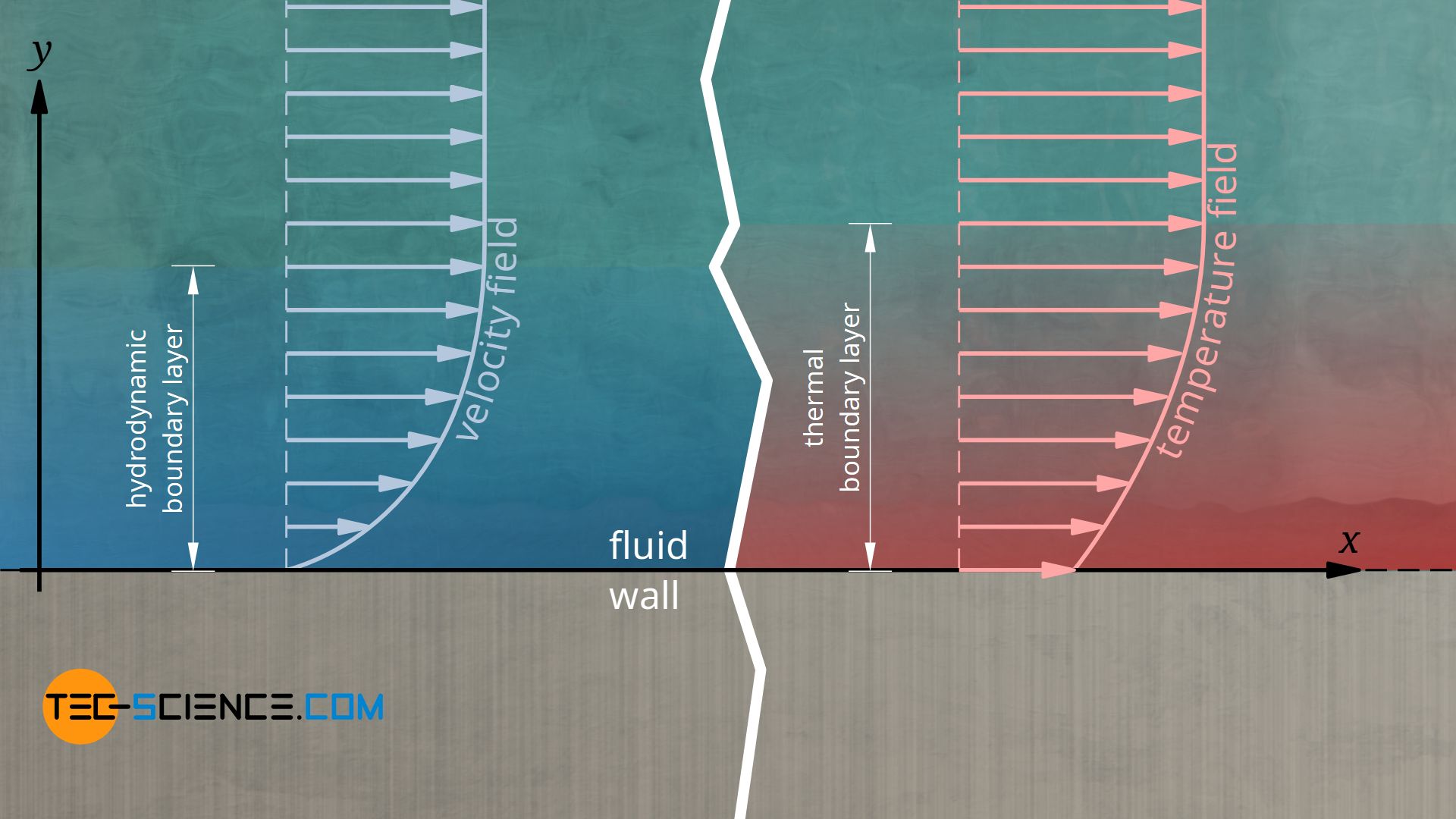
Since the fluid thus adheres directly to the wall and is therefore not subject to convection, heat transport there is only possible by thermal conduction. Note that this does not mean that convection does not have a significant effect on the overall heat transfer! Because due to the convective processes the whole temperature field changes compared to a situation without convection (the ratio of heat transport in the presence of convection compared to a situation without convection is described by the so-called Nusselt number)! Nevertheless, the Fourier’s law of thermal conduction applies directly on the wall λf denotes the thermal conductivity of the fluid):
\begin{align}
& \dot{q_w} =- \lambda_f \cdot \left(\frac{\text{d}T_f}{\text{d}y}\right)_\text{wall} \\[5px]
\end{align}
Using equation (\ref{a}), the heat transfer coefficient is given by the following formula:
\begin{align}
&\alpha = \frac{\dot q_w}{T_w-T_f}\\[5px]
\label{wand}
&\boxed{\alpha = \frac{- \lambda_f \cdot \left(\frac{\text{d}T_f}{\text{d}y}\right)_\text{wall}}{T_w-T_f}}\\[5px]
\end{align}
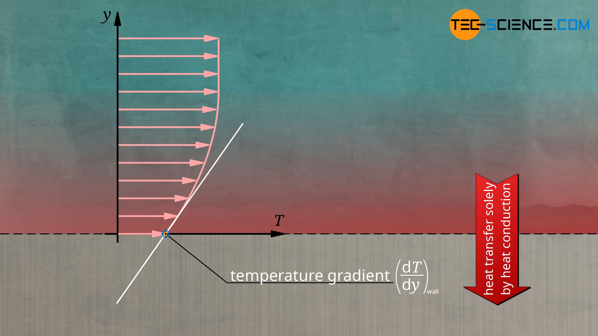
As can be seen from this equation, the temperature gradient on the wall therefore has a decisive influence on the heat transfer coefficient. However, the distribution of the temperature in the fluid (temperature field) depends on the flow conditions in the fluid (velocity field). Conversely, the temperature field in turn influences the viscosity of the fluid and thus the velocity field. Velocity field and temperature field therefore influence each other.
The boundary layer between fluid and wall has a decisive influence on the overall convective heat transfer!
Local and average heat transfer coefficient
The boundary layer explained in the previous section is generally not a uniform area, so that different flow conditions arise depending on the location. Thus this also influences the temperature field, especially the temperature gradients at the wall. According to the above equation (\ref{wand}), this leads to different heat transfer coefficients depending on the location. In this context one also speaks of a local heat transfer coefficient.
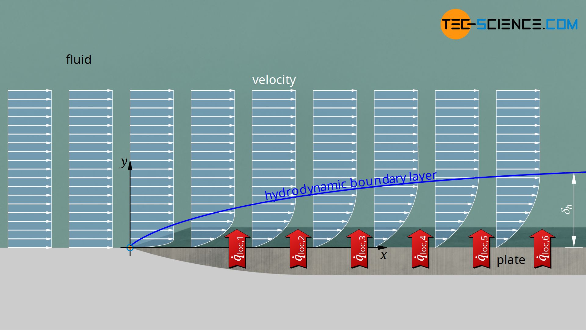
To better illustrate this situation, let us consider an isothermally heated plate, which is flowed over by a fluid. The planar flow is assumed to be laminar. When the fluid flows over the plate, the fluid layer directly on the wall adheres to it (no-slip condition). This causes the fluid layers above to be slowed down as the flow continues. The region where the velocity is disturbed thus gradually grows until at some point a constant boundary layer thickness δh has formed.
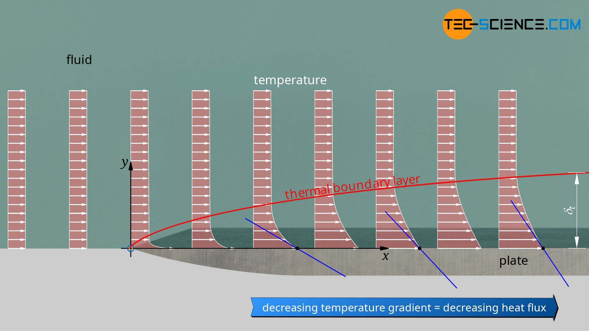
In the same way, a thermal boundary layer forms when the fluid flows over the plate. While the temperature within the undisturbed flow is constant at every point, the fluid is heated when it flows over the plate. In the further course the heat penetrates deeper into the fluid. Thus, not only is there an area above the plate in which the velocity is disturbed, but also an area in which the temperature is disturbed. Both boundary layers generally differ from each other (how exactly these boundary layers are defined is explained in the article Boundary layer and dimensionless similarity parameters)!
It is now clear that the interacting velocity field and temperature field varies from place to place. The heat transfer therefore also differs from place to place. Consequently, at each position x a local heat transfer coefficient αloc can be defined, which describes the local heat flux q*loc:
\begin{align}
&\boxed{\dot q_\text{loc} = \alpha_\text{loc} \cdot (T_w-T_f)} ~~~~~\text{local heat flux} \\[5px]
\end{align}
Note that the temperature Tw refers to the constant wall temperature and Tf to the temperature of the undisturbed flow (freestream). The term Tw-Tf is therefore constant regardless of the position x. The local heat flux is therefore only influenced by the local heat transfer coefficient!
Computer simulations make it relatively easy to determine the local heat transfer coefficients, so that after integrating the local heat fluxes with respect to the surface area of the plate, the overall convective heat flow Q* can be determined:
\begin{align}
\label{dqq}
& \dot Q = \int \limits_A \dot q_\text{loc} ~ \text{d}A= (T_w-T_f) \int \limits_A \alpha_\text{loc} ~ \text{d}A \\[5px]
\end{align}
With the definition of an average heat transfer coefficient,
\begin{align}
\label{ma}
& \boxed{\overline{\alpha} =\frac{1}{A} \int \limits_A \alpha_\text{loc} ~ \text{d}A} ~~~~~\text{average heat transfer coefficient} \\[5px]
\end{align}
the overall heat transfer from to plate to the liquid can be determined as follows:
\begin{align}
\label{dq}
& \boxed{\dot Q = \overline{\alpha} \cdot A \cdot (T_w-T_f)} ~~~~~\text{total convective heat transfer} \\[5px]
\end{align}
Note that when equation (\ref{ma}) is inserted into equation (\ref{dq}), equation (\ref{dqq}) results.
In this context, equation (\ref{wand}) is to be considered more closely, which shows the (local) heat transfer coefficient as a function of the temperature gradient at a point x on the wall:
\begin{align}
&\boxed{\alpha_\text{loc} = \frac{- \lambda_f \cdot \left(\frac{\text{d}T_f}{\text{d}y}\right)_\text{wall,x}}{T_w-T_f}}\\[5px]
\end{align}
If a constant thermal conductivity λf of the fluid is assumed, the only parameter that changes in this equation is the temperature gradient. As the position x increases, the thickness of the thermal boundary layer increases, i.e. the temperature increases over a greater distance y. Thus, the temperature gradient decreases in the x-direction and so does the local heat transfer coefficient. The local heat flux thus also decreases along the plate (see figure above)!
This is also clear, because if you imagine an (infinitely) long plate, then at some point the fluid will have heated up so much that it will have (almost) the same temperature as the wall of the pipe. In this case there is no temperature gradient between wall and fluid and thus no drive for a heat flow. The heat flow must therefore inevitably decrease when the fluid flows over the isothermally heated plate, as the temperatures equalise more and more.
")
")


")
