With the Guarded-Hot-Plate method (GHP) the thermal conductivity is determined by the electrical power output of a hot plate with guided heat conduction.
Thermal conductivity
Thermal conductivity is a measure of how well or poorly a material conducts heat. The rate of heat flow Q* through a material can be determined by the following equation. In this equation, Δx denotes the thickness of the material along which the heat flows and A is the area through which the heat passes. The temperature drop ΔT corresponds to the temperature difference along the thickness Δx of the material. For these given parameters, the heat flow ultimately depends on the property of the material and is described by its thermal conductivity λ.
\begin{align}
&\boxed{\dot Q= \lambda \cdot A \cdot \frac{ \Delta T }{ \Delta x }} ~~~\text{rate of heat flow} \\[5px]
\end{align}
This means, that the thermal conductivity λ of a material can be determined by generating a heat flow Q* through a slab-shaped sample of thickness Δx and area A and measuring the temperature difference ΔT:
\begin{align}
\label{a}
&\boxed{\lambda =\frac{\dot Q \cdot \Delta x}{\Delta T \cdot A}} ~~~\text{thermal conductivity} \\[5px]
\end{align}
In the article Experimental setup for determining the thermal conductivity, an experiment based on this idea has already been explained. However, there was a temperature difference and the heat flow rate was determined by melting of an ice block. With the Guarded-Hot-Plate method, which will be presented in the following, the heat flow is generated by an electric heater and the resulting temperature difference is measured.
Design of a Guarded-Hot-Plate apparatus
With the guarded hot plate method, a material sample is heated from one side by an electrically heated plate. The heat output (= rate of heat flow) corresponds to the electrical power supplied to the heating. The heating plate is embedded in a recess of a metal plate (called guard), which is separately tempered to the same temperature as the heating plate. In most cases the temperature of the guard is controlled with hot water circulation system. The bottom side of the sample is also often temperature controlled with water, but with a lower temperature.
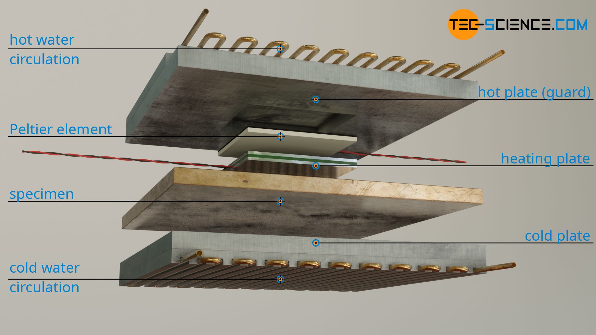
The generation of the heat flow by a heated hot plate and the surrounding guard gives this method the name Guarded-Hot-Plate method (GHP).
With such an apparatus, an easily measurable temperature difference ΔT is obtained over the sample thickness Δx. Using the supplied electrical power Q* (= heat output) the thermal conductivity λ of the specimen can finally be determined. The area A to be taken as a basis for the calculation corresponds to the area of the heating plate, since the heat emitted ideally penetrates the sample along a straight path and therefore refers to this area. In order to come as close as possible to this ideal case where heat only flows in one direction and not to let any heat flow off to the side, the guard is there. This will be discussed in more detail in the next section.
Guard
The heating plate completely converts electrical energy into heat energy. However, the electrical power only corresponds completely to the heat flow through the sample if it is ensured that all the heat produced actually passes through the sample in a straight line. Therefore, the heat must not be allowed to flow off sideways or backwards, because then only a lower heat output would pass through the sample.
This is exactly where the guard comes into play, whose basic idea has already been explained in detail in the article Experimental setup for determining the thermal conductivity. Such a guard is only a solid metal body with a recess into which the heating plate is inserted. As far as heating is concerned, the heating plate and the guard are two completely separate systems, even if both are heated to the same temperature. While the heating plate is heated electrically, the guard is usually temperature controlled with a water circulation system (even if theoretically a second electric heater could be used).
The identical temperature of the guard now ensures that the heat produced by the heating plate is only transferred downwards and thus completely through the sample. A heat flow from the heating plate to the surrounding guard is prevented exactly by the fact that both have the same temperature. Note that if there is no temperature difference, there is no heat flow, because the formation of a heat flow requires a temperature difference or a temperature gradient.
The figure below shows the simulation of the temperature distribution and thus the heat flow (green arrows). It can be seen that the guard not only ensures that the heat output of the heating plate is emitted completely downwards, but also on an almost straight path. This is called a one-dimensional heat flow. In fact, equation (\ref{a}) is only valid if such a one-dimensional heat flow exists.
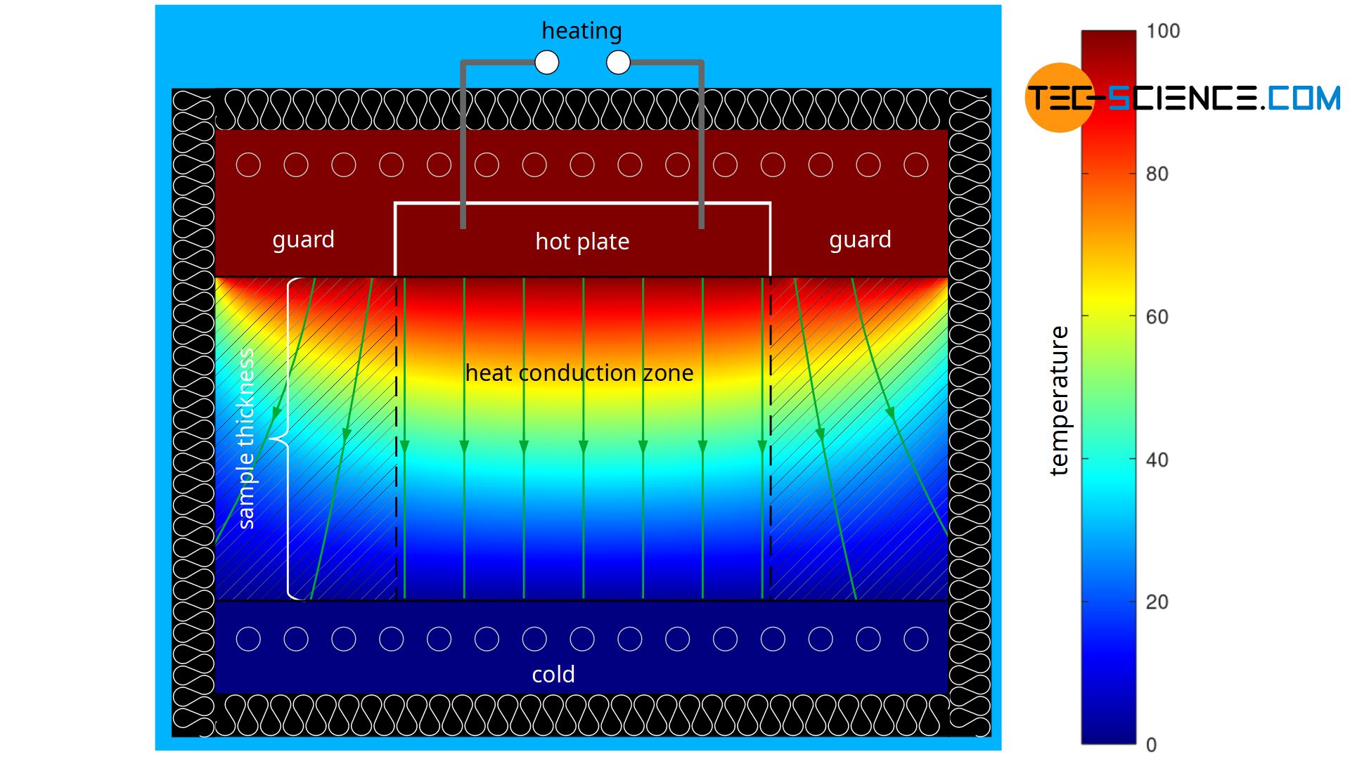
Note that the lateral, two-dimensional heat flows in the area below the guard are not due to the power of the heating plate, but to the heat output of the guard. However, both systems are completely separate from each other. The one-dimensional heat flows in the area of the actual measuring zone (heat conduction zone) are therefore solely due to the power of the heating plate.
The two-dimensional heat flows can be further minimized by placing the apparatus in a closed housing to reduce convection flow at the edges of the sample. In addition, the inside of the housing can also be temperature controlled by heating rings to further optimize the required one-dimensional heat flow. This is particularly relevant for thermal conductivity measurements with increased or decreased temperatures.
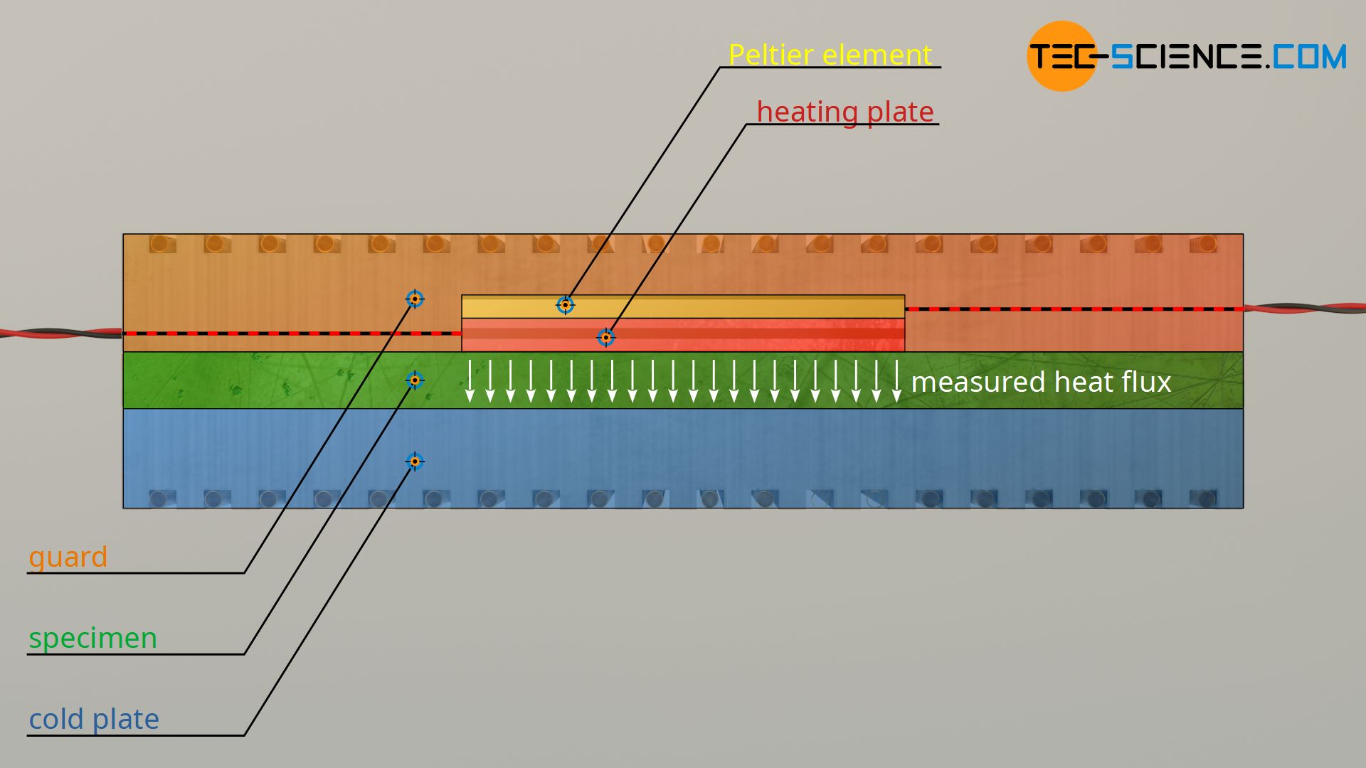
Summary: The heat output within the heat conduction zone on which the determination of the thermal conductivity is based is only determined by the electrical output of the heating plate! Although the temperature control of the guard also requires a separate heat output, this only ensures a one-dimensional heat flow within the heat conduction zone (measuring zone).
Monitoring the temperature of the heating plate and guard
With the help of a guard, a backward or lateral heat flow of the heating plate can be prevented. However, this requires that the guard and the heating plate have identical temperatures so that no heat flow can occur. Whether this is actually the case is determined in practice with a so-called Peltier element. Such an element is located on the back between the heating plate and the guard. According to the Seebeck effect (thermoelectric effect), such an element generates a voltage as soon as there is a temperature difference and thus a heat flow. In this way it is relatively easy to check whether the heating plate and guard are at the same temperature: Not voltage, no heat flow.
Field of application, advantages and disadvantages
The accuracy in the determination of the thermal conductivity using the Guarded-Hot-Plate method depends, among other things, on the temperature. Uncertainties of measurement at room temperature are in the order of approx. 2 %. At significantly lower temperatures (e.g. -150 °C) or at significantly higher temperatures (e.g. 600 °C) the measurement uncertainty due to heat loss to the environment is somewhat greater and is in the order of about 5 %.
Since the Guarded-Hot-Plate method is used to measure thermal conductivity directly on the basis of the measured values, it is also referred to as an absolute measurement method. In contrast, the Heat-Flow-Meter method is a so-called relative measurement method (comparative measurement method). The GHP method is used to measure thermal conductivity values in the range between 0.001 W/(mK) and a maximum of 5 W/(mk) at temperatures between around -150 °C and +600 °C.
")


")

