With the Heat-Flow-Meter method (HFM) the thermal conductivity is determined by comparative measurement of the heat flow using a reference sample.
Thermal conductivity
Thermal conductivity is a measure of how well or poorly a material conducts heat. The rate of heat flow (\dot Q) through a material can be determined by the following equation. In this equation, Δx denotes the thickness of the material along which the heat flows and A refers to the area through which the heat passes. The temperature drop ΔT corresponds to the temperature difference along the distance Δx. Given these parameters, the rate of heat flow ultimately depends on the property of the material and is described by its thermal conductivity λ.
\begin{align}
\label{a}
&\boxed{\dot Q= \lambda \cdot A \cdot \frac{ \Delta T }{ \Delta x }} ~~~\text{rate of heat flow} \\[5px]
\end{align}
This means that the thermal conductivity λ of a material can be determined by generating a temperature difference on a slab-shaped sample of thickness Δx and area A and measuring the heat flow rate Q* passing through:
\begin{align}
\label{b}
&\boxed{\lambda =\frac{\dot Q \cdot \Delta x}{\Delta T \cdot A}} ~~~\text{thermal conductivity} \\[5px]
\end{align}
In the article Experimental setup for determining thermal conductivity, an experiment based on this idea has already been explained. However, there was a temperature difference and the heat flow rate was determined by melting of an ice block. With the Heat-Flow-Meter method (HFM) described in the following, the heat flow is not measured by means of a melting process, but by means of a calibrated heat flow meter.
Design of a Heat-Flow-Meter apparatus
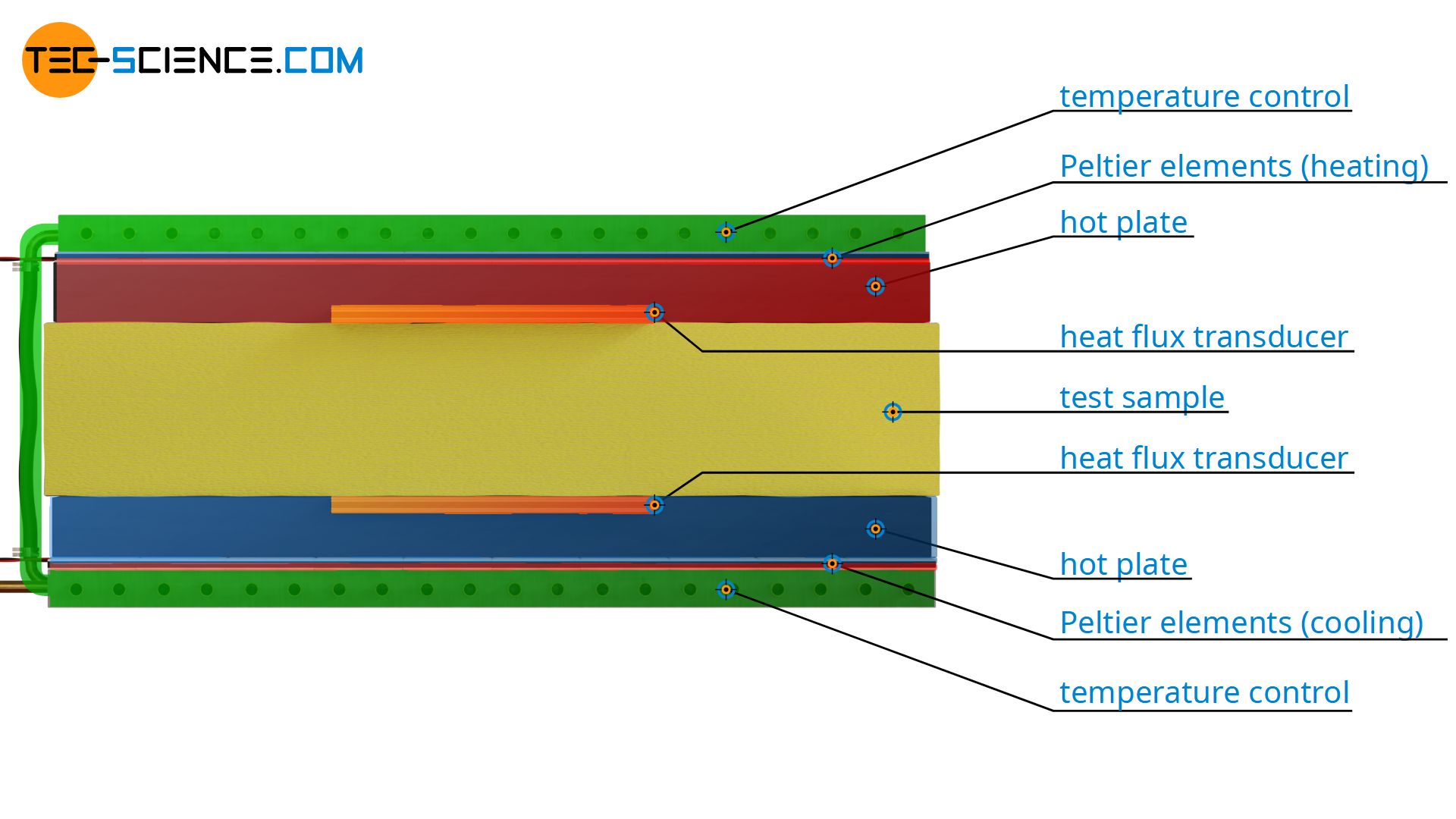
With the Heat-Flow-Meter method, a material sample of known thickness Δx is placed between a heated and a cooled plate. The temperature difference ΔT is thus fixed. The rate of heat flow Q* through the test sample is determined by means of a heat flow meter. This plate-shaped measuring device is located between the sample and the temperature-controlled heating plate or cooling plate. The area A required to calculate the thermal conductivity corresponds to the area of the heat flow meter.
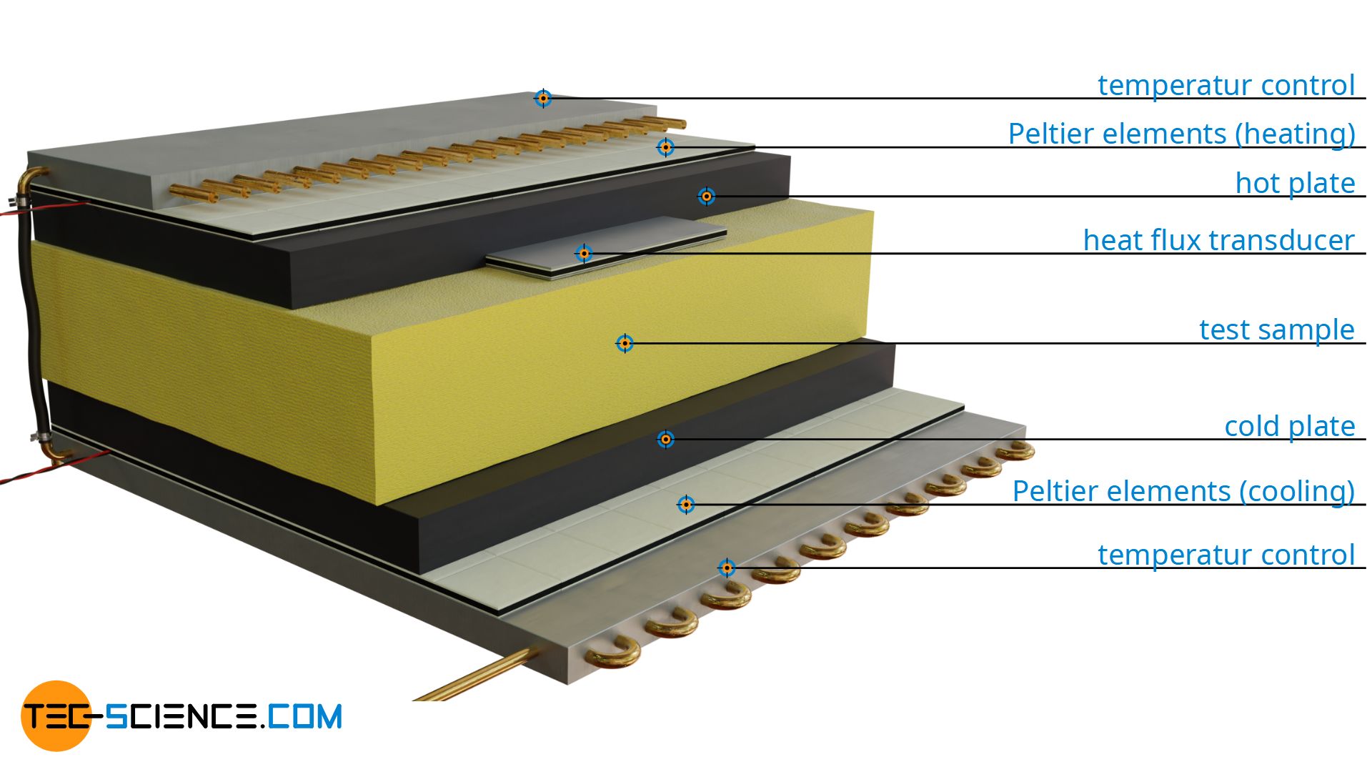
Temperature control of the plates
The temperature of the heating plate and cooling plate is usually controlled by means of so-called Peltier elements. The Peltier elements are connected to each other by a common temperature control system. In principle, such Peltier elements use the Seebeck effect, only in reverse. With the Seebeck effect, a voltage is created due to a temperature difference in a metal. In a closed circuit, a current can thus be generated from a heat flow (caused by the temperature difference). In this way, the Seebeck effect converts heat energy into electrical energy.
However, this effect can also be reversed: A current then causes heat and thus a temperature difference. This reversal effect is also known as the Peltier effect (thermoelectric effect). Strictly speaking, the Peltier effect does not correspond exactly to the reversal of the Seebeck effect. While the Seebeck effect describes the generation of a voltage due to a heat flow (temperature difference), the cause of the Peltier effect is not a voltage but a current. The Peltier effect therefore only occurs when a current is present, not when a voltage is applied.
The Peltier element thus provides a temperature difference in response to a current. This temperature difference refers to the two opposite sides of the Peltier element. So one side becomes hot, the other cold. If one of the two sides is exposed to a certain reference temperature (e.g. the temperature of a temperature-controlled system), then such a Peltier element can be used to either cool or heat, depending on which side is exposed to the reference temperature. In this way, heating is achieved on one side of the material sample. On the opposite side, where the Peltier element is installed rotated by 180°, cooling is achieved. In this way, a temperature difference is obtained to drive the heat flow through the test sample.
Heat flow measurement
Now only the heat flow rate has to be measured to determine the thermal conductivity. A heat flow cannot be measured directly like a length or a temperature. Therefore Peltier elements are used again, but this time, however, they are used in reverse. As a result of a heat flow, a temperature difference occurs at the Peltier element, which results in a voltage according to the Seebeck effect.
This voltage serves as a measuring signal for the strength of the temperature difference. The greater the temperature difference, the greater the voltage. Since the temperature difference is proportional to the heat flow according to equation (\ref{a}), the voltage is a direct measure of the rate of heat flow. Now only the exact relationship between the measuring signal and the heat flow rate needs to be clarified. This is achieved by means of a calibration using a reference sample whose thermal conductivity is known.
Thus, if the thermal conductivity of a reference sample is known, the reference heat flow Q*ref passing through it is determined by the temperature difference ΔTref, the sample thickness Δxref and the area A (area of the Peltier element). This heat flow is now assigned to the measuring signal of the Peltier element. If, for example, a heat flow rate of 2.5 W is obtained for the reference sample at an indicated voltage of 1 V, then the heat flow through an unknown sample at a voltage of 2 V is 5 W (assuming linearity). Using this heat flow rate, the thermal conductivity of the unknown test sample can then be determined according to equation (\ref{b}).
Note: If a Peltier element is used in the manner described above, heat is converted into electricity, so to speak. In this case, such a Peltier element is also called a heat flux transducer or heat flux sensor. After a calibration, the heat flux transducer is used directly as a heat flux meter. This is why this methods for determining thermal conductivity is called Heat-Flux-Meter method (HFM).
Pros and cons of the HFM method
As already explained, a Peltier element can be used to measure heat flows by calibration with a reference sample. However, a linear dependency between heat flow and measuring signal is assumed. Strictly speaking, however, this is not exactly given, i.e. with twice the voltage, the heat flow rate is not always exactly twice as large. To keep the error of this non-linearity as small as possible, the thermal conductivity of the reference sample and the geometric dimensions should correspond as closely as possible to the values of the actual specimen. If in doubt, the measurement must then be repeated with another reference material whose thermal conductivity is closer to the value measured previously.
The calibration of the Heat-Flow-Meter already brings with it an uncertainty of measurement. This leads to the fact that the measurement inaccuracy in the determination of the thermal conductivity is usually greater in the Heat-Flow-Meter method than in the Guarded-Hot-Plate method (GHP). Especially with thin samples, the influence of errors is even greater due to thermal radiation. On the other hand, HFM apparatuses are usually less expensive than GHP apparatuses.
The HFM method is therefore used, for example, in production monitoring for series production, since the measuring signal provided by the Heat-Flow-Meter can be processed directly digitally. The measuring range of the thermal conductivity values is comparable to the GHP method, but is usually limited to temperatures between -50 °C and +150 °C.
In contrast to the GHP method, the HFM method is a so-called relative measurement method (comparative measurement method), since the thermal conductivity is determined by means of calibration of a reference sample and not directly (absolute measurement method).
")


")

