In this article, learn more about the calculation of volume, temperature, work, and heat in an isobaric process in a closed system.
A change of state of a gas in which the pressure does not change is also called an isobaric process. This means that the same pressure applies to all the states through which the gas passes between the initial and final state.
How to achieve an isobaric process
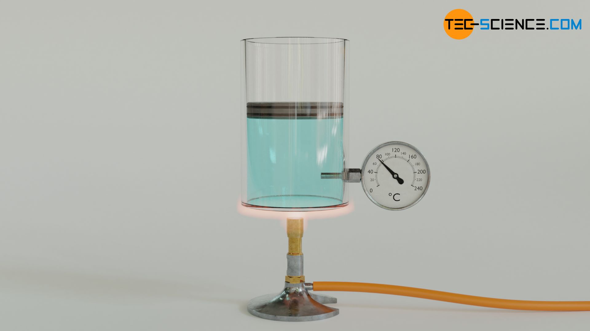
An isobaric change of state in a closed system can be realized by a vertically oriented cylinder filled with a gas and closed by a piston. The piston can be loaded with a constant weight to increase the pressure if required. If the gas is now heated, the gas expands and pushes the piston upwards. The gas pressure inside the cylinder results only from the constant ambient pressure and the constant weight forces acting on the piston. This is because, as the gas expands, there must be a balance of forces between the gas pressure acting from the inside of the cylinder on one side of the piston and the forces acting from the outside of the cylinder on the other side of the piston – at least when the piston is raised at a constant speed.
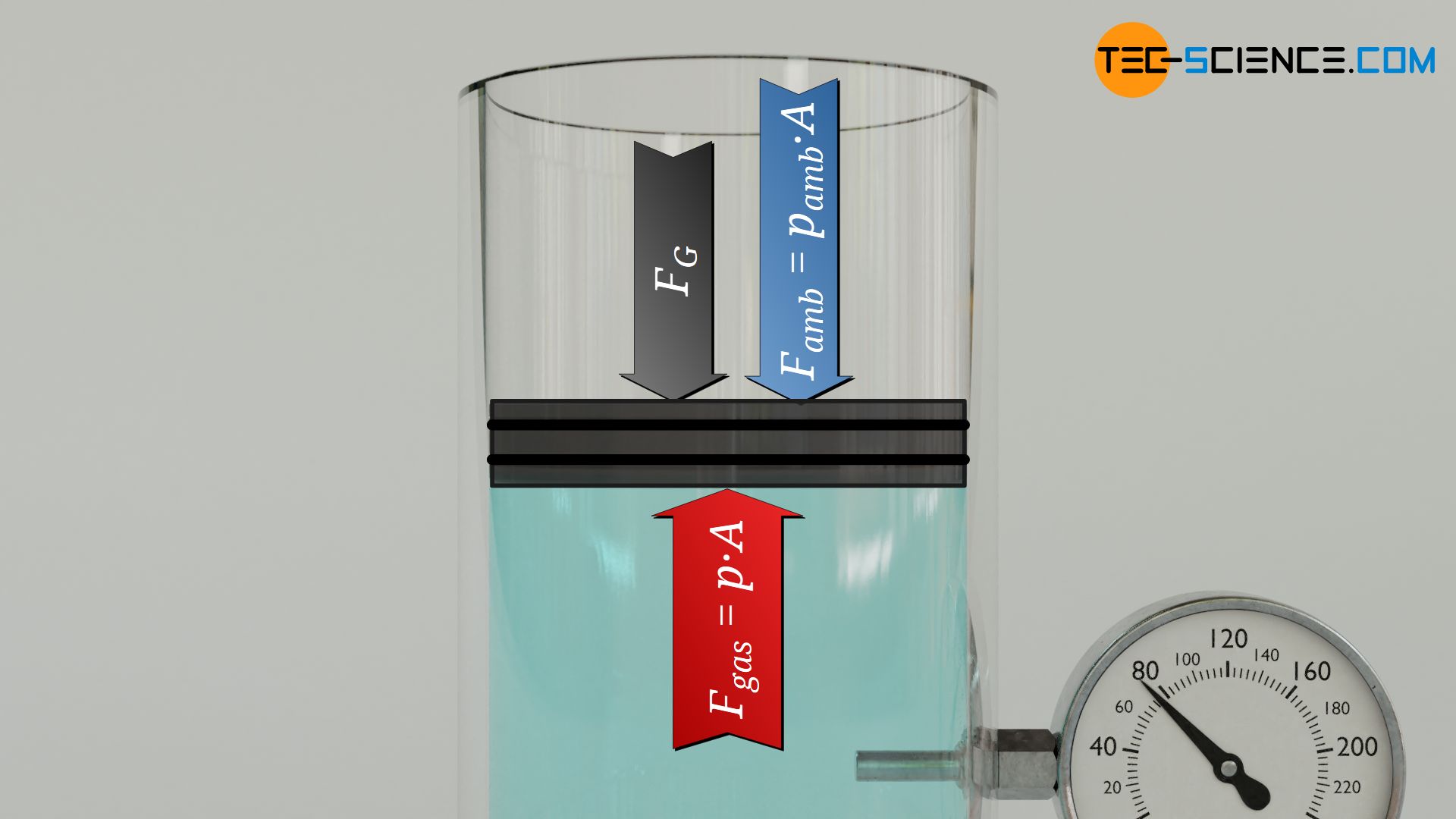
The “external” forces can therefore be used to determine the “internal” force of the gas, and with the piston area A finally the gas pressure p. In the present case, the “external” force is on the one hand the weight force FG of the piston (including any weights attached to the piston). On the other hand, the force Famb also acts on the piston, which is due to the ambient pressure! This ambient force can be calculated from the ambient pressure pamb and the piston area A (Famb=pamb⋅A). By setting up the balance of forces, the acting force of the gas Fgas can be calculated:
\begin{equation}
F_\text{gas} \overset{!}{=} F_\text{G} + F_\text{amb} ~~~~~\text{balance of forces} \\[5px]
F_\text{gas} = F_\text{G} + p_\text{amb} \cdot A \\[5px]
\end{equation}
Thus, the gas acts with this force Fgas on the piston surface A, which leads to the following gas pressure p:
\begin{equation}
\label{de}
\underline{p} = {F_\text{gas} \over A} = {{F_\text{G} + p_\text{amb} \cdot A} \over A} = \underline{ {F_\text{G} \over A} + p_\text{amb}}
\end{equation}
Equation (\ref{de}) shows that the gas pressure obviously depends only on quantities which do not change during the entire thermodynamic process. The gas pressure thus always remains constant for the entire change of state. Therefore, the lifting of the piston is an isobaric process.
Illustration in the volume-pressure diagram
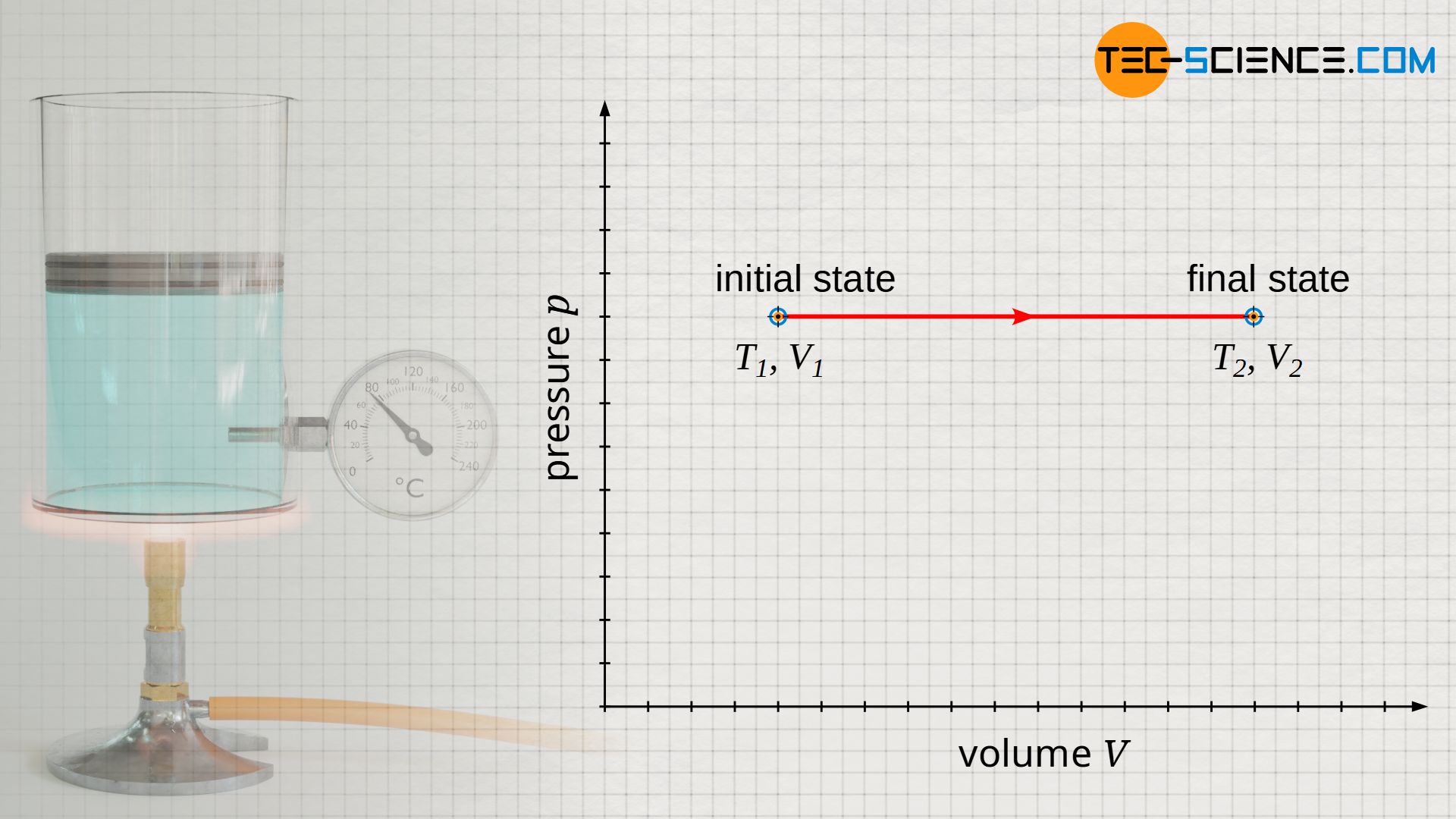
If the piston is moved upward while heat is supplied, the gas heats up from T1 to T2 and the gas volume increases from V1 to V2 at constant pressure. If this process is illustrated in a volume-pressure diagram, a horizontal line results from the initial volume V1 to the final volume V2 at constant pressure p.
Relationship between volume and temperature (law of Gay-Lussac)
In an isobaric process, the volume increases proportionally with the temperature. However, this statement only applies if the temperature is given in the unit Kelvin. A doubling of the temperature in an isobaric heating thus also means a doubling of the gas pressure. This proportionality is equivalent to the statement that volume and temperature always have a constant ratio. This phenomenon is also referred to as law of Gay-Lussac:
\begin{align}
&V \sim T ~\Rightarrow~ {V \over T} = \text{constant}
\end{align}
Any two states within an isobaric process are consequently linked by the constant quotient of volume and temperature:
\begin{equation}
\label{p}
\boxed{ {V_1 \over T_1} = {V_2 \over T_2} } ~ \text{law of Gay-Lussac}
\end{equation}
Calculation of the change in internal energy
For ideal gases, the change in internal energy ΔU results independent of the thermodynamic process only on the basis of the temperature change ΔT=T2-T1:
\begin{equation}
\label{du}
\boxed{ \Delta U = c_\text{v} ~ m ~ \left(T_2-T_1 \right)} = c_\text{v} ~ m ~ T_1 ~ \left({T_2 \over T_1}-1 \right) = c_\text{v} ~ m ~ T_1 ~ \left({V_2 \over V_1}-1 \right)
\end{equation}
In this equation cv denotes the specific heat capacity and m the mass of the gas. If equation (\ref{p}) is used in equation (\ref{du}) after factoring out the temperature T1, the change in internal energy can also be expressed in terms of the volume ratio V2/V1 (=T2/T1).
Calculation of the pressure-volume work
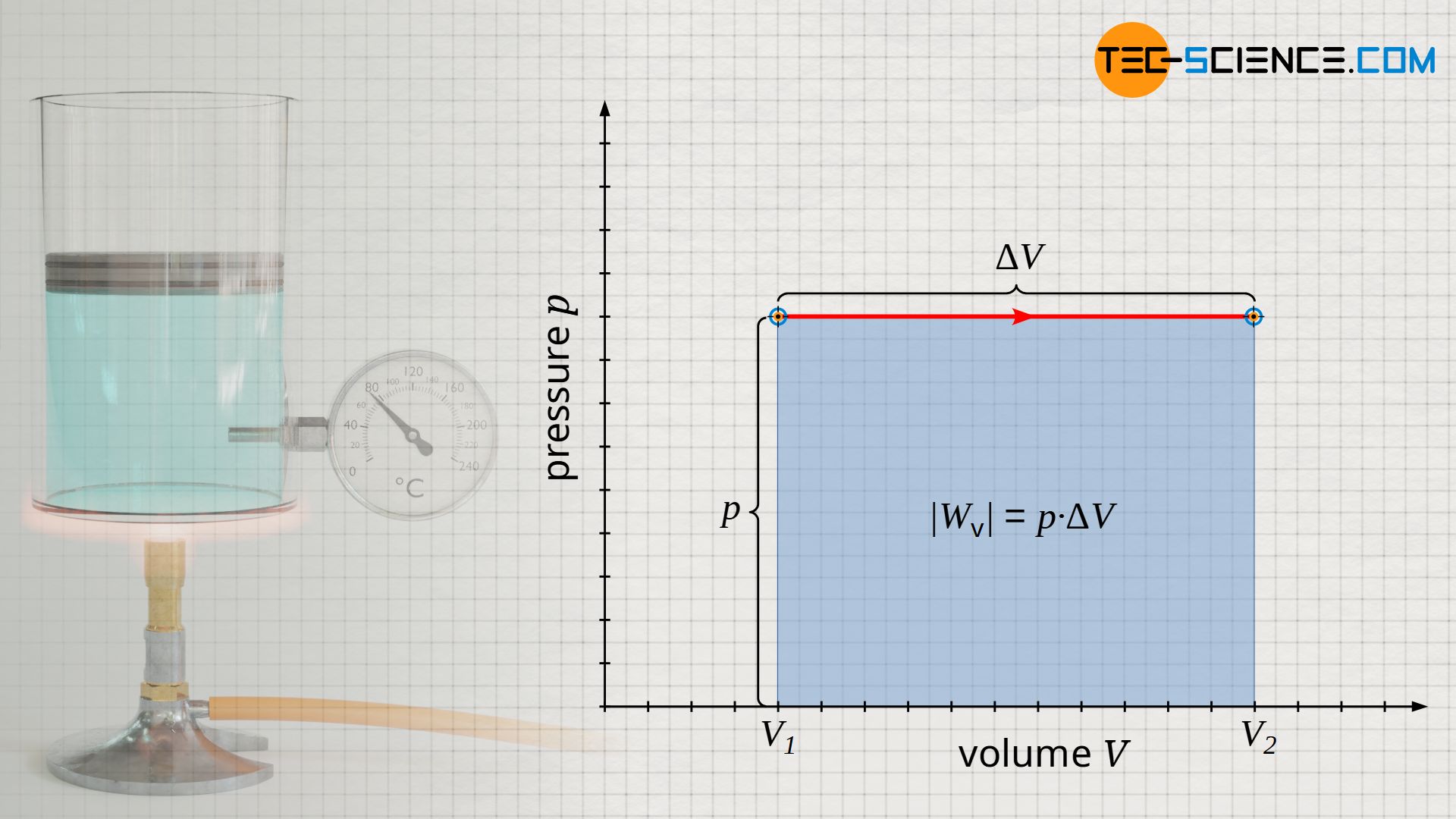
The pressure-volume work done on the gas or by the gas is relatively easy to determine for the isobaric process, since the area under the curve in the p(V) diagram is rectangular (note that the area under the process curve generally represents the pressure-volume change work!). The rectangular area is determined by the “height” p and the “width” ΔV=V2-V1. Taking into account the sign convention, the following formula applies to calculate the pressure-volume work Wv of an isobaric process:
\begin{equation}
\label{w}
\boxed{ W_\text{v} = – p \cdot \Delta V = – p \cdot \left(V_2 – V_1 \right) }
\end{equation}
Note: The negative sign results from the sign convention, since with an increase in volume (expansion: ΔV>0) the gas obviously does work on the piston and the pressure-volume work is to be counted negatively (Wv<0). Conversely, a reduction in volume (compression: ΔV<0) is to be counted positively, since work is done on the gas (Wv>0).
The pressure-volume work can be determined not only by the difference in volumes, but also by the difference in temperatures. Some transformations are necessary for this, using the ideal gas law (where Rs denotes the specific gas constant.):
\begin{align}
\label{z}
\boxed{p \cdot V= R_\text{s} \cdot m \cdot T} ~~~\text{ideal gas law}
\end{align}
\begin{align}
\label{www}
W_\text{v} &=- p \cdot \left(V_2 – V_1 \right) \\[5px]
&=- \left( p ~ V_2 – p ~ V_1 \right) ~\text{ where }~ \underbrace{p~V=R_\text{s}~m~T}_{\text{ideal gas law}} ~\text{:}~ \\[5px]
&= – \left( R_\text{s} ~ m ~ T_2 – R_\text{s} ~ m ~ T_1 \right) \\[5px]
&= -R_\text{s} ~ m ~ \left(T_2 – T_1 \right)
\end{align}
The pressure-volume work Wv can therefore also be determined from the difference between the final and initial temperature of the isobaric process:
\begin{equation}
\label{wvv}
\boxed{W_\text{v} = – R_\text{s} ~ m ~ \left(T_2 – T_1 \right)}
\end{equation}
Calculation of the transferred heat
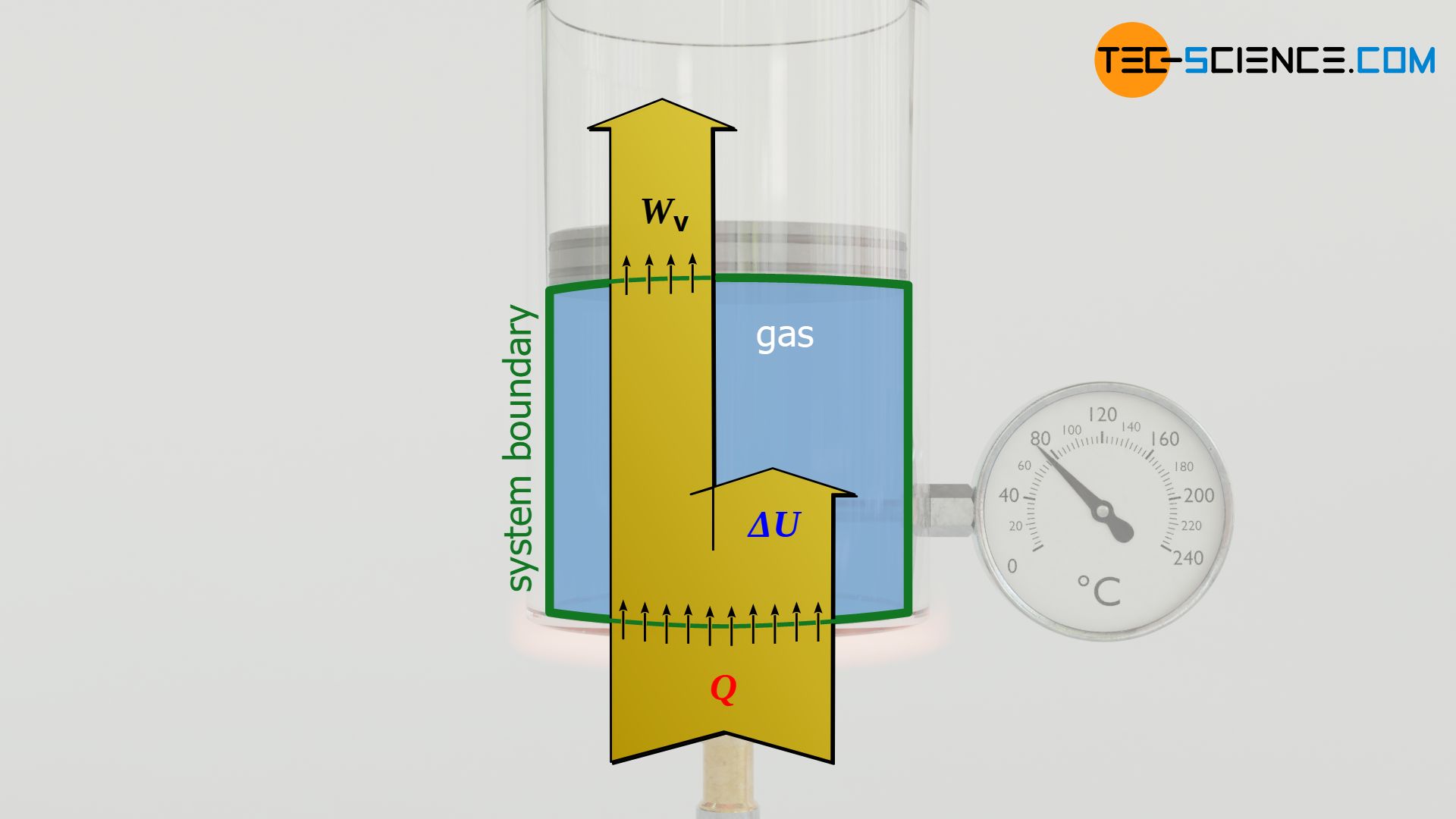
Finally, the first law of thermodynamics can be used to calculate the heat energy Q absorbed or released by the gas for an isobaric process. The transferred heat is determined from the difference between the change in internal energy ΔU and the pressure-volume work Wv:
\begin{align}
&\boxed{W_\text{v} + Q = \Delta U} ~~~ \text{first law of thermodynamics} \\[5px]
\end{align}
\begin{align}
Q &= \Delta U – W_\text{v} \\[5px]
&= c_\text{v} ~ m ~ \left(T_2-T_1 \right) + R_\text{s} ~ m ~ \left(T_2 – T_1 \right) \\[5px]
&= \underbrace{[c_\text{v}+R_\text{s}]}_{=c_\text{p}} ~ m ~ (T_2-T_1)
\label{eq:9885}
\end{align}
At this point, the constant quantities cv and Rs can be combined to form a new constant cp, resulting in the following relationship between the transferred heat Q and the temperature change:
\begin{equation}
\label{q}
\boxed{ Q = c_\text{p} ~ m ~ (T_2-T_1)} ~\text{where}~ \boxed{c_\text{p}=c_\text{v}+R_\text{s}}
\end{equation}
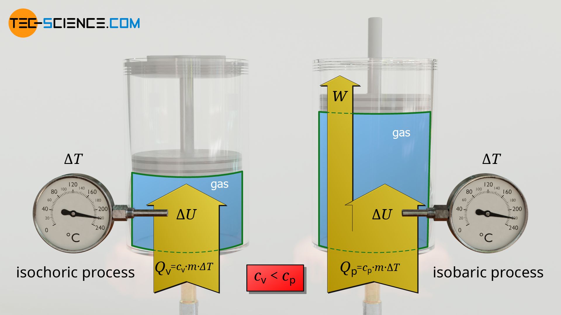
The reason why these constants are combined to form a new constant becomes apparent when comparing the upper formula with the formula for the transferred heat of an isochoric process:
\begin{align}
\label{eq:6667}
Q_\text{v} &= c_\text{v} ~ m ~ (T_2-T_1) ~~ \text{isochoric process} \\[5px]
Q_\text{p} &= c_\text{p} ~ m ~ (T_2-T_1) ~~ \text{isobaric process}\\[5px]
\end{align}
The constant cv can be interpreted as the specific heat capacity of the isochoric process and cp as the specific heat capacity of the isobaric process. In this way, the analogous relationships between the transferred heat and the temperature change now arise in both the isobaric and the isochoric process.
The transferred heat according to equation (\ref{q}) can also be expressed by the ratio of final and initial volumes for a given initial temperature T1:
\begin{equation}
Q= c_\text{p} ~ m ~ \left(T_2-T_1 \right) = c_\text{p} ~ m ~ T_1 ~ \left({T_2 \over T_1}-1 \right) = c_\text{p} ~ m ~ T_1 ~ \left({V_2 \over V_1}-1 \right)
\label{eq:7052}
\end{equation}
Note on the specific heat capacities
Note that it is evident from equation (\ref{q}) that the isobaric heat capacity cp is always greater than the isochoric heat capacity by the value of the specific gas constant Rs. This means that more heat has to be transferred in an isobaric process than in an isochoric process if the same temperature change is to be achieved.
The reason for this is that in an isobaric process the supplied heat energy Q does not completely benefit the change in internal energy ΔU and thus the temperature increase. This is because part of the supplied heat is converted into pressure-volume work Wv. For this reason, more heat energy must be supplied so that, minus this pressure-volume work, sufficient energy is still available for the change in internal energy and thus for the temperature increase.
For further information, see also the article Specific heat capacity of gases.
")


