The work which is required to maintain the flow against the different static pressures between inlet and outlet of an open system is referred to as flow work.
Introduction
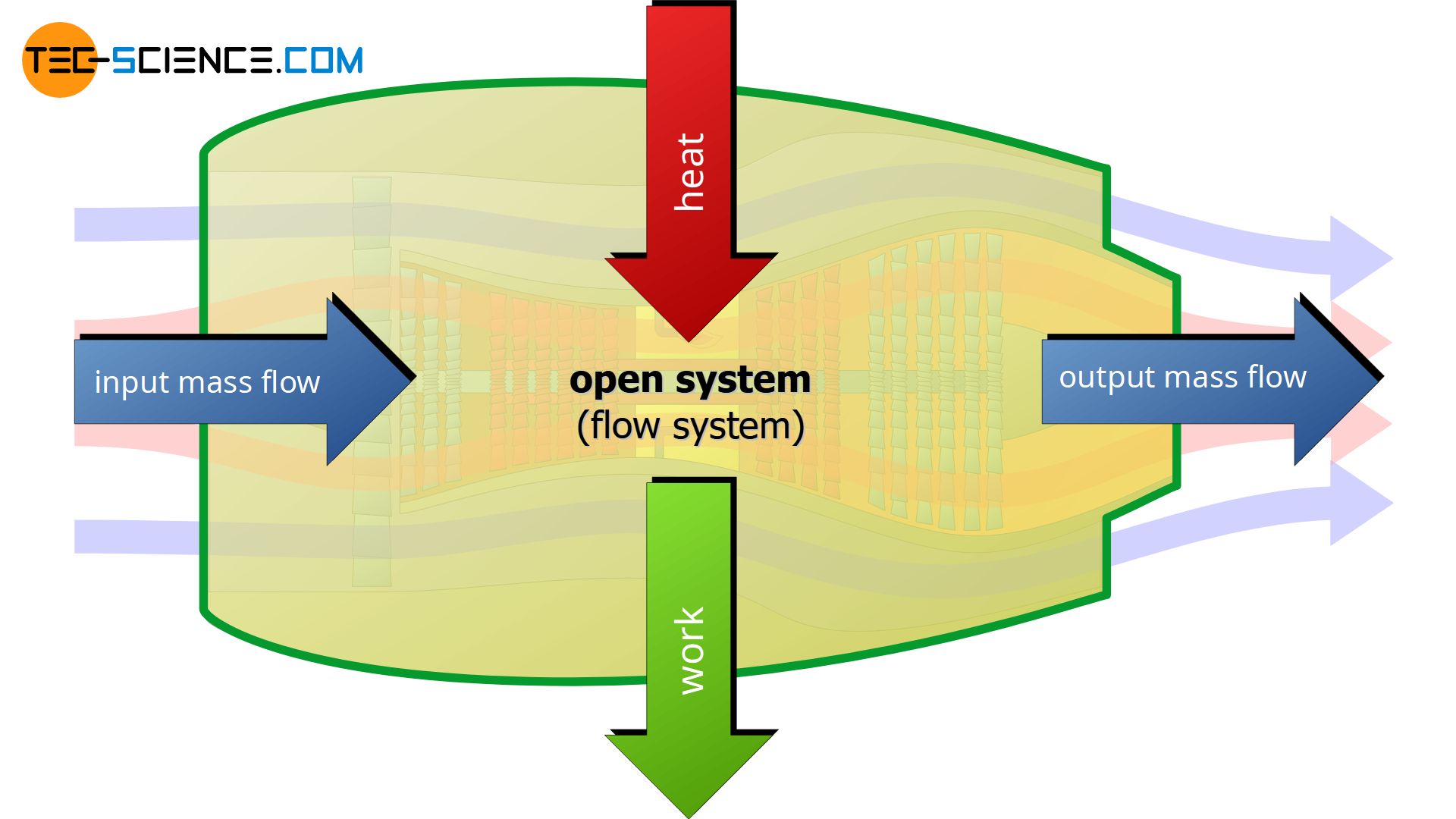
Many thermodynamic processes take place in open systems. In contrast to closed systems, in open systems there is not only a transfer of energy as heat or work but also a mass exchange with the surroundings. This is the case, for example, with pumps, compressors, aircraft engines or gas turbines. In these systems, mass enters the system from one side and leaves on the other.
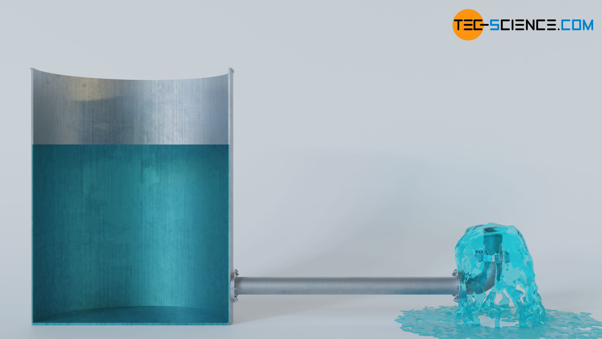
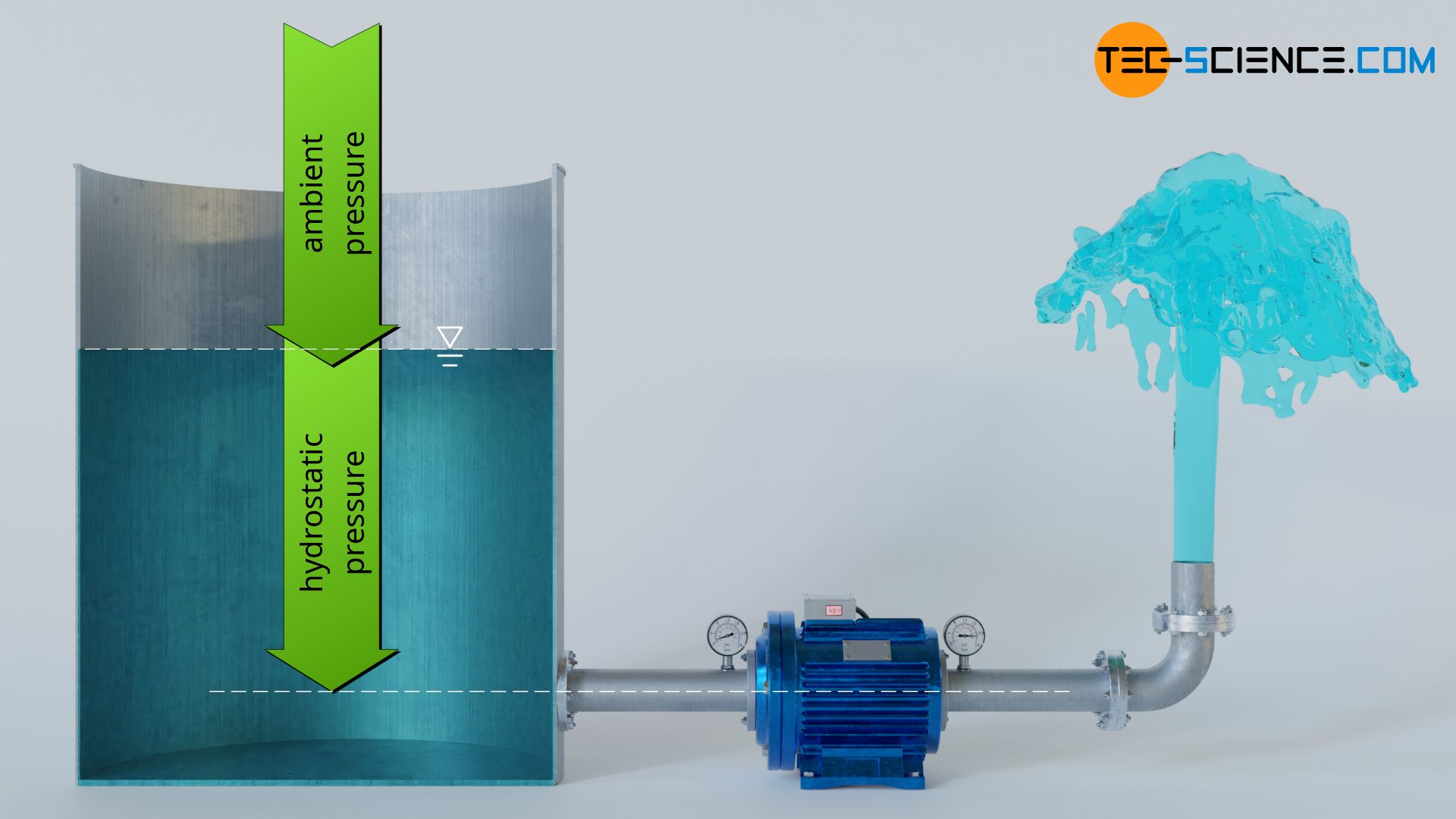
To push this mass through an open system, energy is required. This will be illustrated in the following using the example of a water pump. First, we consider the case without a pump, where water flows from a tank through a horizontal pipe. In this case, the water exits the pipeline at a relatively slow speed.
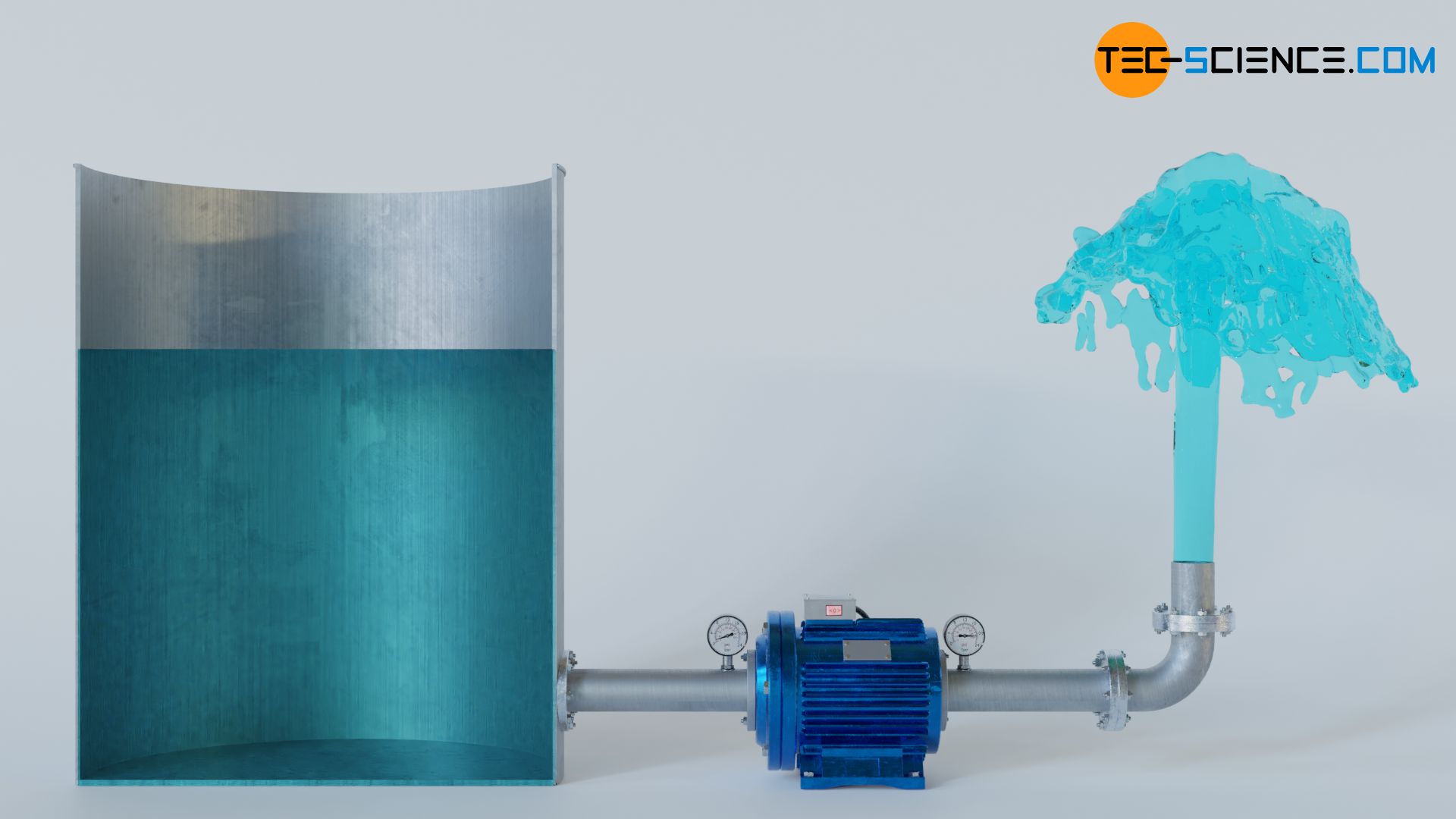
Now a pump is installed in the pipeline. Similar to a ship’s propeller, the pump contains a rotating impeller (see also the article on centrifugal pumps). This impeller puts the water in the front part of the pump or pipeline under high pressure. Thus, the water flows faster through the pipeline and increases the mass flow, so that more water can be pumped in the same time than without a pump.
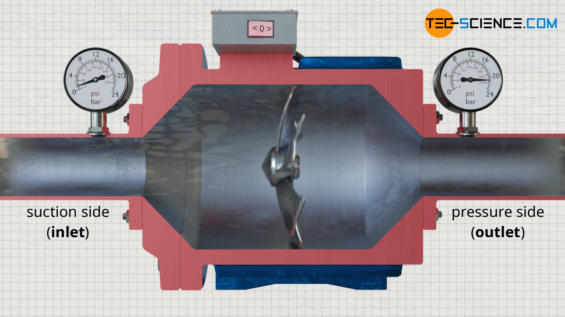
The water pump is a typical open system into which mass flows at the pump inlet at relatively low pressure and is pushed out again at higher pressure at the pump outlet. Under simplified, frictionless conditions, the question of what work the pump has to do in order to deliver a certain mass of water will now be discussed. For this purpose, the energetic processes at the inlet and outlet of the pump will be examined in more detail.
Energy with which the fluid is pushed in
Just before entering the pump, the water is under a certain pressure p1. In this case, this pressure is caused on the one hand by the hydrostatic pressure of the water column in the tank and on the other hand by the ambient pressure of the air acting on the water surface. Both pressures push the water into the pump on the so-called suction side.
Note: Not the pump sucks the water by a negative pressure, as one might think by the term suction side, but the ambient pressure and the hydrostatic pressure push the water into the pump! Because even if the pump would create a vacuum at the inlet, no water could be pushed into the pump without ambient pressure and hydrostatic pressure (see also the article How does a drinking straw work?).
Based on the acting pressure p1 at the inlet and the cross-sectional area A1, the force F1 with which the water is pushed into the pump by the surroundings can be determined:
\begin{align}
\label{7481}
&F_1 = p_1 \cdot A_1
\end{align}
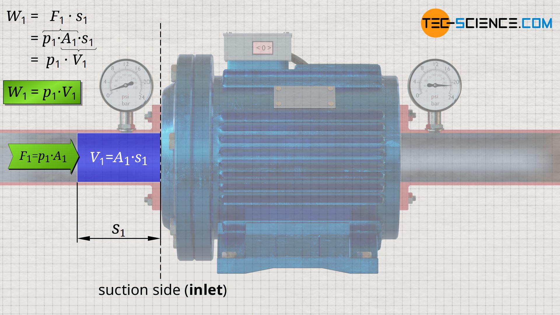
With this force F1, a certain amount of water located directly in front of the inlet is pushed into the pump within a certain time. One can also imagine a piston that pushes the water into the pump with the force F1 along the distance s1. From the product of force and distance, the energy W1 can be determined, with which the surroundings (“piston”) pushes the water mass into the pump. This energy corresponds to the work done by the surroundings on the water mass:
\begin{align}
&W_1 = F_1 \cdot s_1 = p_1 \cdot \underbrace{A_1 \cdot s_1}_{=V_1} = p_1~V_1 \\[5px]
\label{5792}
&\boxed{W_1 = p_1 \cdot V_1} ~~~~~\text{pushed-in energy}
\end{align}
The product of displacement s1 and cross-sectional area A1 in the above equation equals the water volume V1 that is pushed into the system.
The energy with which a fluid is pushed through a cross-section results from the product of pressure and volume!
Numerical example
If the ambient pressure is assumed to be 1 bar and the height of the water column is assumed to be 1 m, a (hydrostatic) pressure of 0.1 bar acts in addition to the ambient pressure of 1 bar. In total, the water is thus pushed into the pump with a total pressure of p1=1.1 bar. Within a time of t = 4 s, m = 2 kg of water flows through the pump inlet. With a water density of 999.25 kg/m³, the volume of this water mass is V1 =2.0015 liters. This volume of water is pushed into the pump by the surroundings with an energy of W1 = 220 J:
\begin{align}
&\underline{W_1} = p_1 \cdot V_1 = 1.1 \cdot 10^5\frac{\text{N}}{\text{m²}} \cdot 2.0015 \cdot 10^{-3} \text{ m³} = \underline{220 \text{ J}}
\end{align}
Energy with which the fluid is pushed out
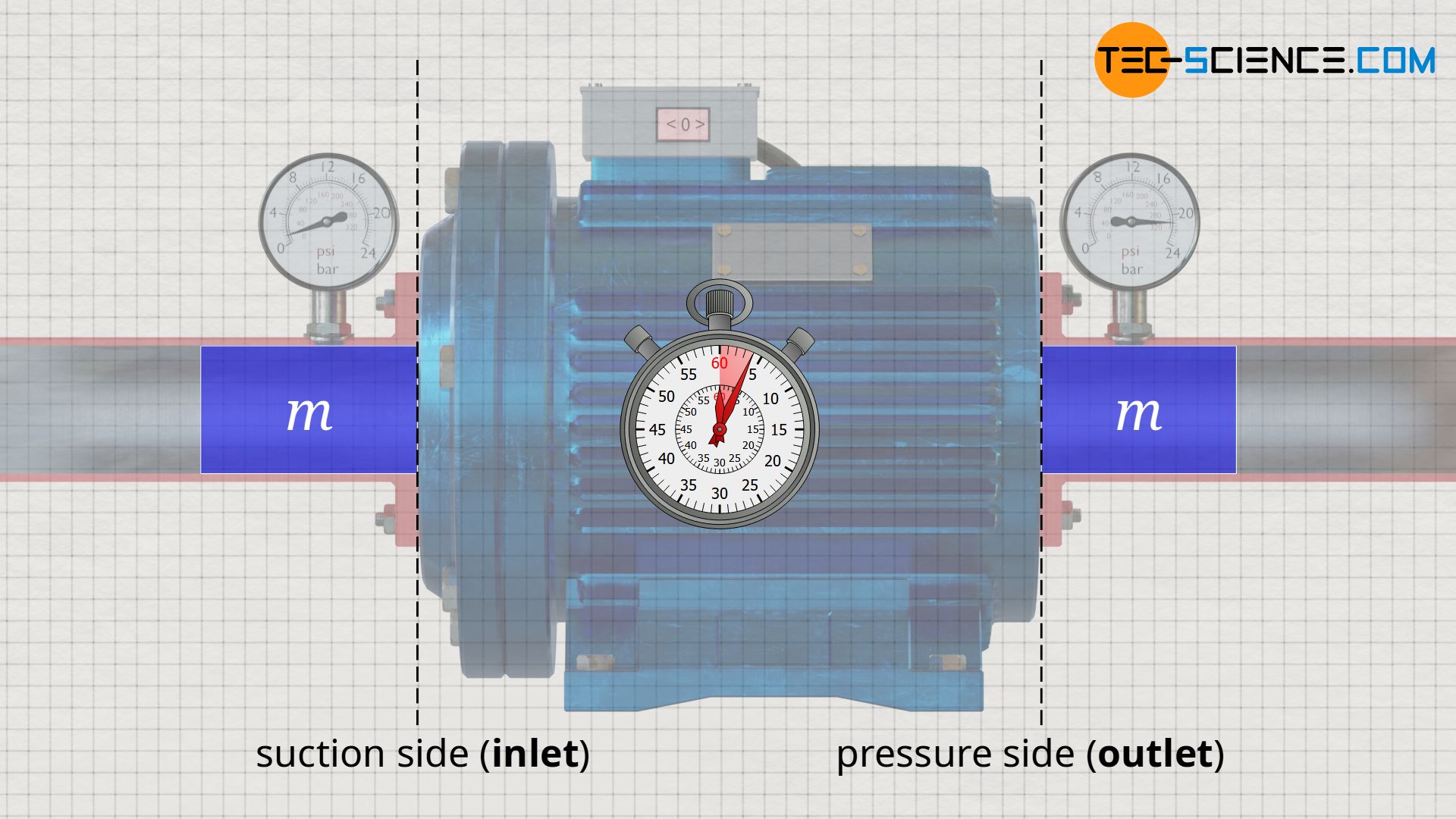
After the energetic process at the pump inlet has been clarified, the energetic process at the pump outlet, the so-called pressure side, will now be considered in more detail. Basically, the same mass of water is pushed out at the outlet as flows in at the inlet within a certain time, because in the steady state no water can accumulate in the pump nor be annihilated (law of conservation of mass). The conservation of mass applies not only to incompressible fluids such as liquids, but also to compressible substances such as gases!
In the previous section, it was calculated on the basis of the numerical example that the surroundings push the water with an energy of 220 J into the pump. If the pump were switched off, the water would be pushed through the pump with this energy and would only leave the pump again with this energy (flow and friction losses neglected). However, the pump now causes an increase in pressure by the rotating impeller. The water is therefore pushed out of the pump at a higher pressure than it was pushed into the pump.
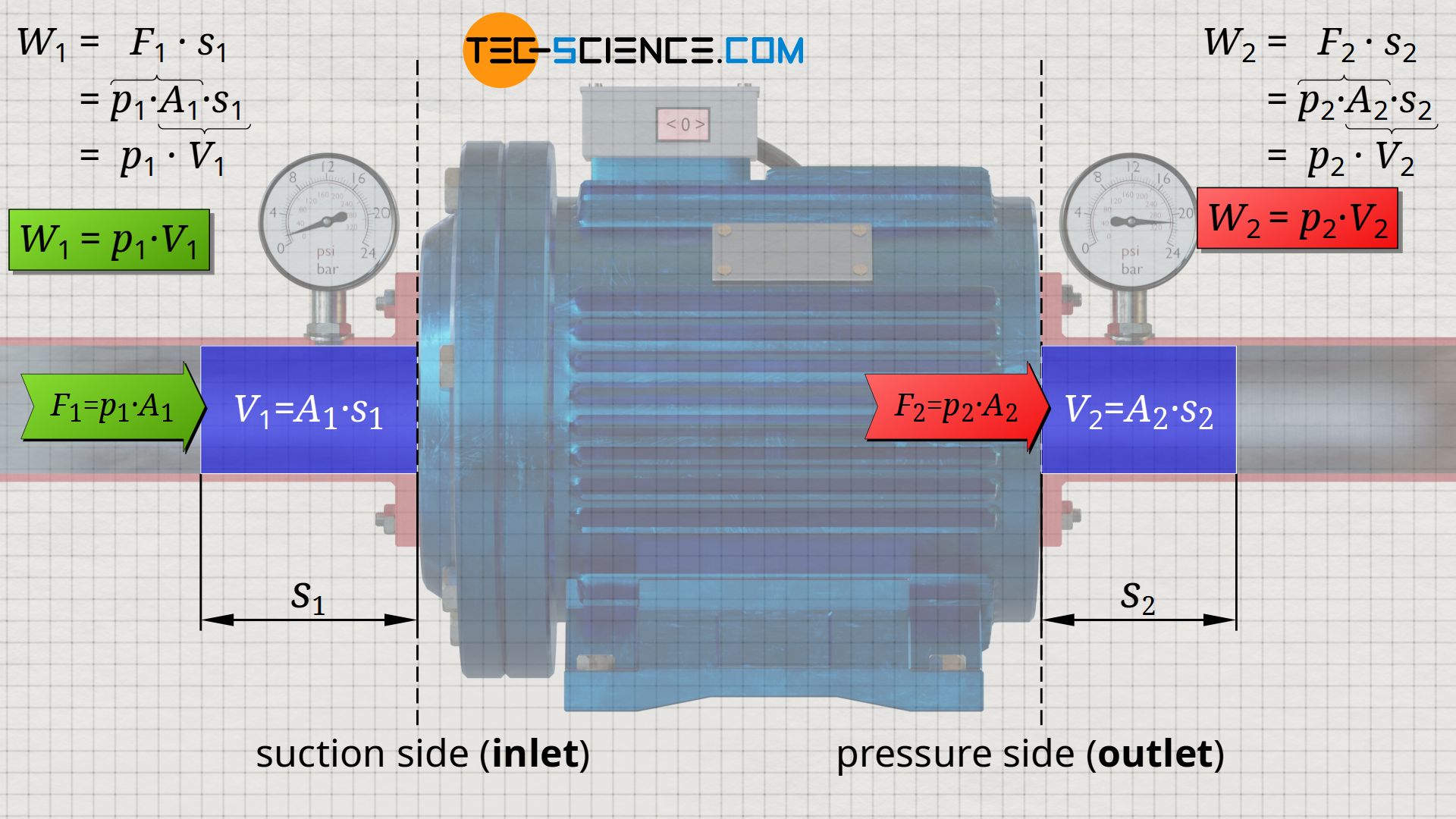
The water therefore exits the pump with a greater force, which results in an increase in the energy with which the water flows out. This energy at the pump outlet can be derived analogously to equation (\ref{5792}). The water is pushed out with the force F2=p2⋅A2 along the distance s2 through the cross-section A2 at the pump outlet. This leads to the following energy W2 with which the water ist pushed out:
\begin{align}
&W_2 = F_2 \cdot s_2 = p_2 \cdot \underbrace{A_2 \cdot s_2}_{=V_2} = p_2 \cdot V_2 \\[5px]
\label{3018}
&\boxed{W_2 = p_2 \cdot V_2} ~~~~~\text{pushed-out energy}
\end{align}
Numerical example
If, for example, the pump generates a pressure increase of Δp = 20 bar, the water pressure increases from p1 = 1.1 bar at the pump inlet to a total of p2 = 21.1 bar at the pump outlet. The increased pressure in turn affects the displaced volume. Due to the conservation of mass, the masses pushed in and out within a certain time are identical, but the respective volumes differ due to the different pressures. The water mass of 2 kg no longer has a volume of V1 = 2.0015 liters at the pump outlet, but a slightly lower volume of V2 = 1.9996 liters due to the greater pressure.
At a pressure of p2=21.1 bar and a volume of V2 =1.9996 liters, the energy with which the water mass of 2 kilograms is pushed out is W2 = 4220 J:
\begin{align}
&\underline{W_2} = p_2 \cdot V_2 = 21.1 \cdot 10^5 \frac{\text{N}}{\text{m²}} \cdot 1.9996 \cdot 10^{-3} \text{ m³} = \underline{4220 \text{ J}}
\end{align}
If one compares the energy of W1 = 220 J, with which the water ist pushed in, with the energy of W2 = 4220 J, with which the water is pushed out, it becomes clear that the pump obviously ensures that the entering water mass is pushed out with greater energy than it was pushed in by the surroundings. Thus, the water flows out at the end of the pipe with greater power compared to the case without pump.
Note: Due to the incompressibility of liquids, the small volume changes caused between the inlet and outlet of an open system can often be neglected. In the case of compressible liquids such as gases, however, the volume changes can be very large and thus significant, since further energy is then required to compress the volume (pressure-volume work must be done on the gas). This will be discussed in more detail in the article Flow process work in open systems.
Energy to push through (flow energy)
The 4000 J higher energy with which the water flows out of the pump compared to the energy at the pump input can of course only be due to the pump itself. The energy of 4000 J corresponds to the work that the pump must perform on the flowing liquid. It is supplied to the pump in the form of electrical energy and transferred to the water by the impeller. This consideration is highly simplified and will be discussed in more detail in the article Flow process work in open systems and Shaft work in open systems.
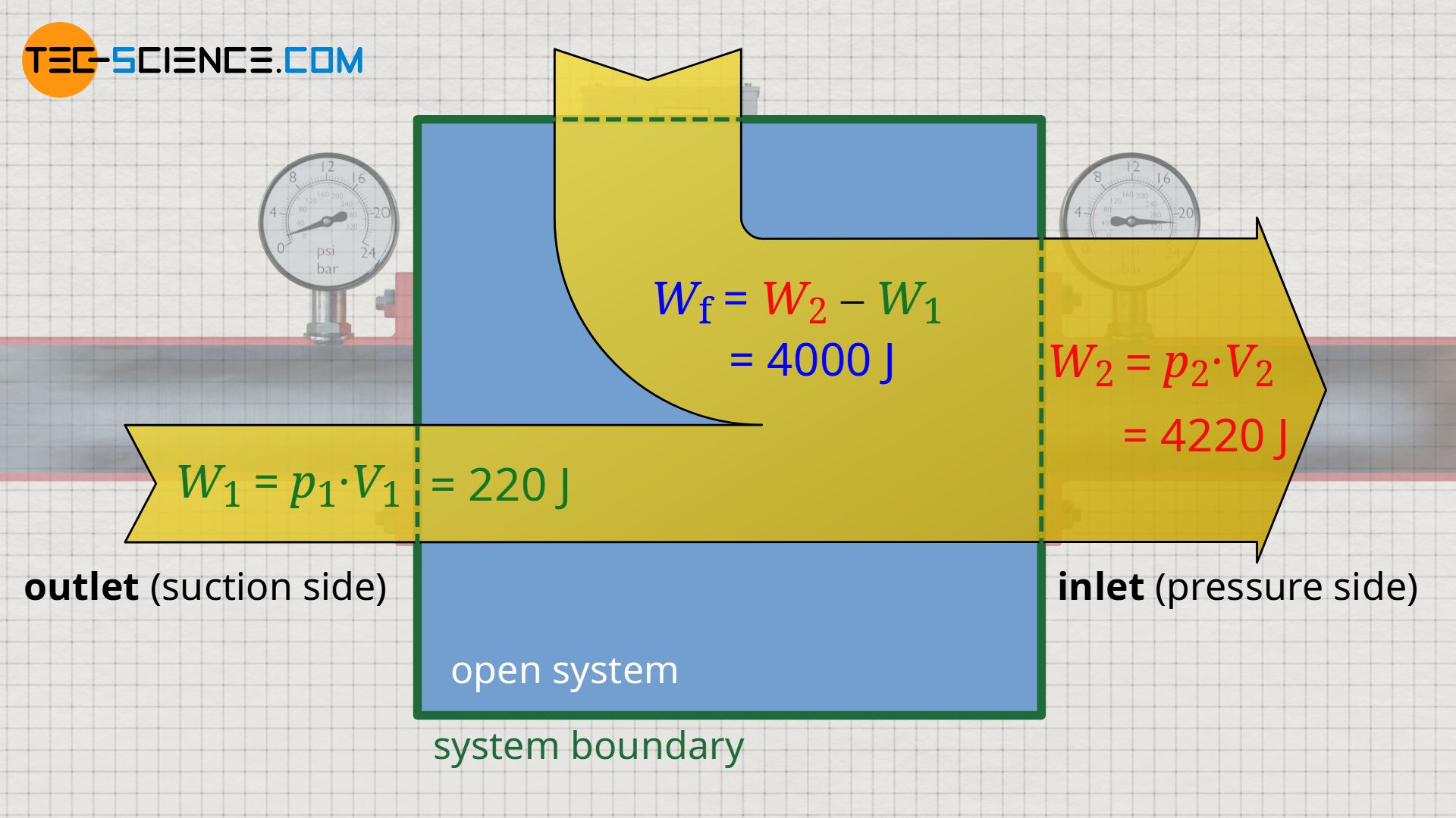
However, this simplified approach shows that the work of the pump is calculated from the difference between the push-out energy W2 and the push-in energy W1. In an open system, this work is generally referred to as flow work (Wf):
\begin{align}
\label{9372}
&W_\text{f} = W_2 – W_1 \\[5px]
\label{7076}
&\boxed{W_\text{f} = p_2~V_2 – p_1~V_1 } = \Delta \left(p~V \right) ~~~~~\text{flow work}
\end{align}
The work which is required to maintain the flow against the different static pressures between inlet and outlet of an open system is referred to as flow work!
Equation (\ref{7076}) shows that the flow work of an open system is determined only by the state of a flowing mass just before it enters the system (p1, V1) and just after it leaves the system (p2, V2). It does not matter how exactly the flowing mass gets from the initial state 1 to the final state 2. The thermodynamic process inside the open system is therefore completely irrelevant for the determination of the flow work. Thus, the flow work is not a process quantity, as one might mistakenly think on the basis of the term work, but a state variable!
Note: Sometimes, only the individual products of pressure and volume are referred to as flow work. This is because the product p1⋅V1 is due to the pushing into the open system and the product p2⋅V2 is due to the pushing out of the open system. For didactic reasons, however, in the following the term flow work shall always mean the difference of both products according to equation (\ref{7076}), i.e. the work required to push the mass through the open system (not only in or out).
Specific flow work
The example of the pump explained in the previous sections showed that the pump has to perform a flow work of 4000 J for pumping a water mass of 2 kg. If the pump is to deliver 10 times the water mass of 20 kg, then the pump must perform a 10-fold work of 40,000 J in total.
This example shows that the flow work depends on the mass flowing through an open system. For this reason, it makes more sense in open systems not to relate the amount of energy converted to an arbitrary mass of 2 kg or 20 kg, but always to 1 kg. Thus, the water pump must deliver an energy of 2000 J per kilogram of water flowing through it. Such a quantity related to the mass is also referred to as a specific quantity. In this case, it is called specific flow work and is 2000 J/kg.
The specific flow work wf is generally determined as the quotient of the flow work Wf and the associated mass m:
\begin{align}
\label{3475}
&\boxed{w_\text{f} = {W_\text{f} \over m}} ~~~[w_\text{f}] = \frac{\text{J}}{\text{kg}} ~~~~~\text{specific flow work} \\[5px]
\end{align}
With the definition of the flow work as the difference of the products of pressure p and volume V, it can be seen that the specific flow work can also be calculated by the specific volumes v:
\begin{align}
&w_\text{f} =\frac{W_\text{f}}{m} = \frac{p_2 \cdot V_2 – p_1 \cdot V_1}{m} = {p_2 \cdot \underbrace{\frac{V_2}{m}}_{=v_2} – p_1 \cdot \underbrace{\frac{V_1}{m}}_{=v_1}} = p_1 \cdot v_1 – p_2 \cdot v_2 \\[10px]
\label{2070}
&\boxed{w_\text{f} = p_1 \cdot v_1 – p_2 \cdot v_2} ~~~ \text{where}~~~ \boxed{v={V \over m}} ~~~ [v]=\frac{\text{m³} }{\text{kg}} ~~~\text{specific volume} \\[10px]
\end{align}
The specific volume indicates the volume occupied by a substance with a mass of 1 kg. The specific volume v thus corresponds to the reciprocal of the mass density ρ (specific mass):
\begin{align}
\label{9579}
&\boxed{v = {1 \over \rho}} \\[5px]
\end{align}
Thus, the specific flow work can also be determined by the density of the fluid at the inlet and outlet of an open system:
\begin{align}
\label{2791}
&\boxed{w_\text{f} = \frac{p_2}{\rho_2} – \frac{p_1}{\rho_1} }~~~\text{where}~~~ \boxed{\rho= {m \over V}} ~~~ [\rho]={\text{kg} \over \text{m³}} ~~~ \text{density} \\[5px]
\end{align}
The advantage of determining the specific flow work according to equation (\ref{2791}) or (\ref{2070}) is that these equations can be applied independently of the actual mass flowing through the open system. It is completely irrelevant whether 2 kg or 20 kg of water flow through the pump.
Numerical example
In the present example, the water density at the pump inlet is ρ1 = 999.25 kg/m³ (at p1 = 1.1 bar) and at the pump outlet ρ2 = 1000.19 kg/m³ (at p2 = 21.1 bar). From these quantities, the specific flow work can be determined without having to know in advance how much mass will actually flow through the pump:
\begin{align}
& \underline{w_\text{f} } = \frac{p_2}{\rho_2} – \frac{p_1}{\rho_1} = \frac{12.1 \cdot 10^5 \frac{\text{N}}{\text{m²}} }{1000.19 \frac{\text{kg}}{\text{m³}}} – \frac{1.1 \cdot 10^5 \frac{\text{N}}{\text{m²}} }{999.25 \frac{\text{kg}}{\text{m³}}} = \underline{2000 \frac{\text{J}}{\text{kg}}} \\[5px]
\end{align}
Flow power (power of the pump)
Especially in open systems it is relatively easy to calculate the transferred power by using specific quantities. Using the example of the water pump already considered, we will assume that it delivers a water mass of m = 2 kg within a time of t = 4 s at. Thus, 0.5 kg of water flows through the pump within one second. This transferred mass per unit time is also referred to as mass flow rate. The mass flow rate is often denoted by a dot above the symbol (\(\dot{m}\)) and is generally calculated as the quotient of the mass m delivered and the respective time t:
\begin{align}
\label{7914}
\boxed{\dot{m} = \frac{m}{t}} ~~~[\dot{m}]=\frac{\text{kg}}{\text{s}} ~~~~~\text{mass flow rate} \\[5px]
\end{align}
With this mass flow rate, the power of the pump (flow power) can be determined relatively easily. According to the example, the pump is to deliver a water mass of m = 2 kg within t = 4 s. With a specific flow work of the pump of wf = 2000 J/kg, the pump then performs a total flow work of Wf = 4000 J on the 2 kg water mass; and this within a time period of t = 4 s. The quotient of transferred work Wf and time t finally results in a flow power of the pump of Pf = 1000 J/s (1000 W). In the ideal case, this would correspond to the electrical power supplied to the pump (neglecting flow or friction losses and assuming incompressibility of the water). Such a (flow) power Pf can be determined quite generally by the mass flow rate and the specific (flow) work:
\begin{align}
&P_\text{f}=\dot{W_\text{f}}= \frac{W_\text{f}}{t} = \frac{w_\text{f} \cdot m} {t} = w_\text{f}~\underbrace{\frac{m}{t}}_{=\dot{m}} \\[5px]
\label{6526}
&\boxed{P_\text{f} = w_\text{f} \cdot \dot m}
\end{align}
Equation (\ref{6526}) is not limited to the flow power, but can be generalized:
\begin{align}
\label{3679}
&\boxed{\text{Power = specific energy x mass flow rate}}
\end{align}
Outlook
As already indicated several times in this article, for incompressible fluids the flow work (or flow power) is the main work to be done by/on an open system. However, if compressible fluids such as gases are involved, then a further energy transfer takes place in an open system, since the volume must also be compressed in addition to just pushing the volume through (pressure-volume work). This is discussed in more detail in the article Flow process work in open systems.

")

