The flow process work done in open systems can be interpreted as the pressure-volume work of closed systems.
Flow process work
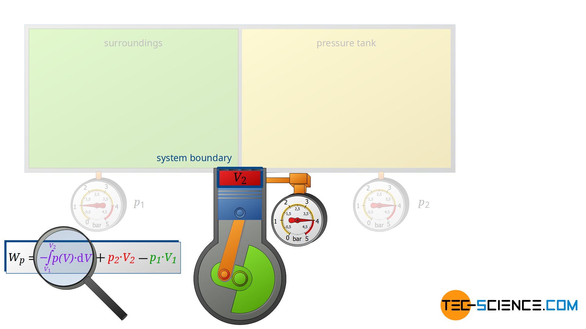
As explained in detail in the article on flow process work, the flow process work Wp is made up of the sum of flow work Wf and pressure-volume work Wv:
\begin{align}
\label{5715}
&W_\text{p} = W_\text{v} + W_\text{f} \\[5px]
\label{4461}
&\boxed{W_\text{p} = – \int\limits_{V_1}^{V_2}p(V)~\text{d}V + p_2~V_2 – p_1~V_1 }
\end{align}
The individual terms were explained in more detail using the example of a continuously operating pump or compressor. In the following, however, the individual terms in equation (\ref{4461}) will be discussed in more detail on the basis of a discontinuously operating piston compressor. The piston compressor offers the didactic advantage that the individual thermodynamic processes (suction, compression and discharge) take place one after the other and can be clearly understood.
How a piston compressor works
The piston compressor basically consists of a cylinder provided with an inlet and outlet valve. Inside the cylinder, an electrically driven piston moves up and down. First, air flows into the cylinder with the piston moving down and the inlet valve open. Then the air is compressed with the valves closed. After the compression, the outlet valve is opened. This discharge valve connects the cylinder to a large pressure tank in which the compressed air is stored.
The pressure in the tank is kept constant by the compressor starting immediately when compressed air is taken and the pressure is about to drop. Ideally, this means that there is no pressure drop in the vessel. The compressor’s discharge valve opens precisely when the pressure in the cylinder is the same as the pressure in the pressure tank, so that the compressed air is pushed out of the cylinder at constant pressure.
Thermodynamic processes
In the following, we will take a closer look at the intake, compression and discharge of the air. However, we will not consider the intake process and discharge process from the point of view of the air sucked in or discharged, but from the point of view of the surroundings (where the air is sucked in) and the pressure vessel (where the air is discharged).
Intake process
First, the compressor sucks in air from that room in which the compressor is located – for example, from a basement room whose windows and doors are closed. The environment thus forms a closed system (in principle, the location of the compressor is irrelevant, as the entire earth could also be considered a closed system). If the piston of the compressor now retracts, the volume of the surroundings (i.e. the room) is increased by the volume of cylinder V1.
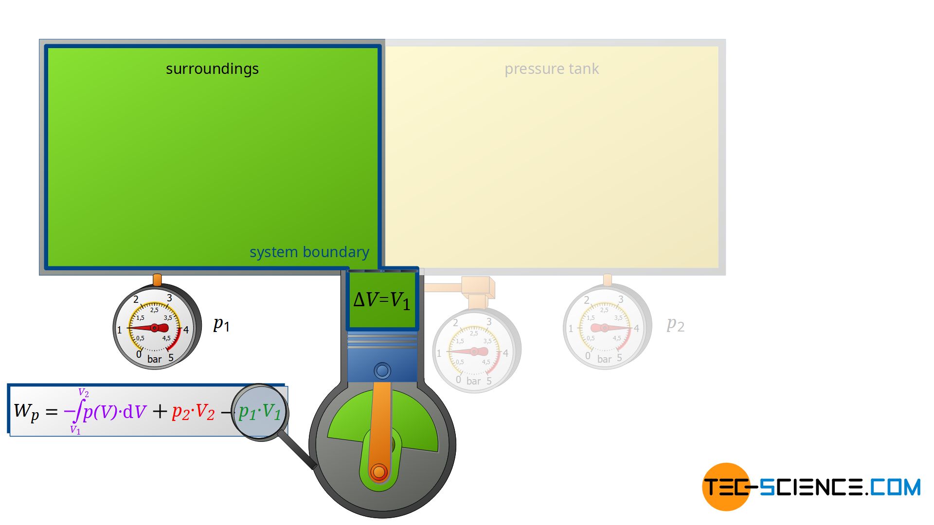
This expansion process of the ambient air can be considered isobaric, since the pressure in the room will not change during this process. The ambient air in the closed room thus expands at constant pressure p1, whereby the volume of the surroundings increases by ΔV = V1. Consequently, the pressure-volume work W1=-p1⋅V1 is performed by the surroundings (this work is to be counted mathematically negative, because the work is done by the ambient air):
\begin{align}
\label{8780}
W_1= -p_1~V_1
\end{align}
Discharge process
Now we consider the discharge process, i.e. when the compressed air is pushed out into the pressure tank. In this case, the tank is again regarded as a closed system. The compressed air already in the container can be thought of as being in a “bubble”. If the (compressed) volume V2 coming from the compressor is now pushed into the pressure tank, the air bubble imagined therein is compressed by this volume. Thus, the volume of the air bubble decreases by the volume V2.
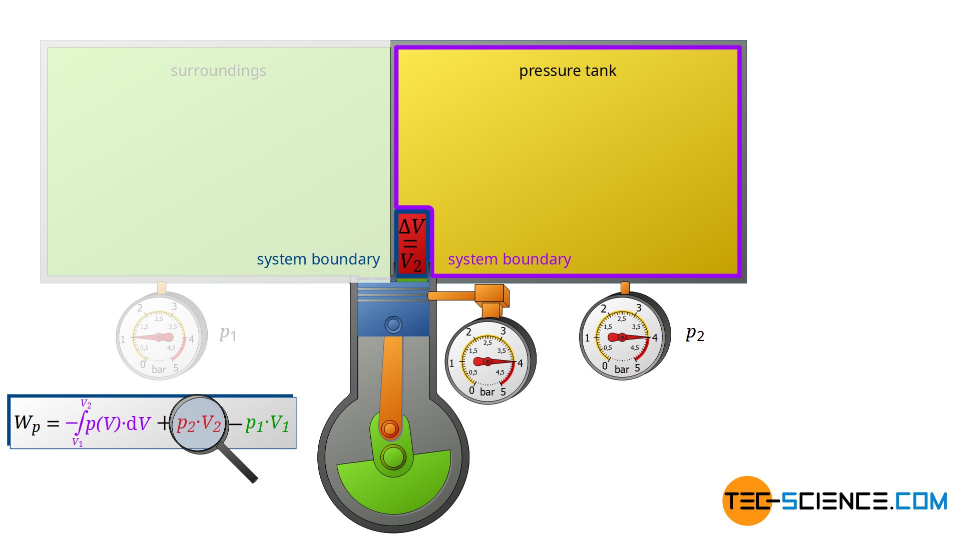
Here again, this compression process can be assumed to be isobaric, if only the pressure tank is large enough. In this case, the small inflow will not significantly change the pressure in the tank. The air already in the tank is thus compressed at constant pressure p2 by the volume ΔV = V2. Thus, the pressure-volume work W2=p2⋅V2 is performed on the air in the pressure tank (this work is to be counted mathematically positive, because work is done on the compressed air in the tank):
\begin{align}
\label{eq:8844}
W_2 = p_2~V_2
\end{align}
Change in energy of the air in the surroundings and in the pressure tank
The energy content of the air in the surroundings therefore changes by the pressure-volume work W1, while the energy content of the air in the pressure tank changes by W2. The cause of these changes is obviously due the open system. The change in energy content is due to the air being pushed in and out and thus corresponds to the flow work Wf of the open system:
\begin{align}
\label{6852}
W_\text{f} = W_2+W_1=p_2~V_2-p_1~V_1
\end{align}
This example shows that the flow work of an open system can be interpreted as pressure-volume work of closed systems which are connected to the open system! The open system (compressor) transfers energy from one closed system (environment) to another closed system (pressure tank), so to speak.
Change in energy of the air inside the compressor
However, the compressor does not only change the energy content of the two closed systems, but also the energy content of the sucked-in air, i.e. the air that is pushed through the open system. For a complete energy balance, therefore, the compression process of the sucked in and compressed air from volume V1 to V2 must also be taken into account.
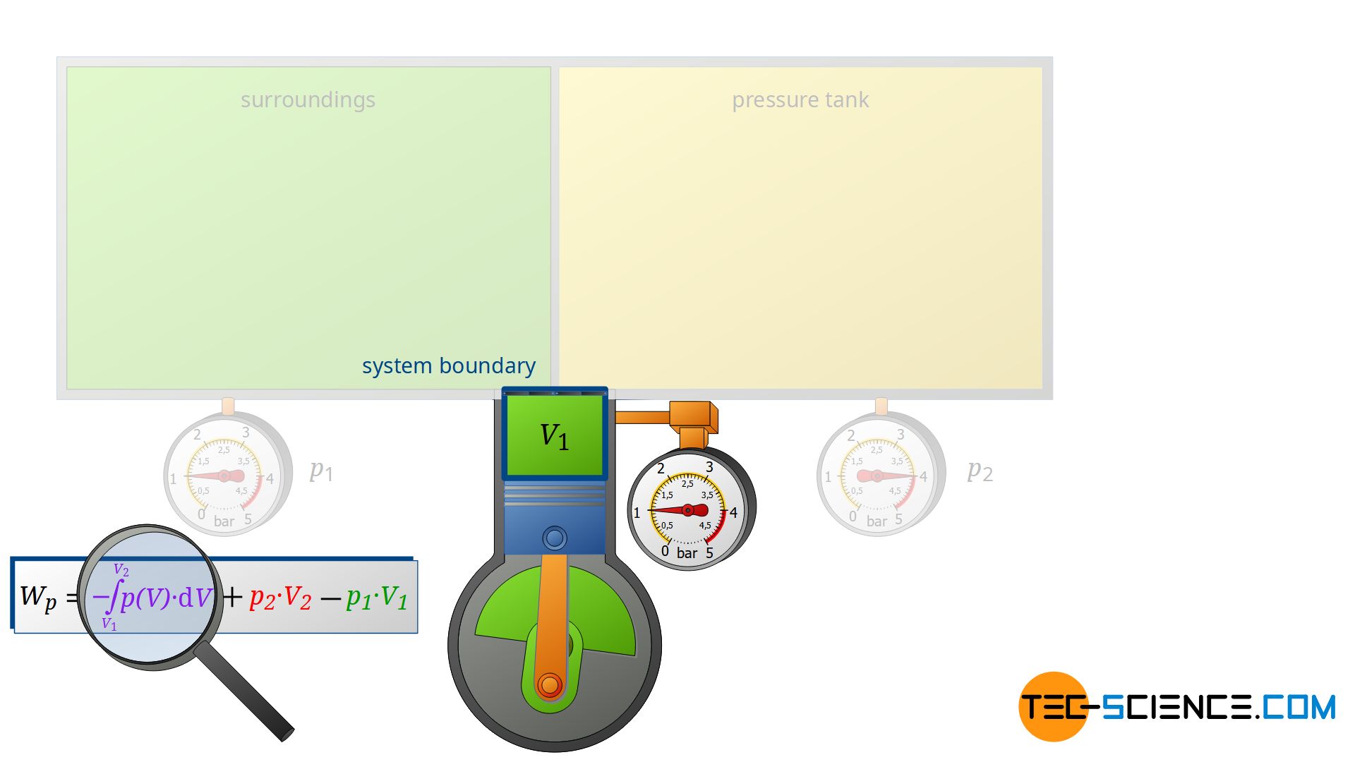
This volume change leads to a third work transfer Wv, which, however, no longer takes place isobarically. Therefore, the integral -∫p(V)⋅dV must be determined to calculate the pressure-volume work in the open system. The sum of all three work transfers is to be done by the compressor and finally corresponds to the total flow process work Wp:
\begin{align}
\label{3568}
W_\text{p} = W_\text{f} + W_2 + W_1=-\int\limits_{V_1}^{V_2}p(V)~\text{d}V + p_2~V_2-p_1~V_1
\end{align}
Note that the compression process of the air from the volume V1 to V2 takes place in the compressor with closed valves. Thus, this work transfer can also be considered as pressure-volume work Wv of a closed system! Therefore, it can be seen that the individual terms in the formula (\ref{4461}) for the calculation of the flow process work can always be traced back to processes of closed systems!
Change in temperature during compression
The isobaric process of the surrounding during the intake process (work transfer W1) is in principle accompanied by a temperature change. The temperature change depends on how much the volume of the ambient air changes. For ideal gases, the law of Gay-Lussac applies. It states that in an isobaric process, the temperature changes to the same extent as the volume changes. However, the increase in volume of the surrounding air due to the retracting piston can be neglected and so can the temperature change. The temperature change of the compressed air in the pressure tank during the isobaric discharge process (work transfer W2) can also be neglected in practice for the same reason.
But nevertheless, in reality, one will notice a significant increase in temperature between the air sucked in and the air pushed out of the compressor! However, this temperature change does not result from the intake or discharge process, but from the compression in the compressor itself (work transfer Wv)! As a rule, not only the pressure but also the temperature of the gas increases during compression. Depending on the type of compressor, temperatures of more than 100 °C can occur. For this reason, compressors are usually cooled.
To determine the temperature change during compression, the first law of thermodynamics for closed systems can be applied. This is because, as already explained, the compression takes place with valves closed and thus in a closed system. Even if the compressor operates without classical valves (e.g. rotary-screw compressor), this process can still always be traced back to a closed system. For example, by simply imagining a bubble around the sucked-in air mass, which represents a closed system.
The first law for a closed system states that the transfer of (pressure-volume) work Wv and heat Q result in a change of the internal energy ΔU of the fluid:
\begin{align}
\label{7560}
\underbrace{-\int\limits_{V_1}^{V_2}p(V)~\text{d}V}_{=W_\text{v}} + Q = \Delta U
\end{align}
For an ideal gas, the change in internal energy ΔU is due only to the temperature change ΔT:
\begin{align}
\label{8373}
\Delta U = c_\text{v}~m~\Delta T
\end{align}
Finally, for an ideal gas, the resulting temperature change ΔT can be determined from the supplied work WV>0 and the dissipated heat Q<0 due to cooling. Or vice versa, the temperature change can then be used to determine the pressure-volume work.
")


