Shaft work is the total work performed in open systems, which is usually transferred by shafts.
Flow process work
In the article on flow process work, the discussion of the work performed in open systems (e.g. in compressors or pumps) was only limited to the flow process work. It was assumed that the open system only has to do work to push the fluid through the system (flow work) and to change the volume of the fluid (pressure-volume work). This work of an open system, called flow process work Wp, can be determined by the following integral:
\begin{align}
\label{7410}
W_\text{p} = \int\limits_{p_1}^{p_2}V(p)~\text{d}p
\end{align}
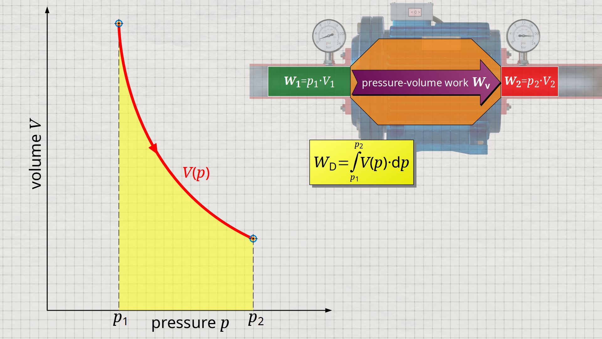
In this integral, V(p) denotes the volume of a fluid element as a function of the pressure when it flows through the open system. Besides the flow process work, however, other energetic processes generally take place in an open system. The following example of a water pump will be used to illustrate this.
Work to accelerate the fluid
We consider a pump where the inlet cross-section is larger than the outlet cross-section. Nevertheless, in the steady-state operation, the same amount of mass flows through the smaller outlet cross-section as through the larger inlet cross-section within a certain time. This fact is due to the conservation of mass (continuity equation), because in steady-state operation, no mass can accumulate or be annihilated in the pump. Thus, the same amount of water will enter the pump through the inlet cross-section as exits at the outlet cross-section at the same moment.
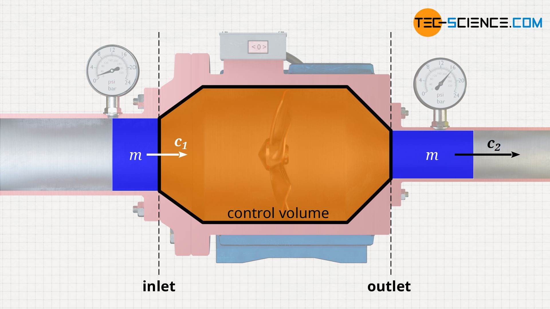
However, since the outlet cross-section is smaller, the water mass there must flow through at a higher velocity. Only in this way can the same mass of water flow through as at the inlet in the same time. This phenomenon is also familiar from everyday experience: if you squeeze the front end of an open garden hose and thus reduce the cross-section, the water flows out at a higher speed.
Accordingly, a fluid element of mass m must be accelerated from the inflow velocity c1 to the outflow velocity c2 when flowing through the pump. Thus, in addition to the flow process work, the pump also has to do work Wa on the fluid to accelerate it:
\begin{align}
\label{6723}
\boxed{W_\text{a} = \tfrac{1}{2}~m~\Delta c^2} ~~~\text{where}~~~ \Delta c^2 = c_2^2 – c_1^2
\end{align}
Note: With identical inlet and outlet cross sections, no work needs to be done to accelerate the fluid for incompressible fluids such as liquids, since the velocities do not change. For compressible fluids such as gases, however, the flow velocity will change even with identical inlet and outlet cross sections, since the gas is pushed out with a significantly different volume, which in turn requires different velocities in order to keep the mass flow constant.
Gravitational work to lift the fluid
In the previous considerations, the inlet of the pump was at the same height as the outlet. However, this does not necessarily have to be the case! In general, the inlet and outlet are at different heights. In centrifugal pumps, the pump outlet is usually higher than the pump inlet. To overcome this height difference, the pump must do work on the fluid to lift it.
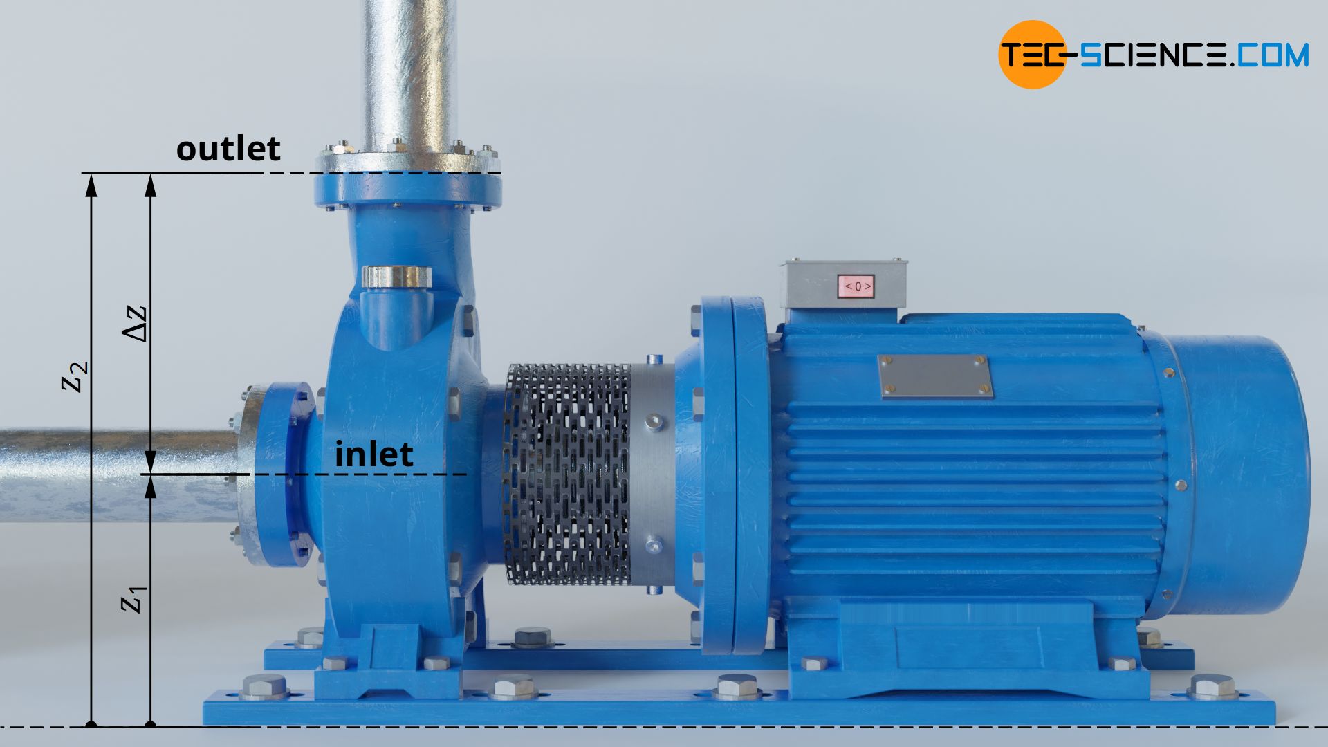
The water must now no longer simply be pushed through the pump against the acting pressure difference between inlet and outlet, but the fluid mass m flowing through must be lifted against gravity by the height Δz=z2-z1. This requires the gravitational work Wg:
\begin{align}
\label{2735}
\boxed{W_\text{g} = m~g~\Delta z} ~~~\text{where}~~~ \Delta z = z_2-z_1
\end{align}
Shaft work
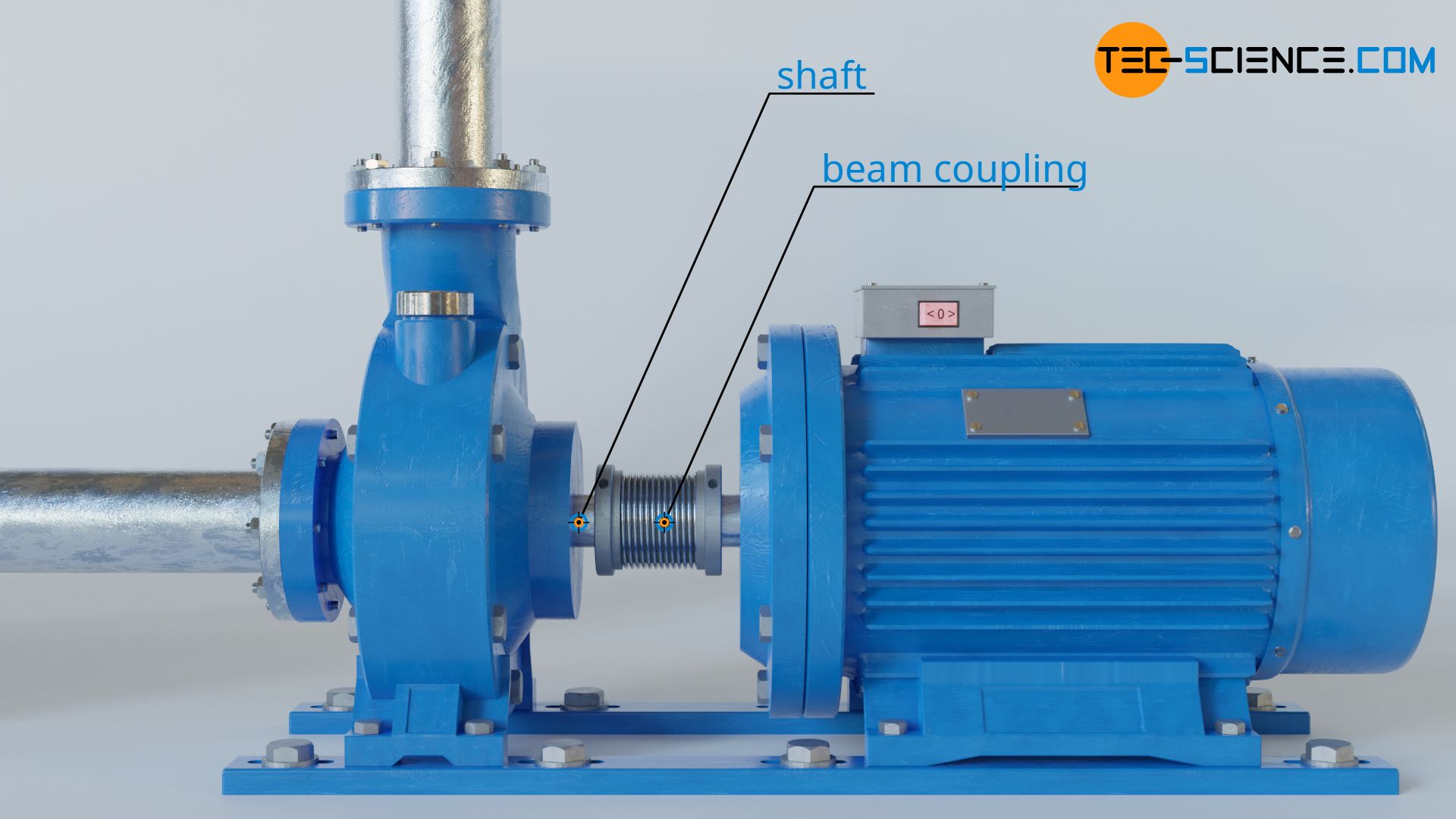
The flow of the fluid through the pump will not be frictionless in reality due to the viscosity of the fluid. And also the friction in the bearings must be taken into account. As a result, the pump must also do work to compensate for the friction, which is commonly referred to as dissipation work Wdiss.
All the above mentioned energetic processes, i.e. the sum of
- flow process work Wp (= flow work + volume-pressure work),
- acceleration work Wa,
- lifting work Wg and
- dissipation work Wdiss (frictional work),
must be done by the pump. An open system need not always be a pump, which is why this type of work is commonly referred to as shaft work Ws. Shaft work is the total work that an open system must do on the fluid (for pumps) or that is done by the fluid (for turbines). Since this work is usually transferred by shafts, it is referred to as shaft work.
\begin{align}
\label{8918}
&W_\text{s} = W_\text{p} +W_\text{a} +W_\text{g} +W_\text{diss} \\[5px]
\label{e8761}
&\boxed{W_\text{s} = \int\limits_{p_1}^{p_2}V(p)~\text{d}p + \tfrac{1}{2}~m~\Delta c^2 + m~g~\Delta z + W_\text{diss}} ~~~~~\text{shaft work} \\[5px]
\end{align}
or as specific shaft work ws (shaft work per unit mass):
\begin{align}
\label{9228}
\boxed{w_\text{s} = \int\limits_{p_1}^{p_2}v(p)~\text{d}p + \tfrac{1}{2}~\Delta c^2 + g~\Delta z + w_\text{diss}} ~~~~~\text{specific shaft work}
\end{align}
Finally, the shaft power Ps can be calculated from the specific shaft work ws multiplied by the mass flow rate m’ which is transported through the open system (for the derivation of this formula see article Flow work in open systems):
\begin{align}
\label{4794}
\boxed{P_\text{s} = w_\text{s}~\dot{m}}
\end{align}
Note: So far, only pumps or compressors have been considered as open systems. These systems are transferring shaft work to the fluid, i.e. work is done on the fluid by the open system. However, such thermodynamic processes can also take place in reverse, i.e. the fluid does work on the open systems and transfers shaft work to the surroundings. This is the case, for example, in water turbines or steam turbines. These transfer mechanical work to the surroundings by the turbine shaft. The equations considered so far can in principle be applied to any open system.
Choice of system boundaries
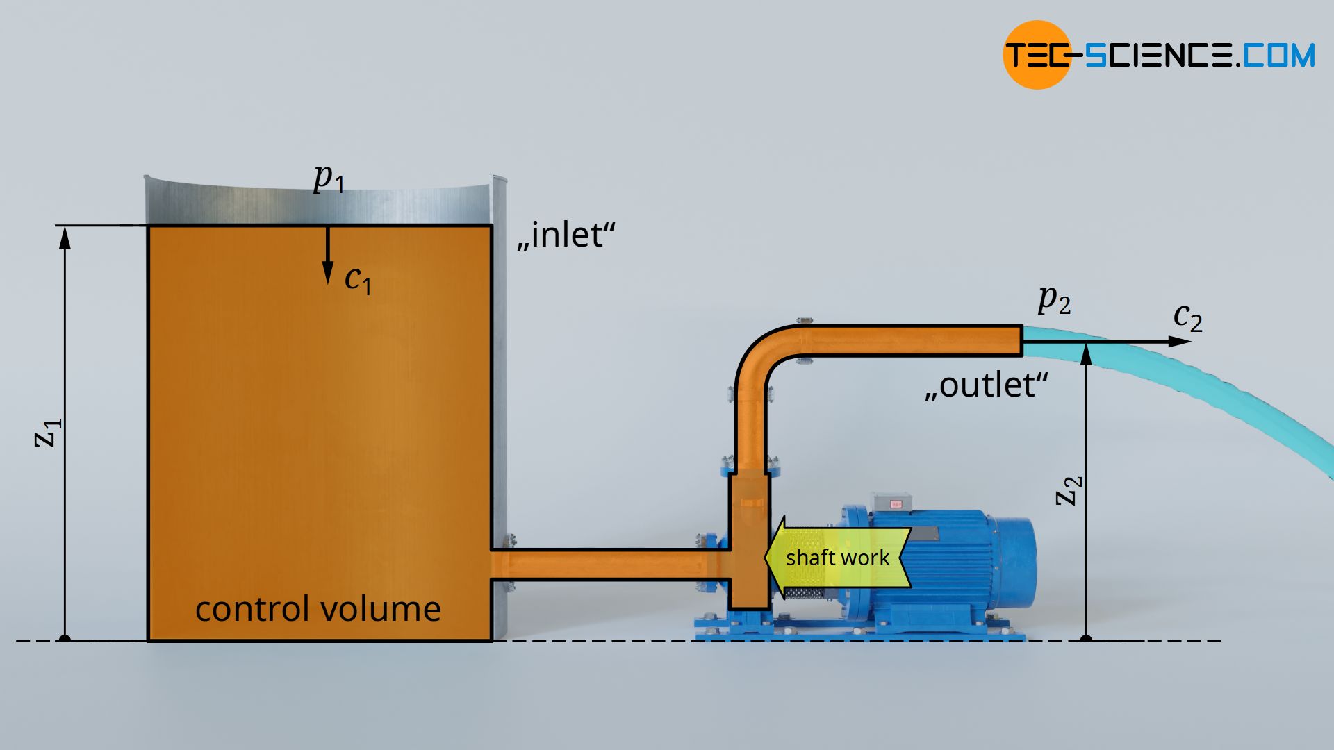
Note that the flow velocities c heights z and pressures p given in the upper equations are defined at the boundaries of the open systems, i.e. when the fluid flows into or out of the open system (also called control volume).
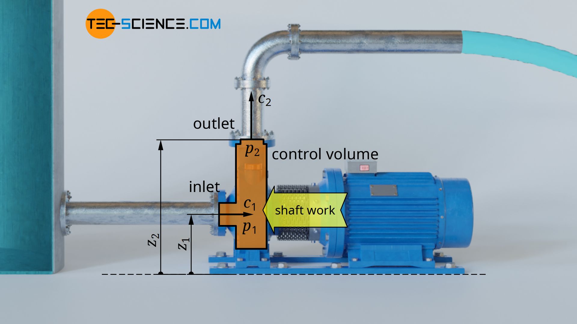
Depending on the choice of the system boundary, this can result in completely different values for the respective quantities. It would also be possible to include the entire piping system and the water tank in the consideration as part of the open system. The system boundaries would then be at the surface of the water tank and at the end of the pipe. This approach would be based on completely different pressures, volumes, flow velocities and heights at the boundaries!

")

