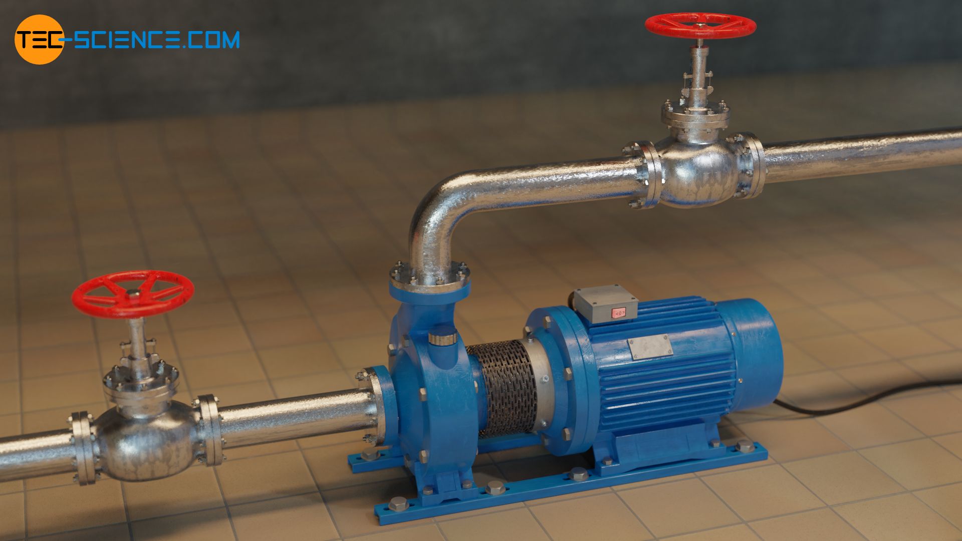
Centrifugal pumps have a wide range of applications where the pressure increase is caused by centrifugal forces.
Radial, axial and mixed flow pumps
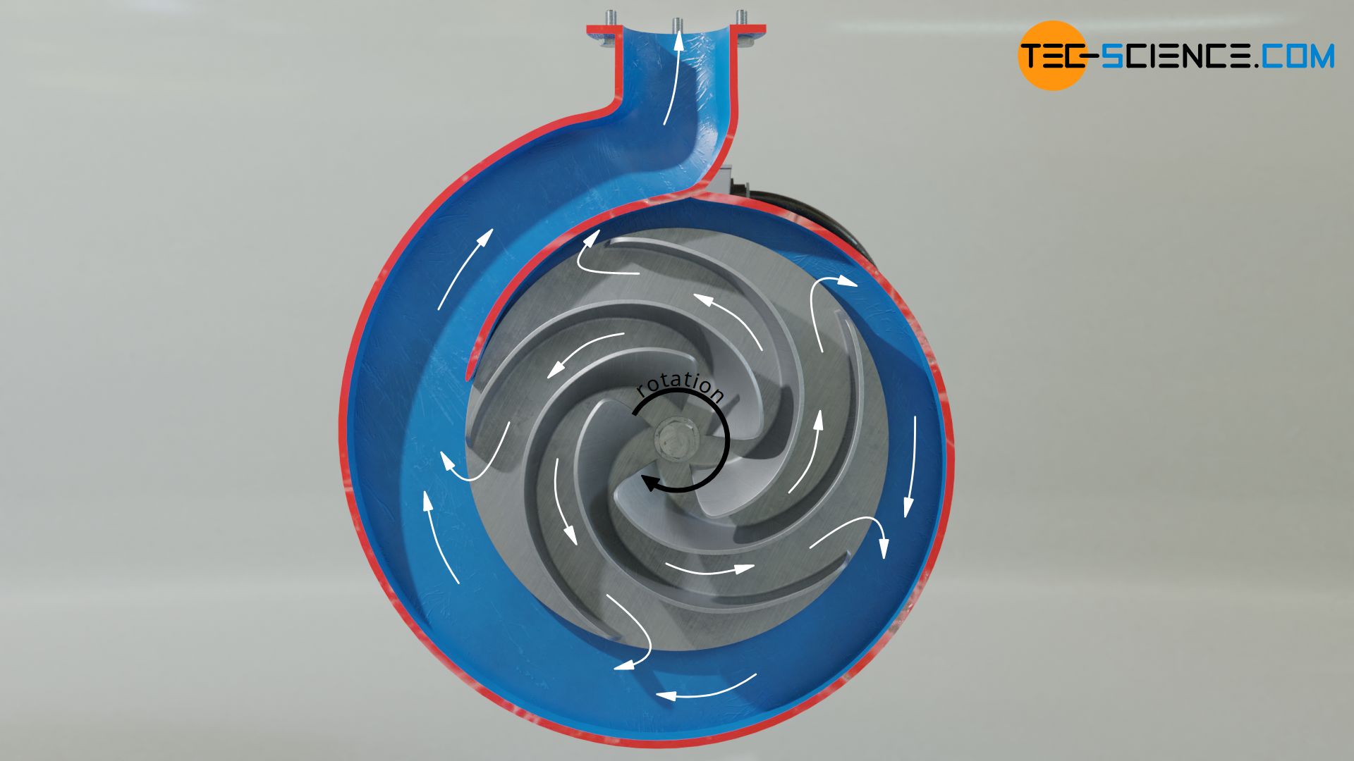
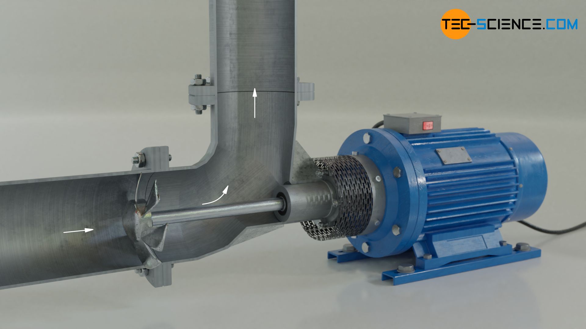
Centrifugal pumps are turbomachines that pump liquids by means of centrifugal force generated by rotating impellers. Axially to the impeller, the liquid to be pumped enters the suction port of the pump on the suction side. The impeller rotating in the pump accelerates the liquid under the effect of centrifugal force.
The increase in speed raises the dynamic pressure in the fluid. When leaving the impeller, the liquid is slowed down again at the discharge port due to the accumulated liquid. Thus, the dynamic pressure of the liquid is converted into static pressure (more information about the relationship between dynamic and static pressure can be found in the article Venturi Effect). As a result, the static pressure at the discharge port increases very much. This high pressure enables the liquid to overcome a certain geodetic head.

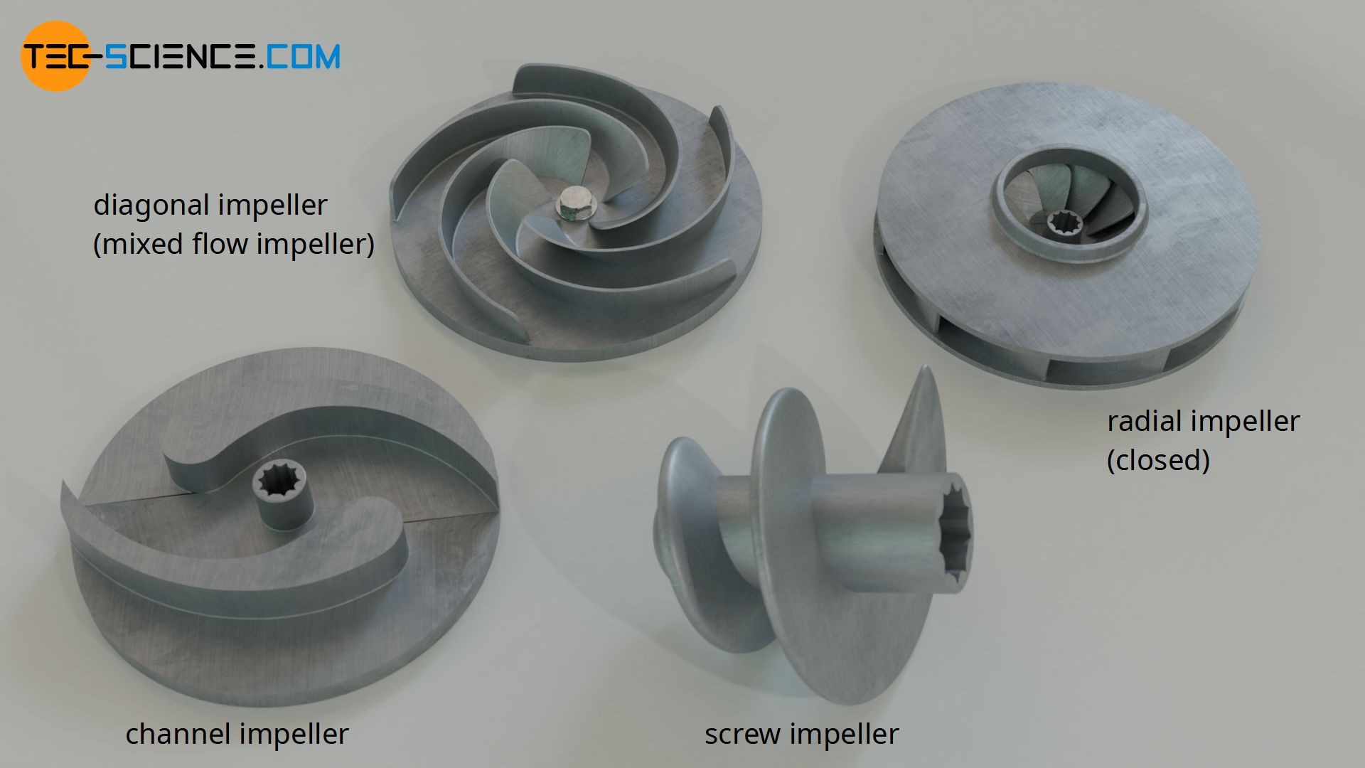
Depending on the design of the pump or impeller, the liquid leaves the impeller in radial or axial direction. Pumps that generate a radial flow are also called radial flow pumps. The impellers of radial pumps are designed either as a closed impeller with a cover plate or as an open impeller (the latter is shown in the figures).
If the liquid leaves the impeller in axial direction, this design is also called axial flow pump. In this case, the impeller acts like a propeller of a ship, except that in this case the propeller is stationary and thus creates a flow inside the pipe. Therefore axial pumps are also called propeller pumps. They are often used as circulation pumps in chemical plants. There are also centrifugal pumps where the liquid does not leave the impeller exactly axially or radially. These pumps are then called diagonal flow pumps or mixed flow pumps.
Centrifugal pumps are turbomachines that deliver liquids by means of centrifugal forces! Depending on the flow generated in relation to the impeller, they are called radial flow pumps, axial flow pumps or mixed flow pumps!
In contrast to axial flow pumps, radial flow pumps can provide higher pressure heads, but they usually produce a relatively low flow rate. To achieve high flow rates, several radial flow pumps may have to be connected in parallel. Axial flow pumps offer high volumetric flow rates, but only relatively low pressure heads (approx. 15 m). In order to achieve large pressure heads with axial flow pumps, several pumps may have to be connected in series. A compromise between the advantages and disadvantages of both pump types is offered by mixed flow pumps.
Radial flow pumps provide high pressure heads at low flow rates, while axial flow pumps provide high flow rates at low pressure heads. Mixed flow pumps offer a compromise of both designs.
Radial impellers with one to a maximum of three vanes are used for pumping heavily contaminated liquids or liquids containing solids. The small number of vanes increases the flow cross-section and thus improves the flow through the impeller. Such impellers are also called channel impellers. In the case of propeller pumps, a screw design of the impeller is used when it comes to pumping liquids containing solids.
Cavitation
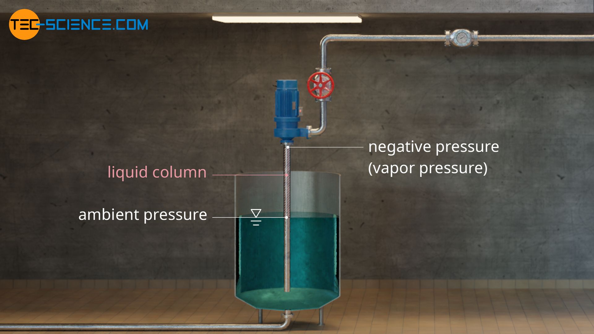
The pump sucks in the fluid due to the negative pressure generated at the suction port. More precisely: the higher ambient pressure outside the suction pipe pushes the fluid into the pump in the direction of the negative pressure (principle of drinking with a straw). Since the ambient pressure is 1 bar and a pump can create a vacuum at most, the pressure with which the fluid can be pressed into the pump is limited to a maximum of 1 bar. This allows only a limited geodetic suction head to be achieved. In the case of pumping water, the maximum suction lift when a perfect vacuum is created is theoretically 10 meters.
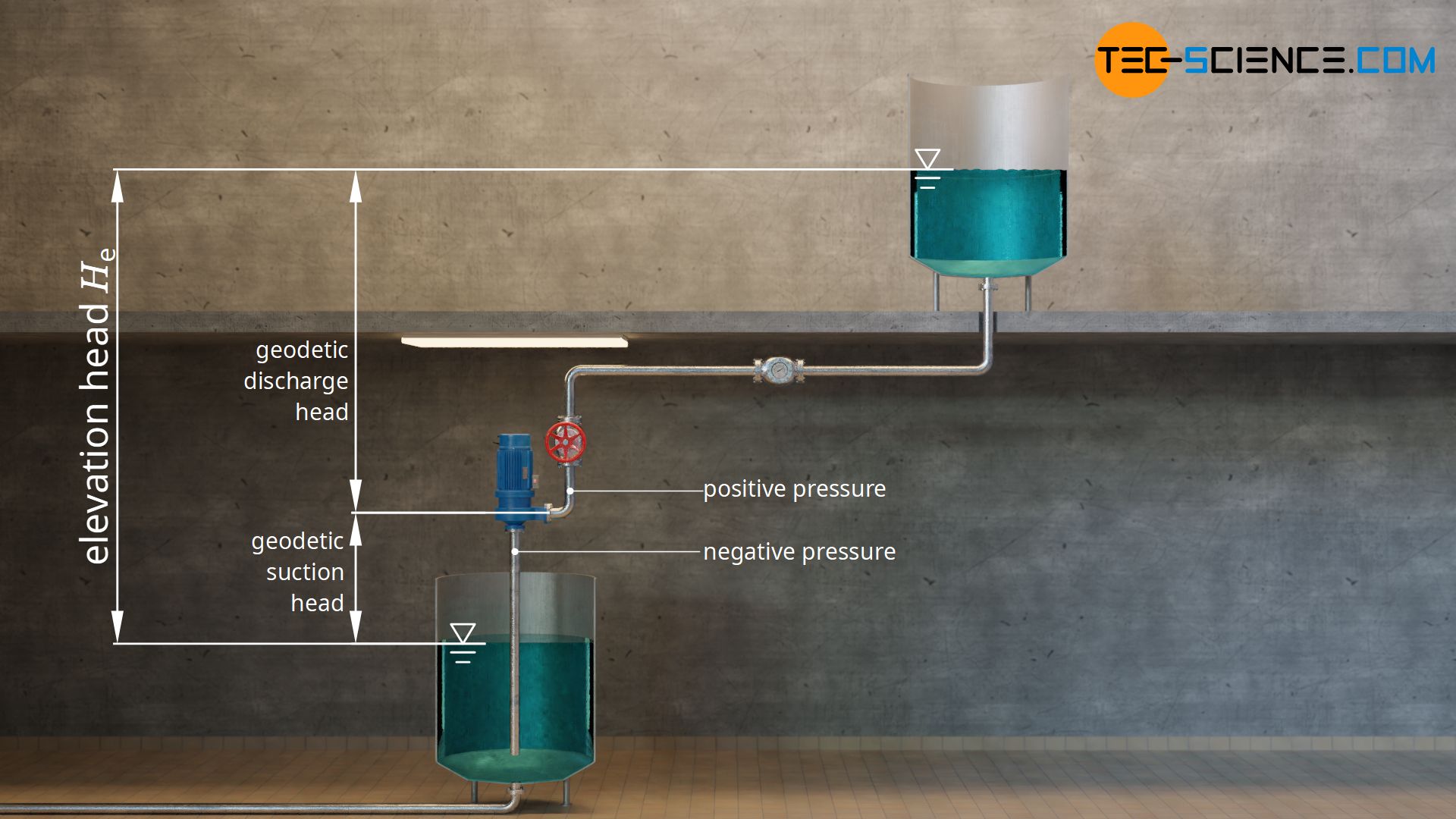
However, the suction head of a centrifugal pump is not only limited by the ambient pressure, but also by cavitation. Cavitation is the formation of vapor bubbles when the static pressure in a liquid falls below the vapor pressure. The vapor pressure of water at a temperature of 20 °C is 23 mbar. If the static pressure in water falls below this value, the water starts to evaporate locally even at this low temperature and small gas bubbles are formed (analogous to the rising vapor bubbles when water is boiling).
If the pressure in the pump subsequently rises again, the gas bubbles become unstable and implode. Since this is a gas-filled bubble, the particle density is relatively low. Thus, the bubble collapses with almost no resistance. The surrounding liquid is accelerated so strongly in the collapsing bubble that the resulting micro jets generate local pressures of several thousand atmospheres! If such micro jets hit the vanes of the impeller, this leads to damage over time. The occurrence of cavitation is often noticed by loud noises or vibrations of the pump.
Cavitation is the formation of vapor bubbles and their subsequent implosion, whereby the resulting micro-jets destroy the surfaces of components!
Areas in which the static pressure is relatively low are particularly susceptible to the formation of vapor bubbles. This is the case at the pump inlet for two reasons. On the one hand, the pump must have a negative pressure there anyway, so that the liquid can be delivered into the pump at all. In addition, according to the Venturi effect, the static pressure decreases when the flow velocity increases. Especially at the inlet to the impeller, the flow velocity is particularly high due to the reduced inlet cross section, and the static pressure is thus lowest. If the pressure drops below the vapor pressure there, gas bubbles are formed which finally implode due to the pressure increase in the pump.
NPSH value
The risk of cavitation is obviously particularly high when the pump has to generate a strong negative pressure to deliver the fluid. From the perspective of the piping system, this is the case with large geodetic suction heads and with large head losses of the suction pipe (caused by friction). From the perspective of the pump, the risk of cavitation is high with high flow rates, since this in turn means high flow velocities and thus leads to a strong drop in static pressure.
NPSH value of the piping system (NPSHA)
For cavitation free operation of centrifugal pumps, it must therefore be ensured that the total pressure at the inlet of the pump (center of the suction port as reference level) does not fall below the vapor pressure of the liquid to be pumped. The existing difference Δp between the total pressure at the inlet pin,tot and the vapor pressure of the liquid pvap is determined with the following equation, where the total pressure can be written as the sum of static pressure pin and dynamic pressure ϱ/2⋅vin2 (vin denotes the mean flow velocity at the inlet to the impeller):
\begin{align}
&\Delta p = p_\text{in,tot} – p_\text{vap} \\[5px]
\label{dp}
&\Delta p = \left(p_\text{in}+\frac{\rho}{2}v_\text{in}^2 \right) – p_\text{vap} \\[5px]
\end{align}
What is the meaning of this equation? Without taking losses into account, the total pressure at the inlet (term in the round brackets) corresponds to the total pressure with which the medium is pressed into the open end of the suction pipe due to the conservation of energy. This pressure is counteracted at the other end of the suction pipe (inlet to the impeller) by the vapor pressure of the liquid as minimum available pressure. Thus, the pressure difference Δp can be interpreted as net positive suction pressure with which the liquid could be sucked in at maximum without falling below the vapor pressure.
This net positive suction pressure can also be converted into an equivalent height (head) of a liquid column that could be raised with this suction pressure. This is called the Net Positive Suction Head (NPSH). To determine the available NPSH value of the piping system (index A for available), equation (\ref{dp}) is divided by the term ϱ⋅g:
\begin{align}
&\underbrace{\frac{\Delta p}{\rho g}}_{\text{NPSH}_\text{A}} = \left(\frac{p_\text{in}}{\rho g}+\frac{v_\text{in}^2}{2g}\right) – \frac{p_\text{vap}}{\rho g} \\[5px]
\label{a}
&\underline{\text{NPSH}_\text{A} = \left(\frac{p_\text{in}}{\rho g}+\frac{v_\text{in}^2}{2g} \right) – \frac{p_\text{vap}}{\rho g}} \\[5px]
\end{align}
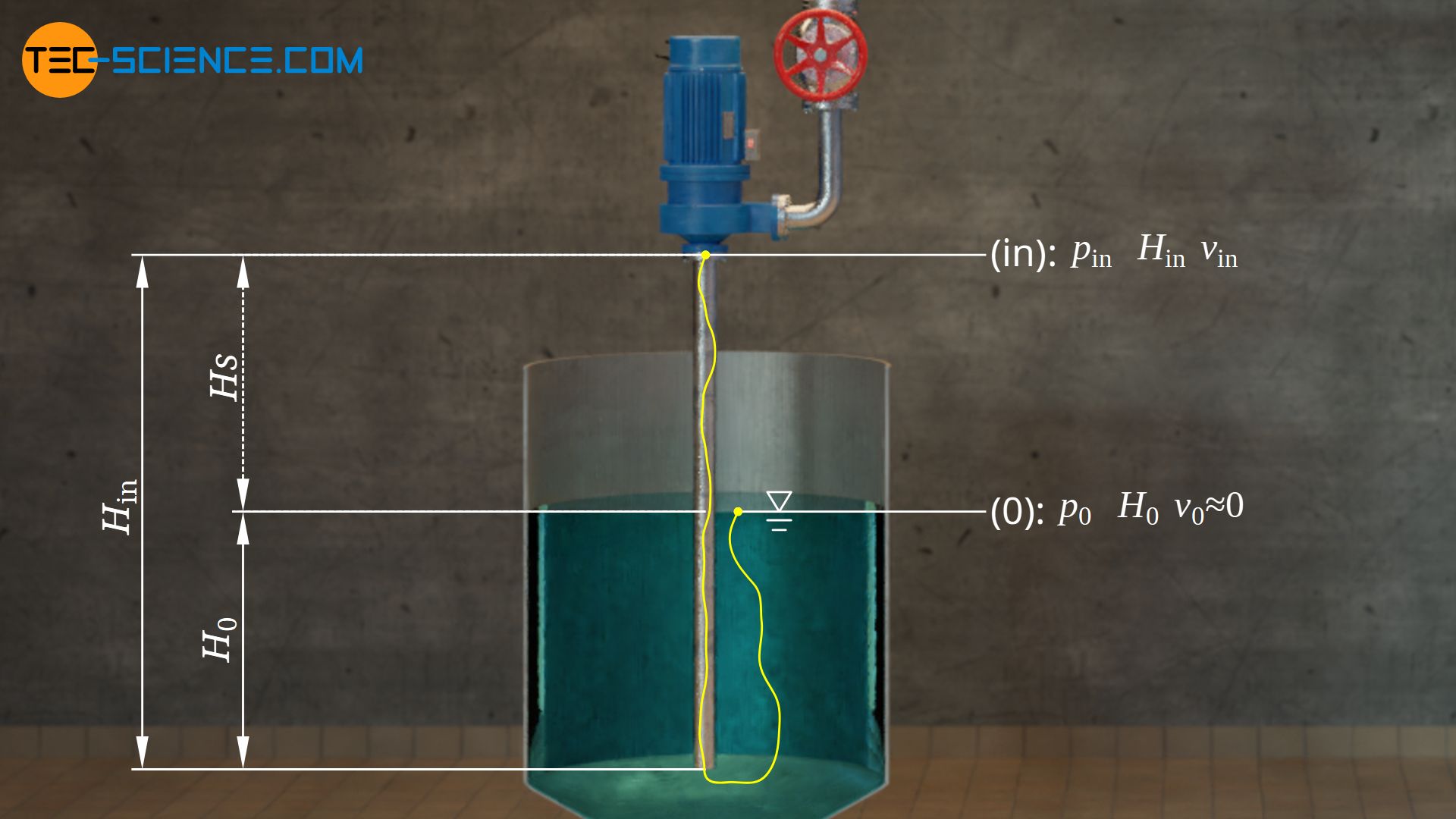
Using the extended Bernoulli equation, a relationship can be established between the state of the liquid at the tank (0), where the liquid is sucked in, and the state at the inlet to the impeller (in). Pressure losses Δploss in the suction pipe are also taken into account, whereby kinetic energies are neglected due to the usually low rate of descent of the liquid level in the tank (v0≈0).
\begin{align}
\require{cancel}
& p_0 + \frac{1}{2} \rho \cancel{v_0^2} +\rho g H_0= p_\text{in} + \frac{1}{2} \rho v_\text{in}^2 + \rho g H_\text{in} + \Delta p_\text{loss}\\[5px]
& p_0 + \rho g H_0= p_\text{in} + \frac{1}{2} \rho v_\text{in}^2 + \rho g H_\text{in} + \Delta p_\text{loss} \\[5px]
& \frac{p_0}{\rho g} + H_0= \frac{p_\text{in}}{\rho g} + \frac{v_\text{in}^2}{2g} + H_\text{in} + \underbrace{\frac{\Delta p_\text{loss}}{\rho g}}_{\text{head loss }H_\text{loss}} \\[5px]
& \frac{p_\text{in}}{\rho g} + \frac{v_\text{in}^2}{2g} = \frac{p_0}{\rho g} – \underbrace{(H_\text{in}~ -~ H_0)}_{\text{geodetic suction head }H_\text{s}} – H_\text{loss} \\[5px]
\label{pe}
& \underline{\frac{p_\text{in}}{\rho g} + \frac{v_\text{in}^2}{2g} = \frac{p_0}{\rho g} – H_\text{s} – H_\text{loss}} \\[5px]
\end{align}
The term in the round bracket in equation (\ref{a}) can now be replaced by equation (\ref{pe}):
\begin{align}
&\text{NPSH}_\text{A} = \left(\frac{p_0}{\rho g} – H_\text{s} – H_\text{loss} \right) – \frac{p_\text{vap}}{\rho g} \\[5px]
&\boxed{\text{NPSH}_\text{A} = \frac{p_0-p_\text{vap}}{\rho g} – H_\text{s} – H_\text{loss}} \\[5px]
\end{align}
In this equation, Hloss denotes the head loss due to friction and flow losses inside the suction pipe. The geodetic suction head Hs corresponds to the difference in height between the liquid level in the tank and the inlet to the impeller. For a so-called suction operation, i.e. when the tank is lower than the pump inlet, a positive value must be used for the suction head. If the tank is higher than the pump inlet, this is called pressure operation and the value for the “suction head” has a negative sign.
NPSH value of the pump (NPSHR)
The NPSHA value corresponds to the available pressure head due to the characteristics of the piping system. For cavitation free operation, the pump with its provided pressure head must not exceed the NPSHA value of the system. It is therefore absolutely necessary that the pump generates a lower NPSH value than is available from the perspective of the system. The NPSH value of the pump is therefore referred to as the NPSHR value (index R for Required).
The NPSHR values of centrifugal pumps are specified by the manufacturers in their data sheets. The NPSHR value is strongly dependent on the rotational speed of the impeller and the delivered flow rate. For safety reasons the NPSHA value of the system should be about 0.5 m higher than the NPSHR value of the pump:
\begin{align}
&\boxed{\text{NPSH}_\text{A} \geq \text{NPSH}_\text{R} + 0,5 \text{ m}} ~~~\text{cavitation free operation} \\[5px]
\end{align}
Measures to prevent cavitation
If cavitation occurs during operation of a centrifugal pump, appropriate countermeasures must be taken. Reducing the flow velocity is crucial to prevent the pressure from dropping too much.
From the perspective of the pump, this can be achieved, for example, by reducing the rotational speed of the impeller. However, the flow rate decreases with this measure. If such a reduction of the flow rate is not wanted, a larger pump must be used, which delivers the same flow rate at lower speeds.
An excessive drop in pressure can also be prevented by the use of a so-called inducer. An inducer is an axial impeller which is connected upstream of the actual pump impeller and is mounted on the same shaft. Inducers increase the static pressure of the fluid before it enters the actual impeller (or before the first stage of several impellers) and thus reduce the risk of the pressure falling below the vapor pressure (reduction of the NPSHR value of the pump).
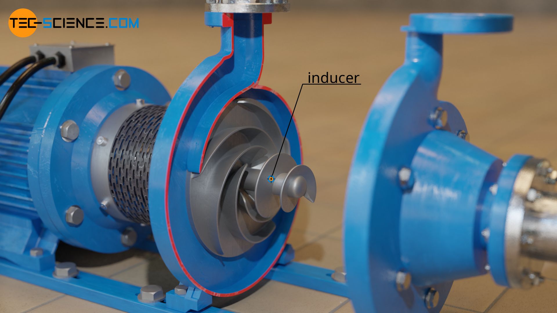
Centrifugal pumps with inducers are being operated in the partial load range, since cavitation would occur in the inducers under full load. Therefore, pumps with inducers cannot cover the entire load range compared to pumps without inducers. Due to the additional impellers, the energy conversion efficiencies are also lower.
Measures to reduce/avoid cavitation can also be taken from the perspective of the piping system. An increase in the cross-section of the suction pipe (at constant flow rate) also causes a reduction in the flow velocity. In this context, the suction pipe should also be checked for blockages.
Another possibility to avoid cavitation is to keep the geodetic suction head as low as possible. For this purpose either the suction tank must be placed higher or the pump lower. It may also be necessary to consider a changeover from suction operation to pressure operation.
Start-up and shut-down procedure of centrifugal pumps
Centrifugal pumps should not be just switched on and off, as this can cause damage to the pump. Therefore a certain procedure must be followed. First of all, the pump should not be switched on when no fluid is inside the pump and the pump must not run dry during operation. On the one hand, centrifugal pumps usually cannot generate a suction effect when running dry and thus cannot pump any fluid (exception: self priming pumps like side-channel pumps). On the other hand, the flowing liquid also serves to cool the pump. If this cooling is missing, the pump overheats very quickly. In addition, the liquid pressure exerts a certain centering effect on the rotating components within the pump and thus prevents direct contact with adjacent housings. For the reasons mentioned above, centrifugal pumps often have a dry running protection which immediately switches off the pump if there is no liquid.
Before starting the pump, it must therefore be filled with liquid (priming). When priming the pump, it must not be emptied again through the suction pipe. For this reason, a check valve or a foot valve (non-return valve) is usually installed in the suction pipe, which automatically prevents a backflow. A simple block valve or gate valve can also be installed, which must then first be closed manually.
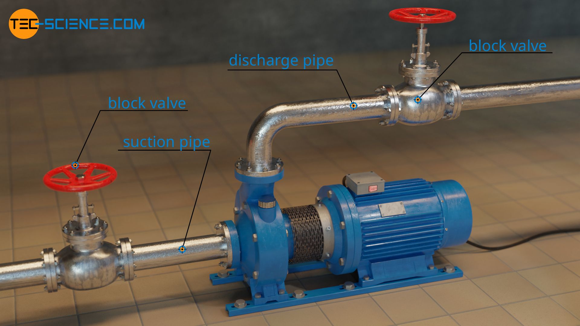
If the pump were switched on directly after filling and with the valve open, the pump would immediately deliver a high flow rate. To set the shaft of the electric motor in rotation and at the same time deliver a high flow rate would require a very high electrical power of the motor. This can lead to overheating. To prevent this from happening, the flow rate must be throttled when the pump is started.
However, the flow rate is not throttled by a block valve in the suction pipe, since a constriction in the suction pipe would increase the flow velocity and thus pose the risk of cavitation. For this reason there is another block valve in the discharge pipe, which is initially closed when the pump is switched on and is only gradually opened so that the flow rate slowly increases to its maximum.
In summary, centrifugal pumps are started up by the following procedure:
- Close the valve in the suction pipe (prevents running dry of the pump)
- Fill the pump with fluid (achieving a suction effect and protection against overheating)
- Close the valve in the discharge pipe
- Open the valve in the suction pipe completely (avoiding cavitation)
- Switch on the pump motor
- Slowly open the valve in the discharge pipe (preventing the motor from overheating)
When the pump is to be shut down, a certain procedure must also be followed. First the valve in the discharge pipe is slowly closed again. A too fast closing should be avoided, because otherwise the liquid behind the valve is tempted to continue flowing due to its inertia and thus a very high negative pressure is created. The negative pressure then pulls the liquid back again and hits the valve with full force. This can destroy both the valve and the pipe.
After closing the valve in the discharge pipe, the pump can now be switched off. The block valve in the suction pipe should then be closed again to prevent the pump from running empty. With non-return valves this happens automatically.
In summary, centrifugal pumps are shut down by the following procedure:
- Slowly close the valve in the discharge pipe (preventing pressure surges)
- Switch off the pump motor
- Close the block valve in the suction pipe (prevents running dry of the pump)
")


")
")
