Flow process work is the work done by an open system to transfer a fluid through the system boundaries (flow work) and change the volume (pressure-volume work).
Energetic processes at the boundaries of an open system (flow work)
The article on flow work used the example of a water pump to explain that flow work is the work that must be done to push a fluid through an open system. This is due to the pressure difference between entering the system (e.g. pump inlet with low pressure) and leaving the system (e.g. pump outlet with high pressure). In pumps, the fluid is pushed in by the surroundings with lower energy W1 and pushed out by the pump with higher energy W2.
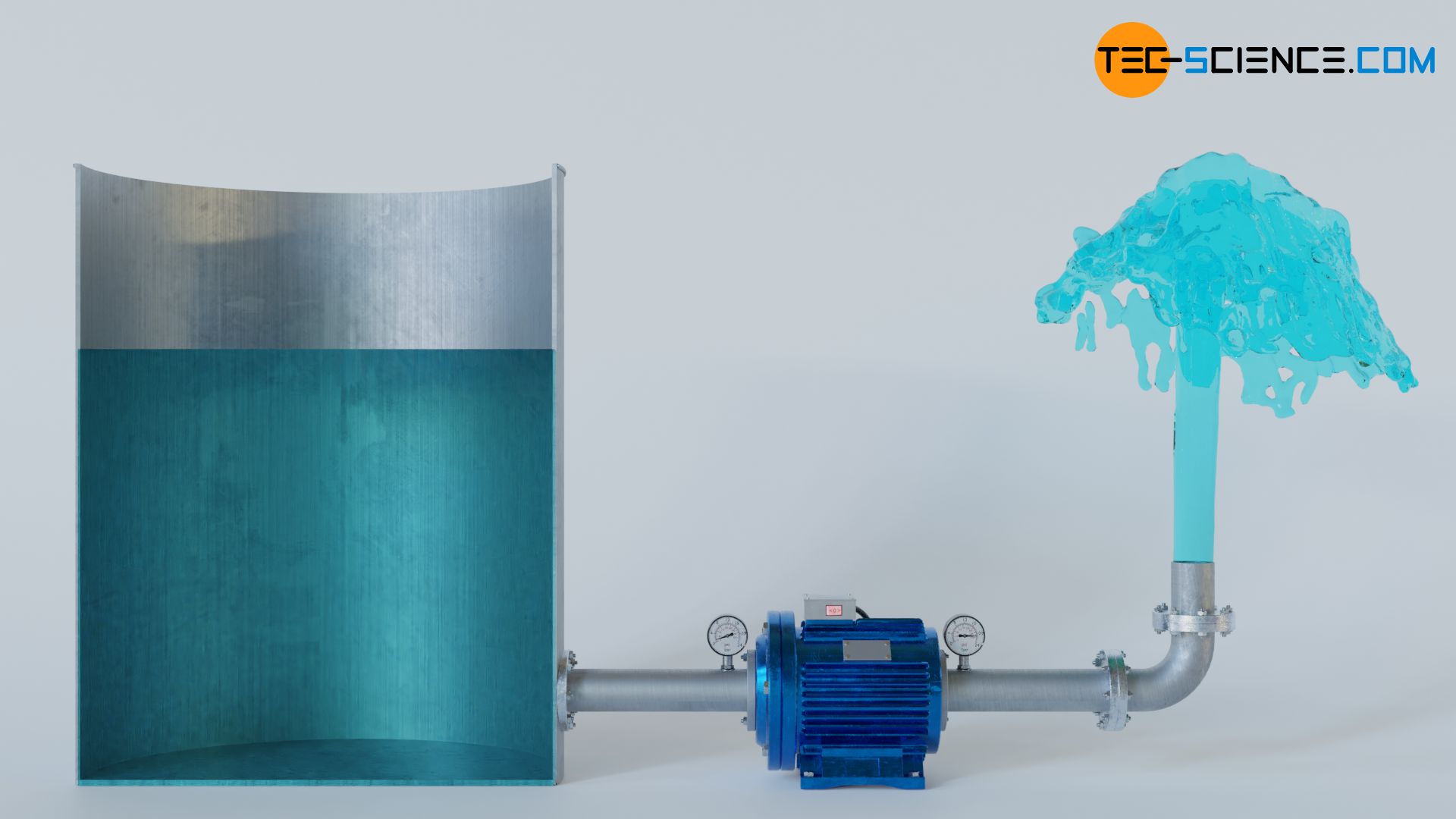
The energy with which the fluid ist pushed in or out result from the product of the fluid volume V, which is transferred across the system boundary, and the pressure p acting there. The difference between these energies is the work done by the system, e.g. the work of the pump, and is generally called flow work Wf:
\begin{align}
&W_\text{f} = W_2 – W_1 \\[5px]
&W_\text{f} = p_2 \cdot V_2 – p_1 \cdot V_1 \\[5px]
\end{align}
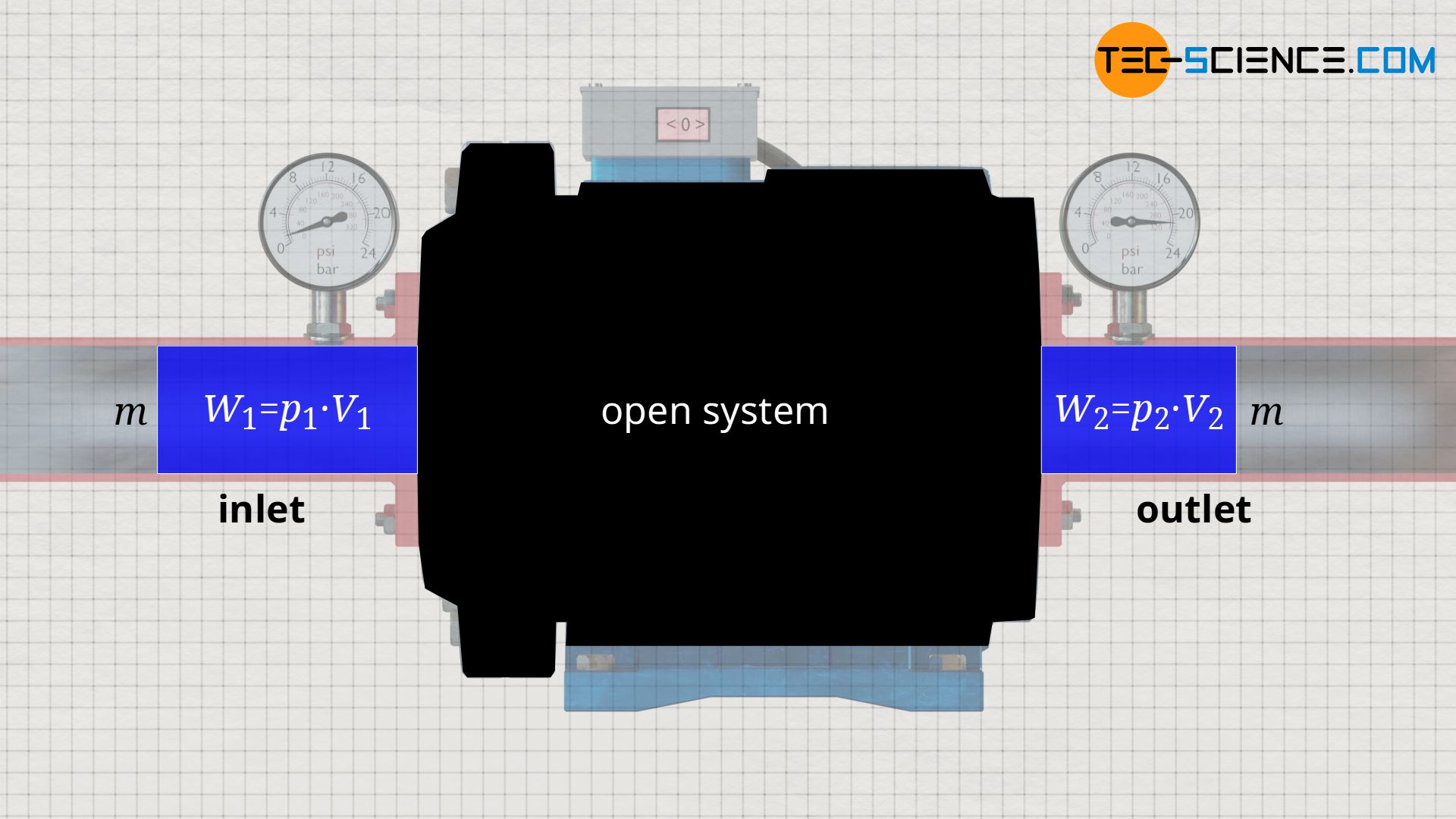
The knowledge gained from the example of the water pump can be applied to any open system, because in every open system, a certain fluid mass m is pushed into the system with volume V1 and pressure p1, and is pushed out of the system again with a changed volume V2 and a changed pressure p2.
Energetic processes inside the open system (pressure-volume work)
In an open system, the flow work is due solely to the fact that the fluid must be displaced against the pressure difference between system inlet and system outlet. Obviously, only the energetic processes at the system boundaries are relevant. However, this consideration does not take into account the internal processes inside the open system itself when the fluid flows through the system. So far, the open system has only been considered as a “black box”. Therefore, in the following we will take a closer look at the energetic processes inside an open system.
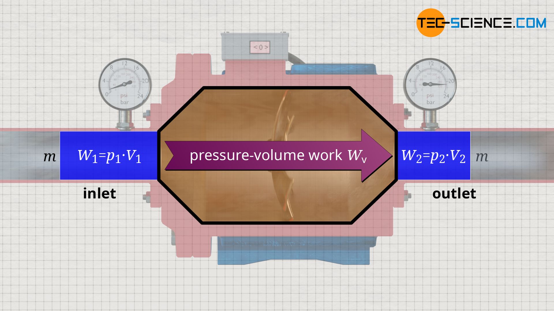
For an overall energy balance, not only the energetic processes at the system boundary must be considered (flow work), but also the processes in the system itself must be examined more closely. For example, a change in pressure occurring inside an open system generally also causes a change in volume of the fluid. Such an internal process of volume change has not been discussed so far. This volume change did not have to be taken into account in the example of the water pump, since water is an (almost) incompressible fluid. With such incompressible fluids, there is no volume change.
In the case of compressible fluids such as gases, however, a pressure-induced change in volume requires pressure-volume work, because a gas does not change its volume by itself, but only by performing work! Thus, in addition to the flow work which is performed at the boundaries of the open system, the pressure-volume work which is performed inside the open system must also be taken into account, especially in the case of gases.
Control volume
The processes taking place in an open system can be imagined more clearly if the entering fluid is regarded as a closed system. One thinks of a “bubble” around a considered fluid element with mass m. This closed system – i.e. the mass inside it – is now observed as it flows through the open system. In such an approach, the pump is then often no longer referred to as an open system, but as a so-called control volume.
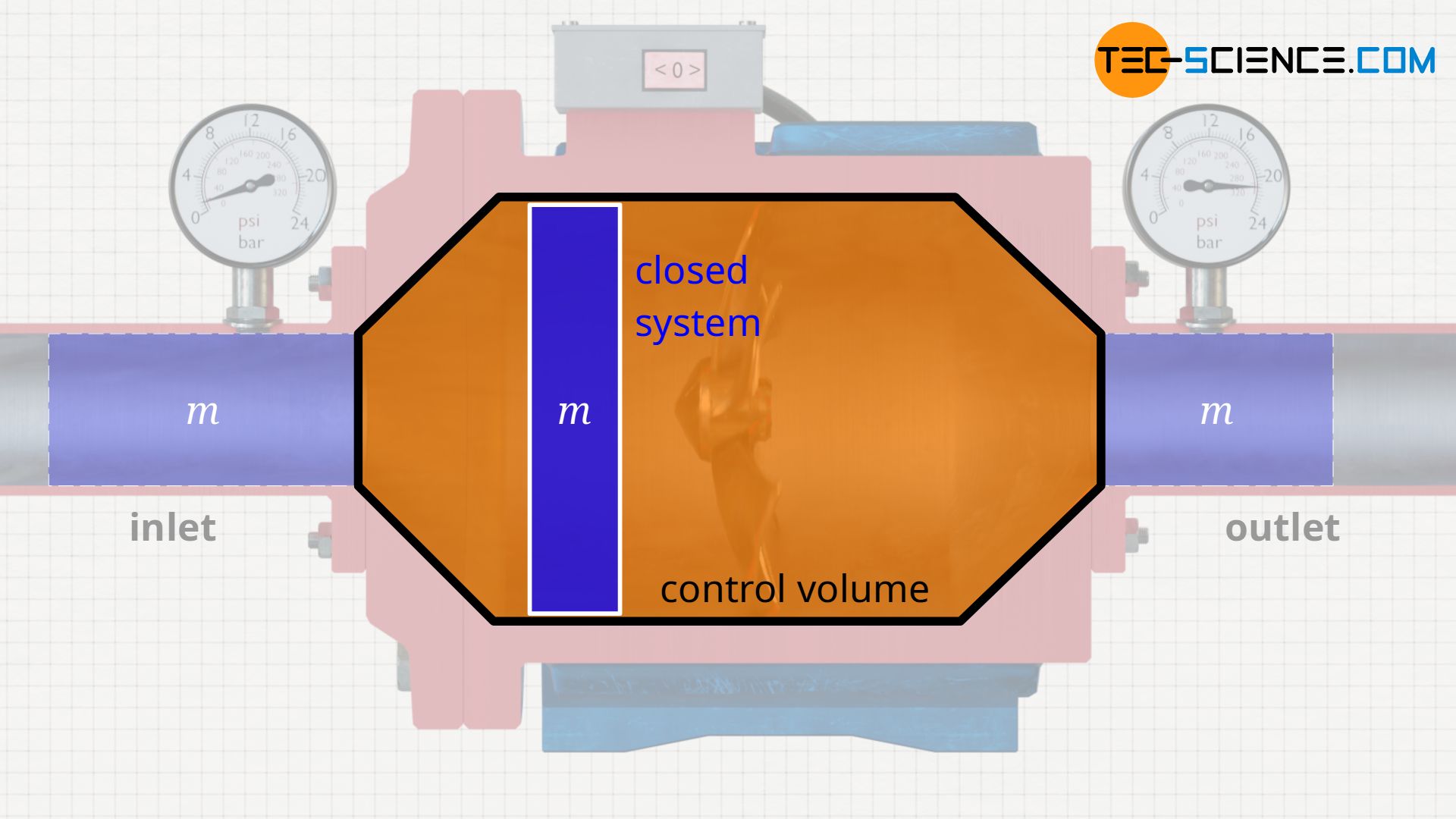
In such an approach, the different energy transfers become clear once again. The flow work refers only to the pushing through of the considered fluid mass due to the acting pressure difference at the control volume boundaries. The pressure-volume work, on the other hand, refers to the work done inside the control volume, i.e. to the work required to compress the considered fluid mass as it flows through the control volume.
Both energy transfers – flow work and pressure-volume work – are to be provided by the open system (e.g. by the motor of a compressor). Since both the pressure-volume work Wv and the flow work Wf are due to the process of pressure change inside the open system, the sum of both is also referred to as the flow process work Wp:
\begin{align}
\label{5715}
&W_\text{p} = W_\text{V} + W_\text{S} \\[5px]
\label{4461}
&\boxed{W_\text{p} =~ – \int\limits_{V_1}^{V_2}p(V)~\text{d}V + p_2~V_2 – p_1~V_1 }
\end{align}
or as specific flow process work wp (flow process work per unit mass):
\begin{align}
\label{8858}
&\boxed{w_\text{p} =~ – \int\limits_{v_1}^{v_2}p(v)~\text{d}v + p_2~v_2 – p_1~v_1 }
\end{align}
The fact that an open system also performs pressure-volume work in addition to flow work can be clearly demonstrated using a compressor. If the inlet and outlet of a compressor are closed for a short time, the compressor no longer has to perform flow work for this time, but the gas inside is still compressed. So there is still pressure-volume work to be done on the gas. The open system effectively becomes a closed system in which only pressure-volume work occurs.
Flow process work refers to the work of an open system to transfer a fluid through the system boundaries and change the volume.
In the simplest case, the flow process work corresponds to the total amount of work done in an open system. This flow process work must be provided by the driving motor in the case of a pump (for liquids) or in the case of a compressor (for gases). In this frictionless consideration, changes in kinetic and potential energy are neglected. This will be discussed in more detail in the section on shaft work.
Flow process work for incompressible fluids
Note that in an open system, the flow work and the pressure-volume work always occur together in general, namely as flow process work. After all, a pressure change is generally always associated with a volume change. Only in the theoretical case of a perfectly incompressible fluid would only the flow work occur in the open system. Because without a change in volume there is no pressure-volume work (dV=0). Therefore, only flow work must be done to push the incompressible fluid through the open system.
For such an incompressible fluid, the flow process work Wp when the volume V=V1=V2 flows through the open system results only from pressure change Δp generated by the open system:
\begin{align}
\label{2394}
&W_\text{p} =~ – \int\limits_{V_1}^{V_2}p(V)~\underbrace{\text{d}V}_{=0} + p_2~\underbrace{V_2}_{=V} – p_1~\underbrace{V_1}_{=V}=p_2~V-p_1~V = V~(p_2-p_1)= V \cdot \Delta p \\[5px]
\label{9679}
&\boxed{W_\text{p} = V\cdot\Delta p}~~~\text{applies only to incompressible fluids}
\end{align}
or as specific flow process work wp (flow process work per unit mass):
\begin{align}
\label{3376}
&\boxed{w_\text{p} = v\cdot\Delta p}~~~\text{applies only to incompressible fluids}
\end{align}
Even if such an incompressible case practically does not exist, it can still be considered as such for liquids in a very good approximation, since these are considered to be almost incompressible. For all other cases, especially for compressible fluids such as gases, the flow process work must be determined according to equation (\ref{4461}) or equation (\ref{8858}). However, this equation can be represented in a much simpler form. This becomes clear if one visualizes the process of an open system in a volume-pressure diagram. This will be discussed in more detail in the next section.
Flow process work represented in a volume-pressure diagram
In the following, a much more simpler formula for calculating the flow process work will be given. For this purpose, a gas is considered which is initially sucked in by a compressor with the volume V1 at a pressure p1. The gas is then compressed in the system to a volume V2. The process should run according to the curve shown in the p(V) diagram. After compression, the fluid volume V2 is pushed out of the compressor at a final pressure p2.
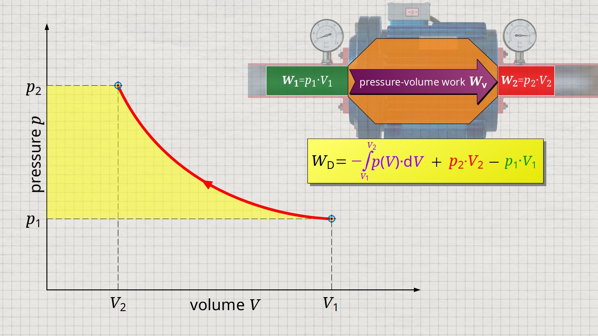
Equation (\ref{5715}) can be used to determine the flow process work. In this equation, the individual terms can be represented as areas in the p(V) diagram. The term of the pressure-volume work Wv = -∫p(V)⋅dV can be represented as the area under the curve (note that pressure-volume work is transferred to the gas during compression and this amount of work is thus mathematically positive)! According to equation (\ref{5715}) the term p2⋅V2 is added now, which can be represented as a rectangular area from the point (V2|p2) to the origin (0|0) (“push-out energy”). According to equation (ref{5715}), the rectangular area extending from the point (V1|p1) to the origin (0|0) is subtracted from this total area (“push-in energy”).
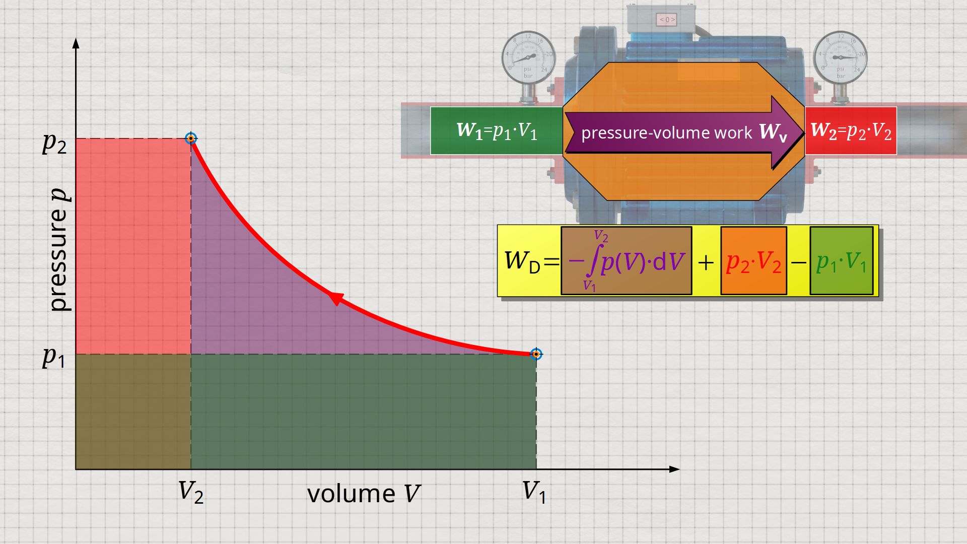
So, what is left is therefore only the area left of p(V)-curve up to pressure axis. This area left of the curve can therefore be interpreted as the flow process work!
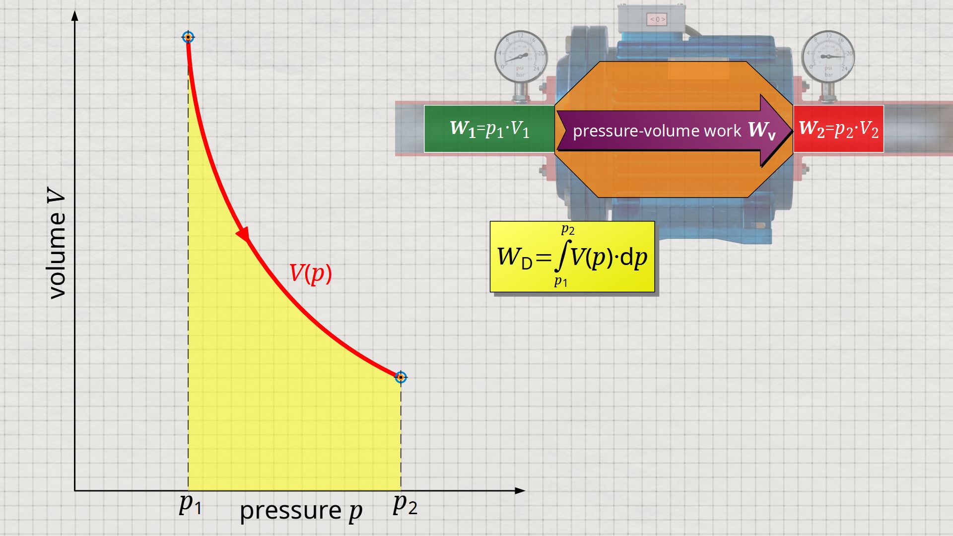
Mathematically, this area can be determined as the integral Wp=-∫V(p)⋅dp within the boundaries between p1 and p2. This becomes clear if one simply imagines the coordinate system rotated by 90° and mirrored at the same time. The horizontal axis then corresponds to the pressure and the vertical axis to the volume. In this case, the result is a V(p) function whose area under the curve corresponds to the flow process work Wp:
\begin{align}
\label{8449}
&\boxed{W_\text{p} = \int\limits_{p_1}^{p_2}V(p)~dp}~~~\text{applies to an open system}
\end{align}
Since open systems are usually described by specific quantities, it makes sense to represent the thermodynamic process also in specific diagram form. Therefore, the specific volume is usually plotted instead of the total volume. This means that the volume shown refers to a mass of 1 kg.
\begin{align}
\label{1956}
&\boxed{w_\text{p} = \int\limits_{p_1}^{p_2}v(p)~dp}~~~\text{applies to an open system}
\end{align}
Note: These equations show that for the calculation of the (specific) flow process work, the function p(V) must be known. In contrast to the flow work, the flow process work is thus dependent on the path along which the process takes place and is therefore a process quantity!

")

