Learn more about the difference between elevation head, pressure head, friction head (head loss) and total static head of a piping system in this article.
Static head of a pump
Pumps are used to deliver gases or liquids. These fluids are usually pumped from a lower level to a higher level. The pump is located between these levels. The pump creates a negative pressure on the so-called suction side so that the fluid is sucked in. The pump then puts the fluid under high pressure. At the outlet, the fluid is now pushed through the pipe to the higher level. In the following we will only consider incompressible fluids such as liquids.
The difference in height the liquid can overcome depends on the power of the pump, the density of the fluid to be pumped and the volume flow rate. To show this, we consider a vertical pipeline. Through this pipe, a fluid of density ϱ is pumped up from a tank. The water is discharged at the open end of the pipe. The difference in height to be overcome is denoted by H. Friction losses are neglected in the following.
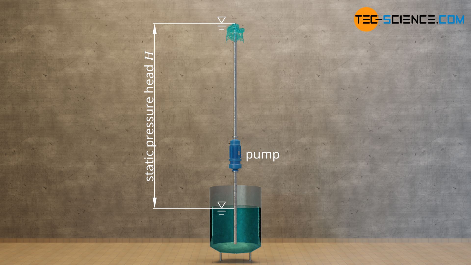
The time period until a liquid parcel has been delivered from the lower tank (liquid level) to the top of the pipe is denoted by t. Within this time t obviously once the total liquid of mass m=V⋅ϱ in the pipe must be lifted by the height H (the volume of the fluid inside the pipe is denoted by V). The amount of energy WH required for this is given by the following formula:
\begin{align}
&W_\text{H} = m \cdot g \cdot H ~~~\text{where}~~~m =V \cdot \rho \\[5px]
&W_\text{H} = V \cdot \rho \cdot g \cdot H ~~~~~\text{energy of the pump} \\[5px]
\end{align}
This energy is obviously converted within the time t, resulting in the following power PH that the pump delivers:
\begin{align}
&P_\text{H} = \frac{W_\text{H}}{t} \\[5px]
&P_\text{H} = \frac{V \cdot \rho \cdot g \cdot H}{t} \\[5px]
&P_\text{H} = \underbrace{\frac{ V}{t}}_{\dot V} \cdot \rho \cdot g \cdot H\\[5px]
&\boxed{P_\text{H} = \dot V \cdot \rho \cdot g \cdot H} ~~~~~\text{power of the pump} \\[5px]
\end{align}
When deriving this formula, it was exploited that the quotient of fluid volume V and time t corresponds to the delivered volume flow rate V*.
Conversely, this means: For a given power of the pump PH and volume flow rate V* to be delivered, the fluid can only overcame a certain height H, depending on the density of the fluid ϱ (at a greater height, the hydrostatic pressure of the fluid column would be greater than the pressure generated by the pump and the fluid could not be pumped any higher):
\begin{align}
&P_\text{H} = \frac{W_\text{H}}{t} \\[5px]
&P_\text{H} = \frac{V \cdot \rho \cdot g \cdot H}{t} \\[5px]
&P_\text{H} = \underbrace{\frac{ V}{t}}_{\dot V} \cdot \rho \cdot g \cdot H\\[5px]
\label{p}
&\boxed{H = \frac{P_\text{H}}{\dot V \cdot \rho \cdot g}} ~~~~~\text{static head of the pump} \\[5px]
\end{align}
This maximum height a pump can deliver is also called static pressure head, static head or pressure head of a pump.
The static head of a pump is the maximum height a pump can deliver in a loss-free case due to the mechanical power transferred to the fluid at a given volume flow rate and density!
Note that the static head of the pump does not take into account friction losses inside the pipe or pressure losses due to valves, bends, fittings, etc. This is because these losses cannot be directly attributed to the pump, but depend on the the piping system for which the pump is to be used. Manufacturers of pumps can therefore not take such losses into account anyway, as they do not know the operating conditions of the pump. For this reason, such pressure losses are taken into account by a so-called head loss of the piping system (more about this later).
Pump efficiency
The power PH in the above equations refers only to the power that the pump effectively delivers to the fluid, i.e. the power that is actually required to continuously lift the fluid to the height H! This power output is not identical with the power input Pin of the pump (power consumption), i.e. the power that an electric pump, for example, has to draw from the mains.
It is therefore necessary to take into account conversion losses that occur when converting the supplied electrical power into mechanical power for transporting the fluid. Also flow losses in the pump due to turbulence must be taken into account, especially at high volume flow rates. All this is summarized in a pump efficiency η:
\begin{align}
&\boxed{P_\text{H} = P_\text{in} \cdot \eta} \\[5px]
\end{align}
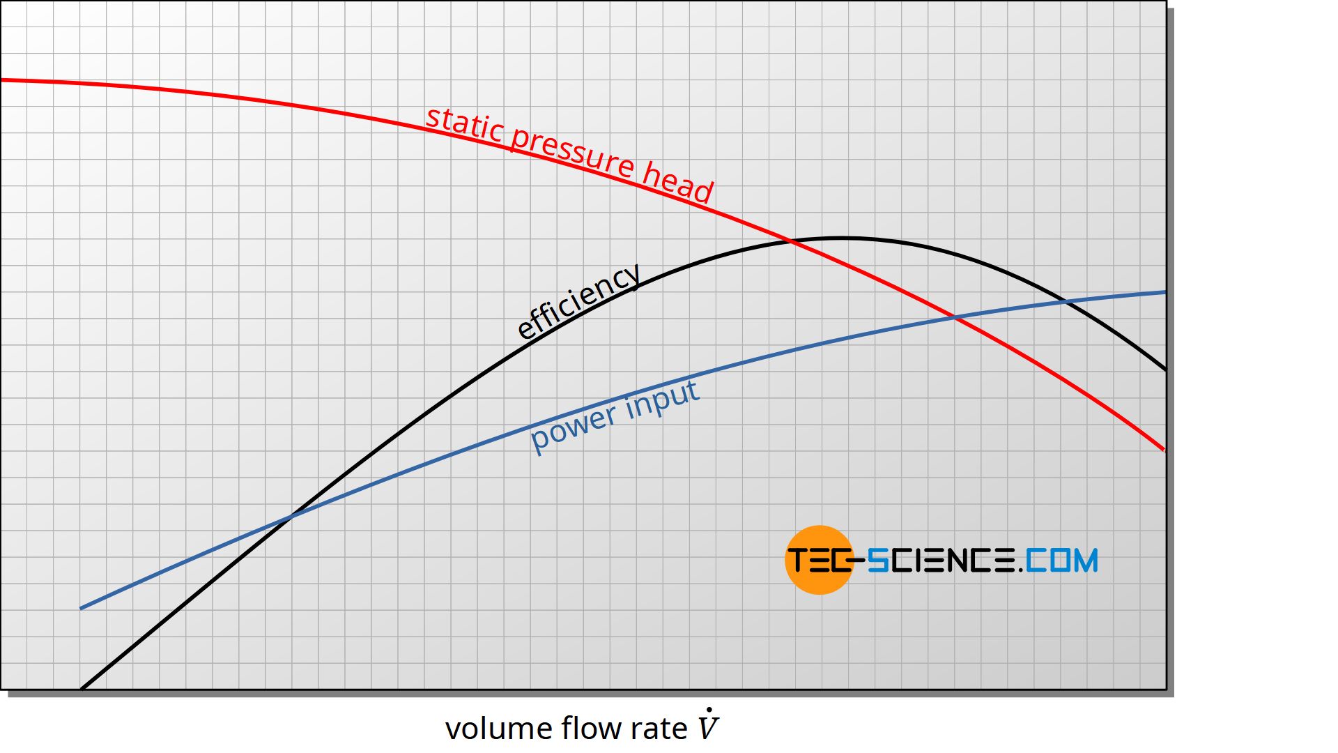
The pump efficiency is not a constant value, but depends on the volume flow rate! The efficiency first increases with increasing flow rate and then decreases again from a maximum point due to turbulences and the associated flow losses. Typical maximum efficiencies for pumps are between 70 % and 90 %.
The figure below shows for a given rotational speed of a centrifugal pump the typical curves for pressure head, pump efficiency and power consumption of the pump as a function of volume flow rate. Note that such curves are only valid for certain rotational speed of the pump.
Static head of a piping system
Elevation head (geodetic head)
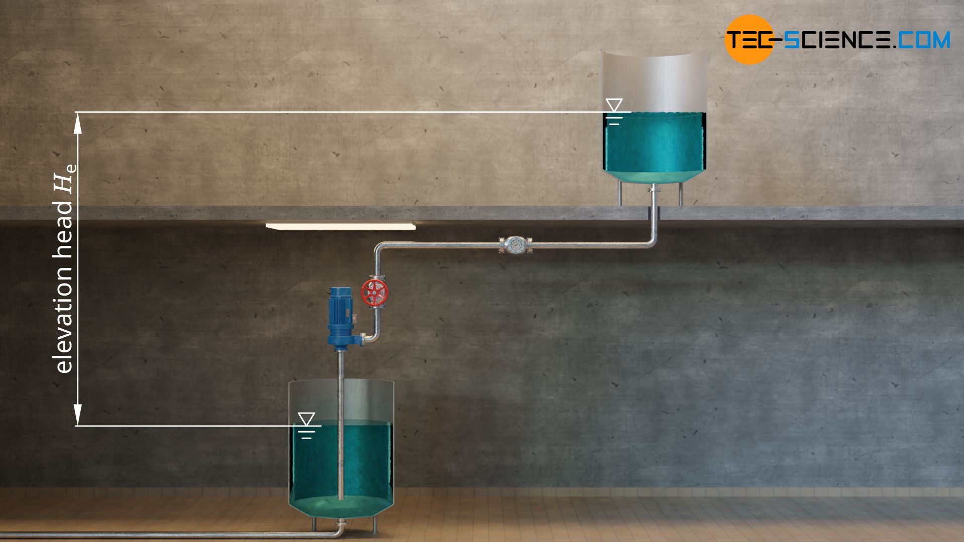
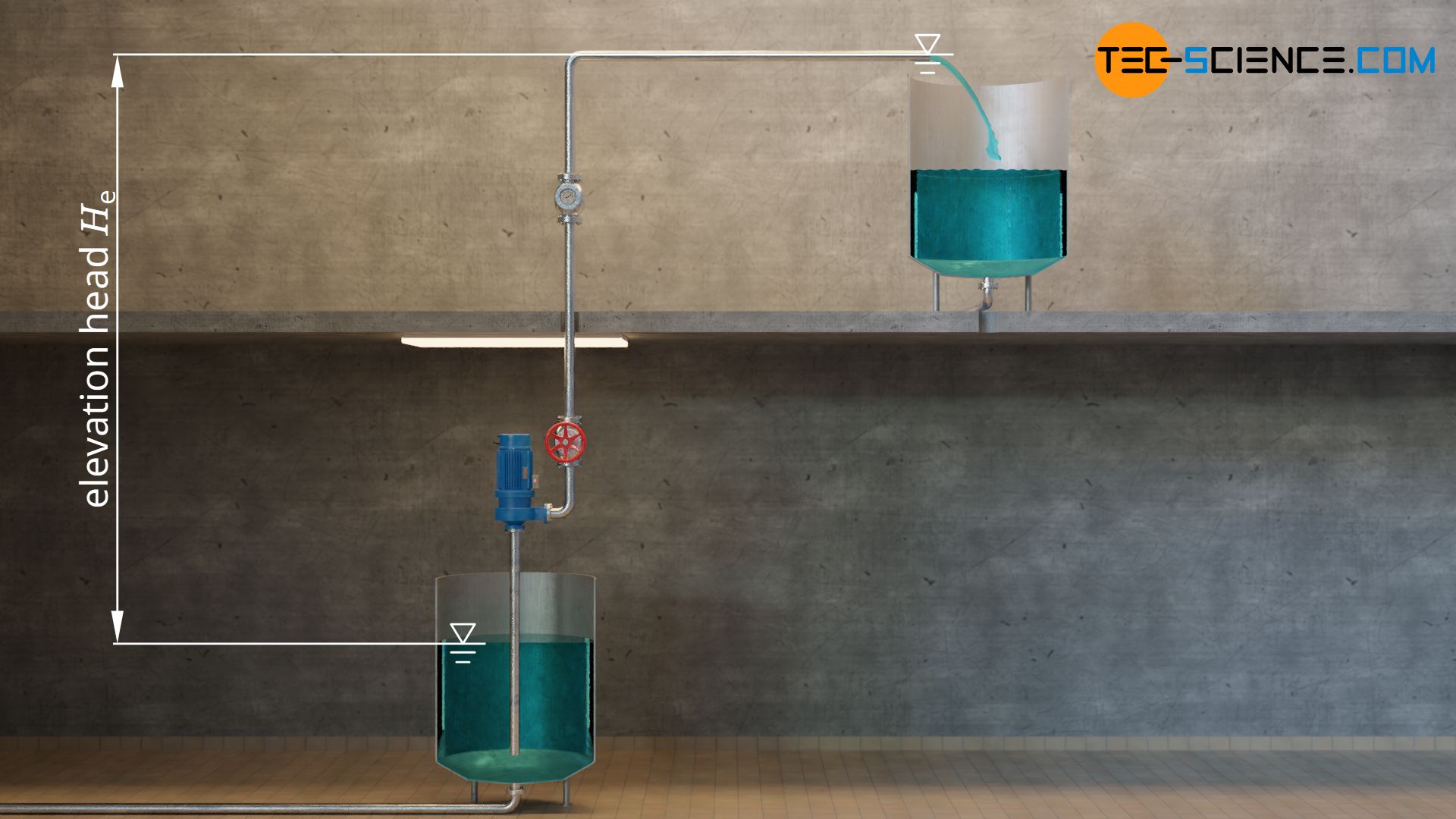
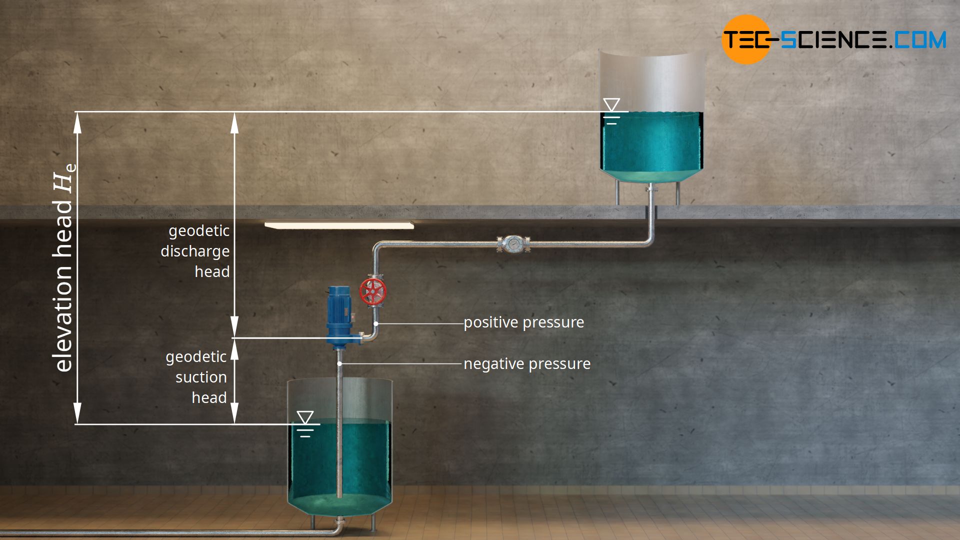
The physical difference in height between a lower placed and a higher placed basin is called elevation head or geodetic head He. The respective liquid levels serve as reference points for the elevation head, provided that the higher-lying tank is filled from below. If it is filled from above, the reference point is the point at which the liquid flows out of the pipe. For the lower basin, it does not matter how deep the suction pipe is immersed in the liquid. The liquid surface must always be taken as a basis, since the liquid in the suction pipe rises to the outer liquid level by itself anyway without the help of the pump.
The elevation head of a piping system can be further divided into a suction head on the suction side of the pumpe and a discharge head on the discharge side of the pump. Both heads together comprise the elevation head of the piping system.
The elevation head of a piping system is the physical difference in height between a lower and a higher liquid level! It results from the sum of the suction head and discharge head.
In order for liquids to be pumped, the static head of the pump must always be greater than the elevation head of the system. However, this only applies if there are no friction losses or flow losses in the pipe due to installed components such as valves, bends, fittings or measuring instruments. Furthermore, the maximum suction head is limited by physical conditions.
Maximum geodetic suction head
On the suction side, the pump works like a drinking straw. This means that the pump does not suck in liquid at all. Rather, the (ambient) pressure on the surface of the liquid pushes the fluid into the pump. Since the ambient pressure is finite, even when a perfect vacuum is created, it is not possible to overcome any suction head. By neglecting friction and flow losses, the maximum suction lift is determined according to the following formula (see article How does a drinking straw work? for the derivation of this formula).
\begin{align}
\label{hmax}
&\boxed{h_\text{s,max} = \frac{p_0}{\rho \cdot g} } ~~~~~\text{maximum suction head} \\[5px]
\end{align}
In this formula, p0 denotes the (ambient) pressure on the liquid surface and ϱ denotes the density of the liquid. For pumping water with a density of ϱ = 1000 kg/m³ the maximum suction head at an ambient pressure of 1 bar is thus 10 meters.
However, due to the fact that no pump can create a perfect vacuum and due to the viscosity of the pumped liquid, friction losses are inevitable, the maximum geodetic suction head for water is in practice only 8 metres. Note that when the tank is closed, the ambient pressure can be artificially increased, so that higher suction heads are possible.
Unlike the suction head, the discharge head on the discharge side of the pump is in principle not limited to a maximum value. Depending on the pressure generated on the discharge side, (almost) any discharge head can be achieved.
Friction head (head loss)
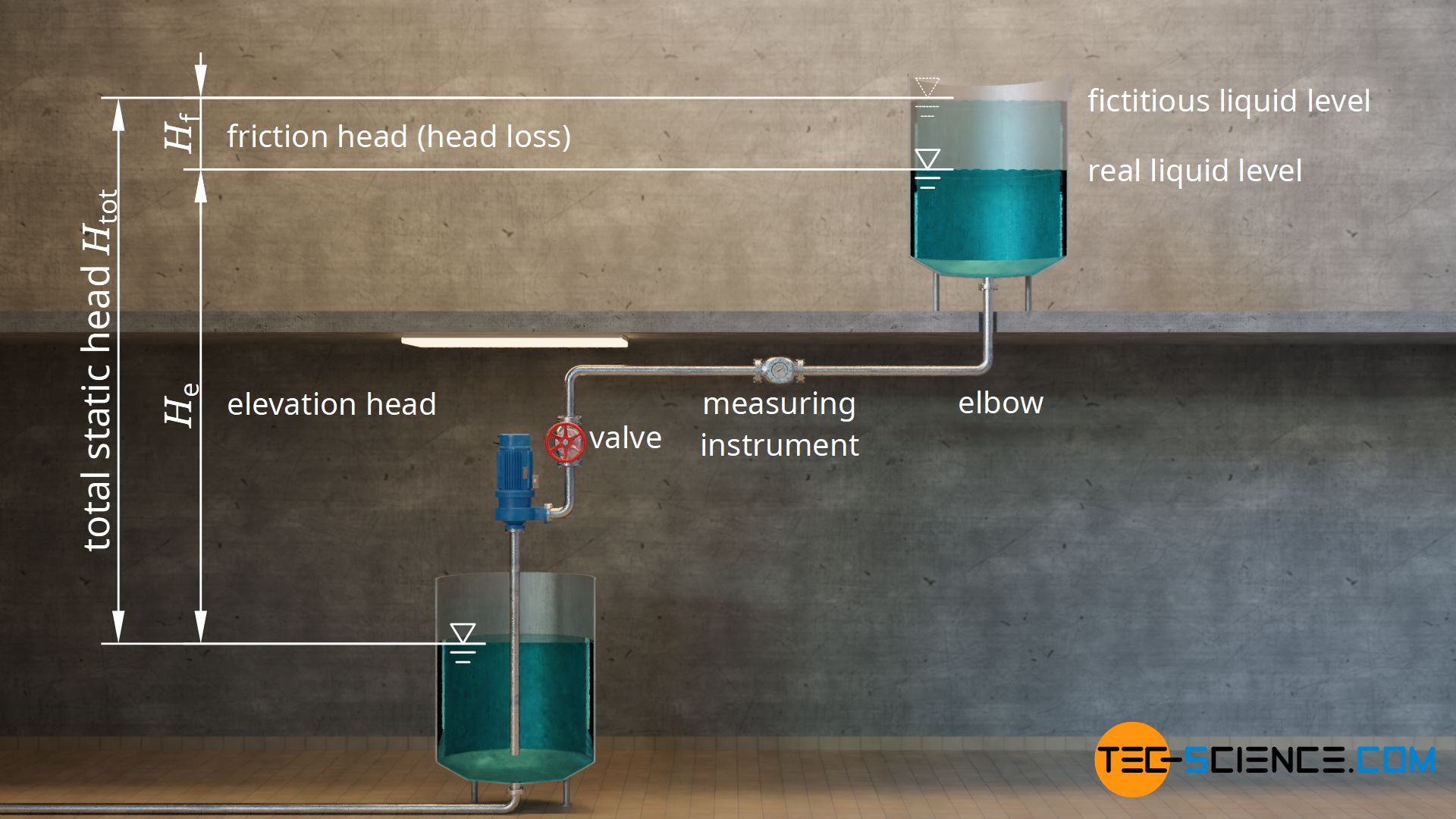
As already mentioned, in reality friction and flow losses in the piping system must be taken into account. So in practice, the pump must transfer a greater power to the fluid than in the friction-free case. Taking friction into account, the real system behaves as if a fictitious frictionless system had a higher head. This additional (fictitious) head, which includes friction and flow losses, is called friction head or head loss Hf.
If Pf denotes the power loss that occurs with a certain volumetric flow rate V*, then the friction head Hf can be determined according to equation (\ref{p}):
\begin{align}
&\boxed{H_\text{f} = \frac{P_\text{f}}{\dot V \cdot \rho \cdot g} } ~~~~~\text{friction head (head loss)} \\[5px]
\end{align}
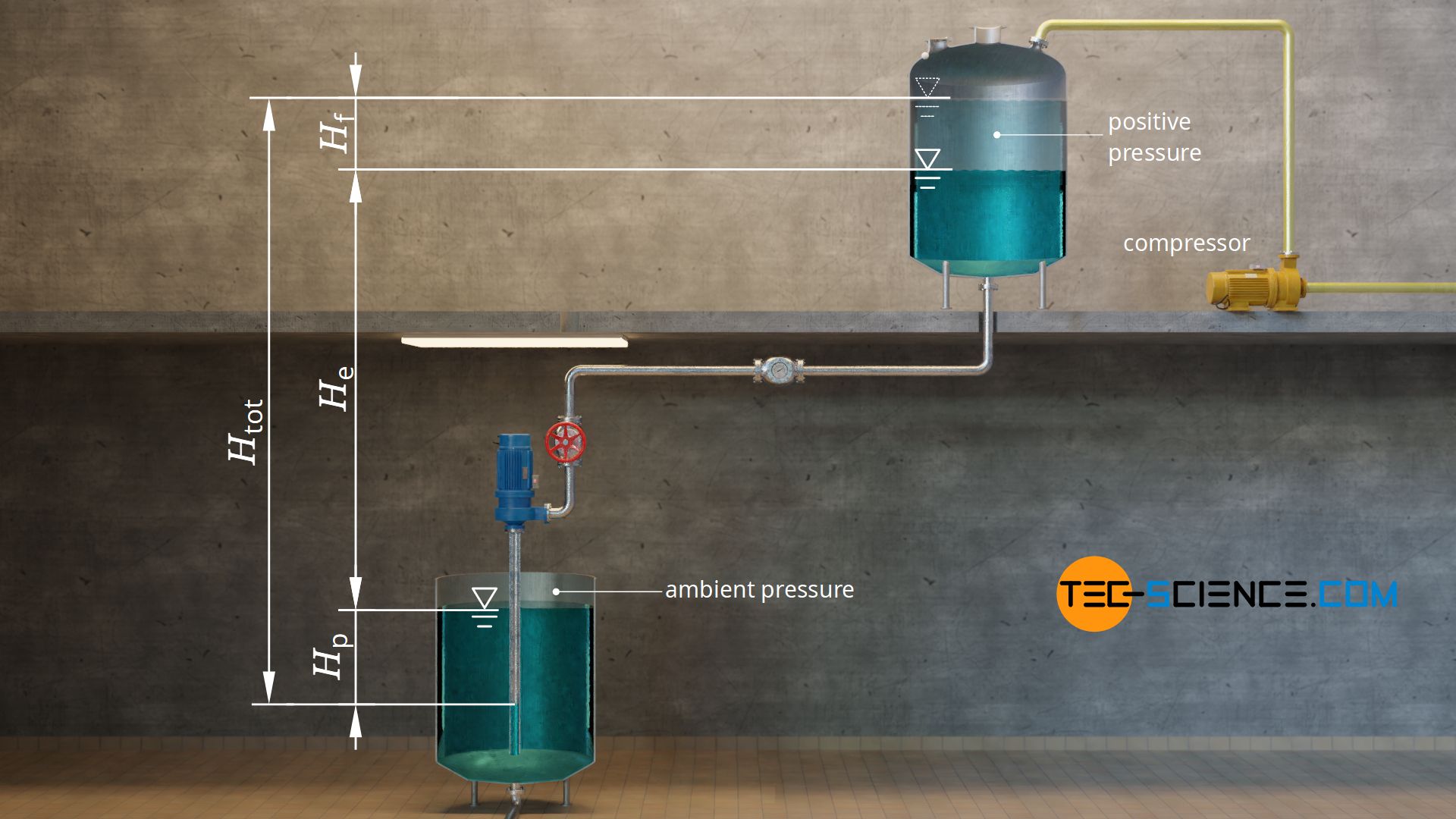
The (fictitious) total static head of the piping system Htot is therefore greater than the elevation head He by the amount of the friction head Hf:
\begin{align}
&\boxed{H_\text{tot} = H_\text{e} + H_\text{f}} ~~~~~\text{total static head of the piping system} \\[5px]
\end{align}
So one has to compare the static head of the pump with the (fictitious) static head of the piping system when it comes to selecting a suitable pump. The static head of the pump must be greater than the total static head of the system in order for the fluid to be conveyed. However, this does not yet take into account the fact that different pressures can exist on the liquid surface in the upper and lower tanks. For this reason, a pressure head must generally also be taken into account, which will be discussed in more detail in the next section.
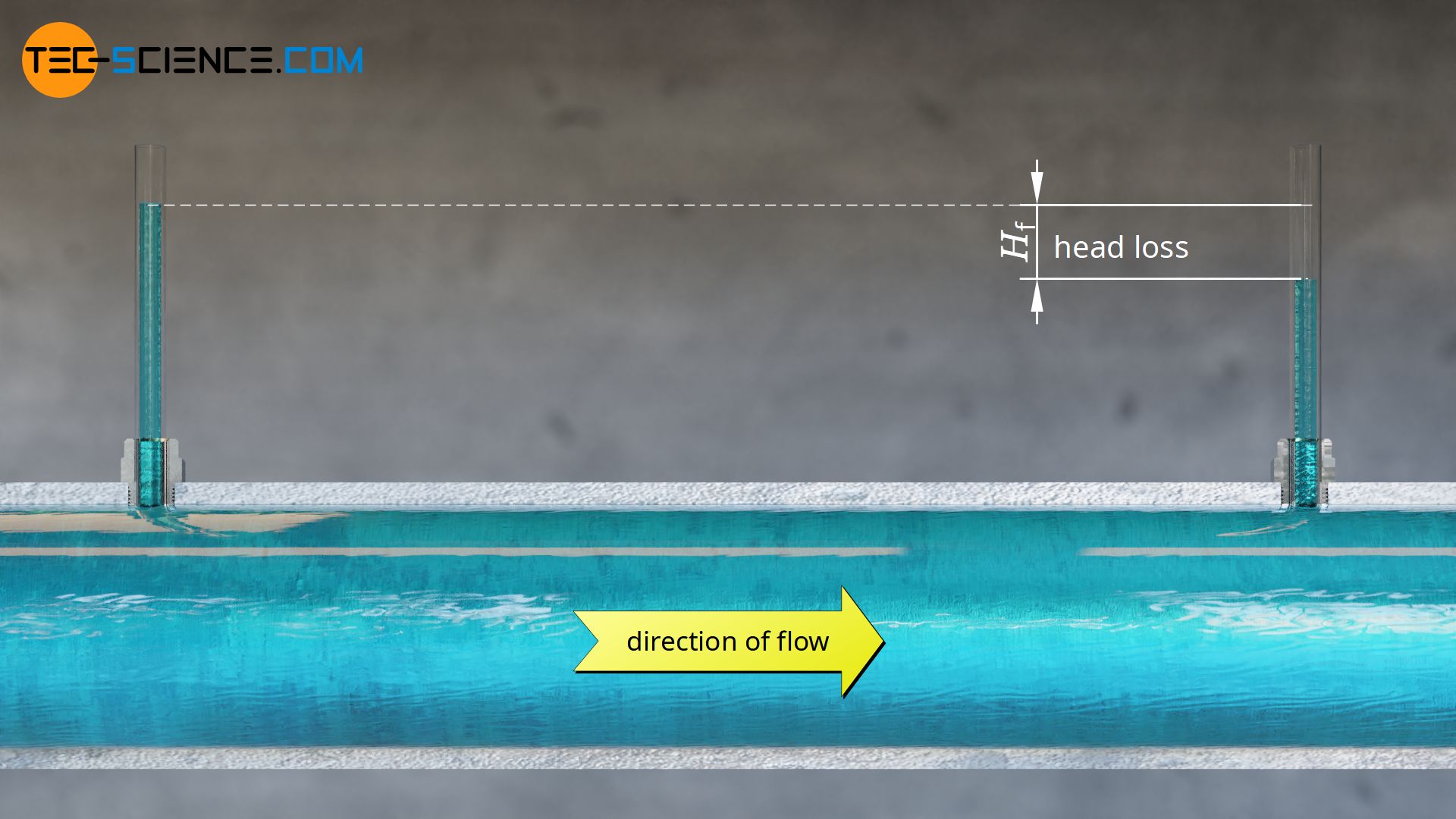
Even in a horizontal pipe, friction inevitably occur due to the viscosity of the fluid. In this case, the associated head loss can indeed be shown very clearly. One can imagine small vertical tubes attached to the pipe. Due to the static pressure in the flowing liquid, the fluid in the vertical tubes is pressed upwards by a certain amount. Due to the friction losses in the pipe, however, the static pressure downstream decreases (assuming a constant pipe cross-section). The fluid in a downstream tube only reaches a lower height. The difference in the liquid levels corresponds to the head loss of the horizontal pipe.
Pressure head
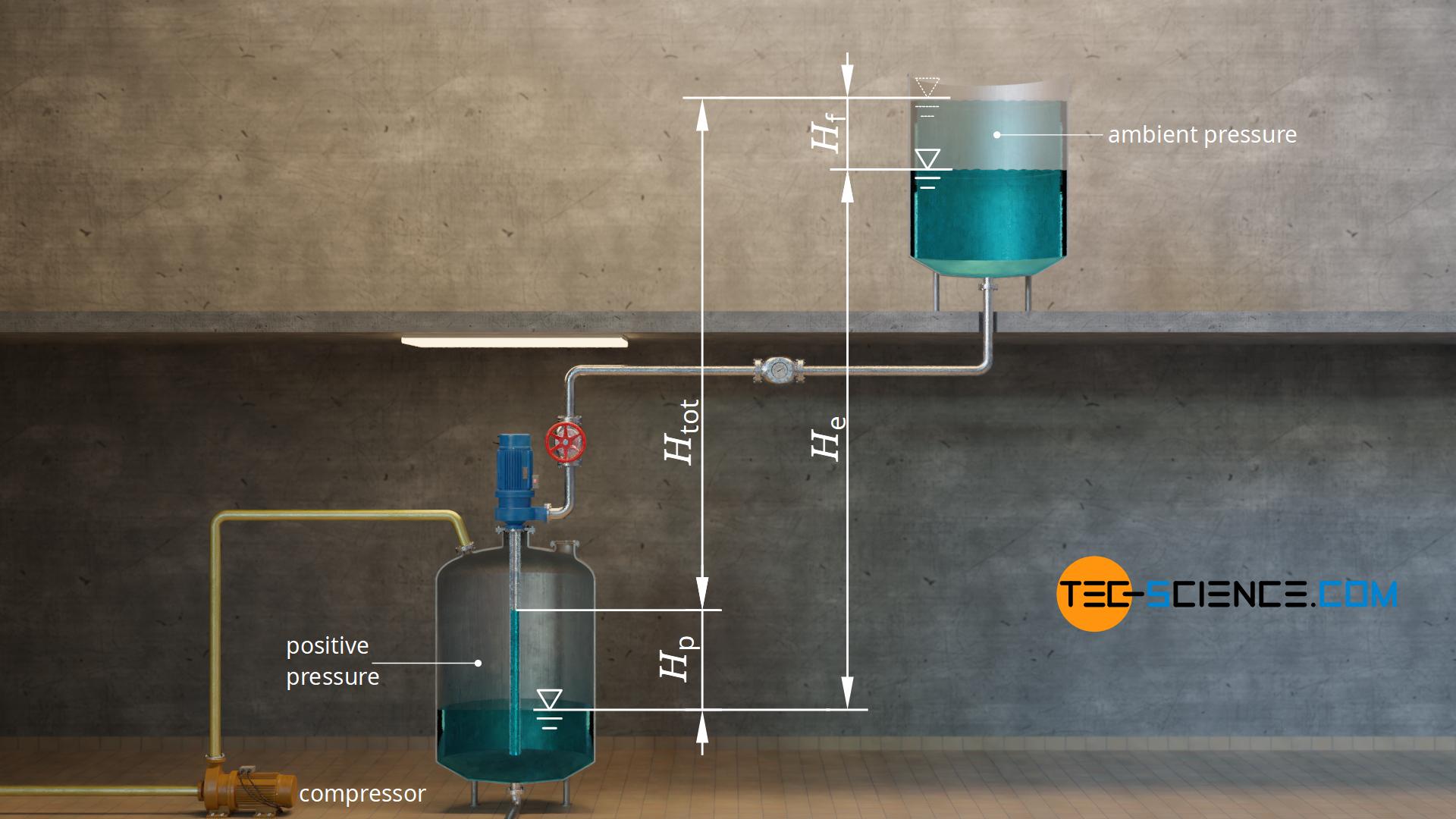
Imagine the following situation. Water is to be pumped from a closed tank to an open tank 6 meters higher up. In the closed tank there is a positive pressure (overpressure) created by compressor. Even without the presence of a pump, this positive pressure will push the water upwards. At an overpressure of 0,1 bar the water theoretically rises to a height of 1 meter above the liquid level [see formula (\ref{hmax})]. So the pump only has to overcome the last 5 meters of height. From an energy point of view, the system has a total static head of only 5 meters from the pump’s point of view (without taking into account head loss).
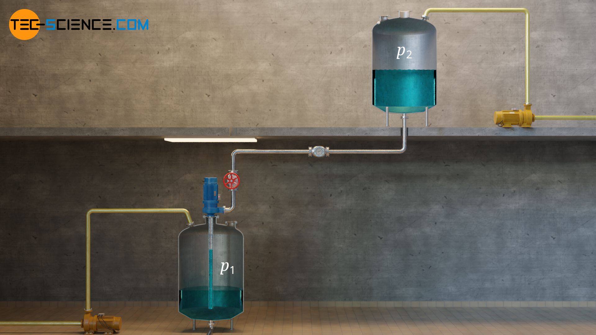
Conversely, the total static head of the system increases when the lower tank is open and a positive pressure is generated in the higher tank. In this case the higher pressure in the upper tank pushes the water in the pipe downwards. This means that the pump now has to overcome a much greater difference in height. The effects only balance each other out if the pressures in both tanks are the same (for example ambient pressure in both tanks). Even without external compressors, pressure differences occur in closed tanks, since the air volume in the tank also changes when the liquid level changes, without air being able to escape or flow in.
The increased head or the reduced head due to the pressure difference Δp between the two tanks is called pressure head Hp. The pressure difference is determined by the difference between the pressure in the upper reservoir p2 and the pressure in the lower reservoir p1 In this way, the sign is also reproduced correctly, so that in the event of a negative pressure at the upper reservoir (or a positive pressure at the lower reservoir) a negative pressure head results, which reduces the total static head of the system.
\begin{align}
&H_\text{p} = \frac{\Delta p}{\rho \cdot g} \\[5px]
&\boxed{H_\text{p} = \frac{p_\text{2}-p_\text{1}}{\rho \cdot g} } ~~~~~\text{pressure head} \\[5px]
\end{align}
The total head of the system Htot is thus generally determined from the sum of the elevation head He, friction head Hf and pressure head Hp:
\begin{align}
&\boxed{H_\text{tot} = H_\text{e} + H_\text{V} + H_\text{p} } ~~~~~\text{total static head of the piping system} \\[5px]
\end{align}
Head as an energy per unit weight
At this point the head according to equation (\ref{p}) shall be examined more closely and interpreted somewhat differently. For this purpose it will be exploited that power is defined as energy per unit time and volume flow flow ist defined as liquid volume per unit time.
\begin{align}
\require{cancel}
&H = \frac{P_\text{H}}{\dot V \cdot \rho \cdot g} ~~~~~\text{where}~~~P_\text{H}=\frac{W_\text{H}}{t}~~~~~\text{and}~~~\dot V = \frac{V}{t}~~~\text{:}\\[5px]
&H = \frac{\frac{W_\text{H}}{\bcancel{t}}}{\frac{V}{\bcancel{t}} \cdot \rho \cdot g} \\[5px]
&H = \frac{W_\text{H}}{\underbrace{V \cdot \rho}_{m} \cdot g} \\[5px]
&H = \frac{W_\text{H}}{m \cdot g} \\[5px]
&\boxed{H = \frac{W_\text{H}}{F_\text{g}}} \\[5px]
\end{align}
This formula shows that head can be interpreted as an energy per unit weight. Therefore, the following statements apply:
- static head of the pump = Energy of the pump transferred to a fluid element (related to the weight of the fluid element).
- static head of the piping = Energy required to deliver a fluid element (related to the weight of the fluid element).
System characteristic curve
While elevation head and pressure head are constant values of a piping system, the friction head or head loss depends on the volume flow rate. The pressure losses increase with increasing flow rate. In the article Pressure Loss in pipe systems (Darcy friction factor) the following equation has been derived, which describes the pressure loss Δpf of a pipe with the friction factor f, the inner diameter d and the length L:
\begin{align}
& \boxed{\Delta p_\text{f} = f \cdot \frac{8\rho~L}{\pi^2} \cdot \frac{\dot{V}^2}{d^5}} ~~~\text{pressure loss in a straight pipe section} \\[5px]
\end{align}
This pressure loss is inevitably associated with a loss of mechanical energy and a corresponding head loss. The head loss thus increases (approximately) quadratically with the volume flow rate. “Approximately” because the friction factor is in turn influenced by the volume flow rate. The figure below shows qualitatively the characteristic curve of the total static head of a piping system as a function of the volume flow rate.
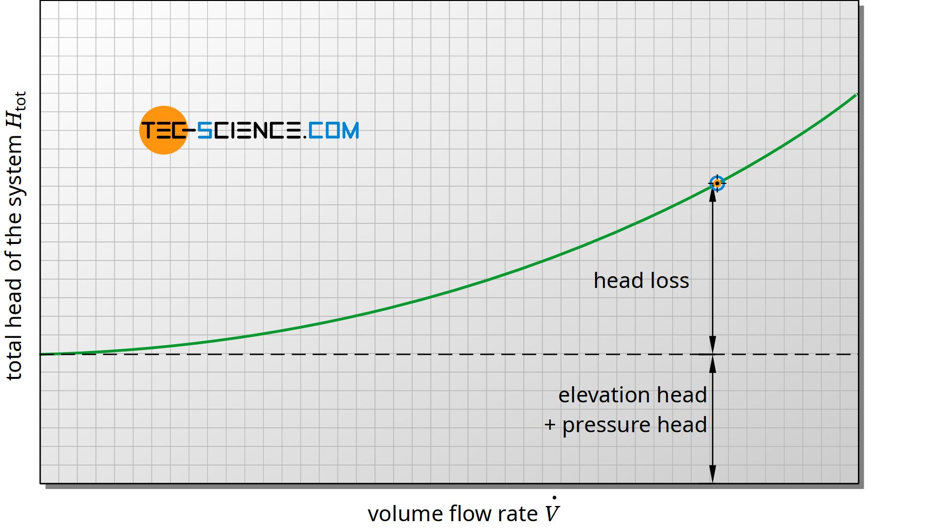
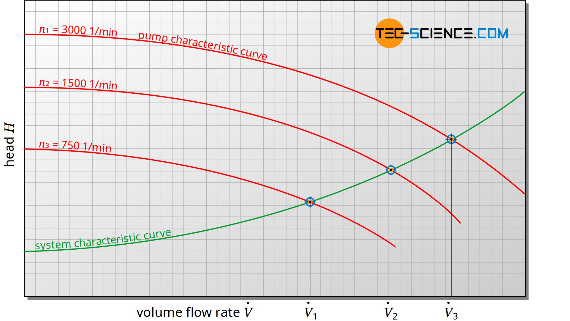
While the total head of the system increases with increasing volume flow rate, the static head of the pump decreases due to the increasing flow losses within the pump. During operation of the pump, depending on the volume flow rate, a common operating point (working point) is established which corresponds to the point of intersection between the pump characteristic curve and the system characteristic curve.
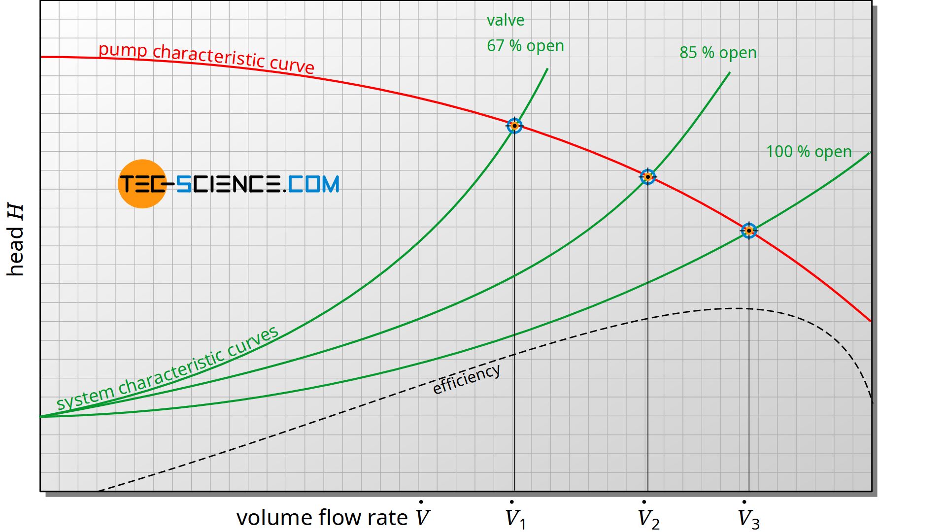
The system characteristic curve can be influenced by a throttle valve to control the flow rate. However, it must be noted that a centrifugal pump has a maximum efficiency at a certain volume flow rate. For energy-efficient operation, the working point should be as close as possible to this point of maximum efficiency. However, a change in the system characteristic curve caused by a throttle valve usually has a negative effect on the operating point – lower efficiencies result from the greater flow losses due to the throttling. A change in the rotational speed of the pump to control the volume flow rate can therefore be more sensible at this point.
")


")
")
