In the case of a boundary layer separation (flow separation), the flow can no longer follow the profile of the body around which it flows and separates turbulently from it.
Introduction
When a fluid flows around a body, forces act between the fluid and the surface due to the viscosity. These intermolecular forces are the caue for the drag, among other things. However, due to the forces acting, the surface of the solid body also tries to bind the fluid to itself. This also leads to the fluid adhering to the surface (no-slip condition). The layer above this adherent fluid layer will not be able to simply tear itself away from it, because intermolecular attraction and pressure forces also act between the layers. As a result, any flow flowing around a body is tempted to follow the profile of the surface.
When flowing around a body, the fluid tries to follow the profile of the surface!
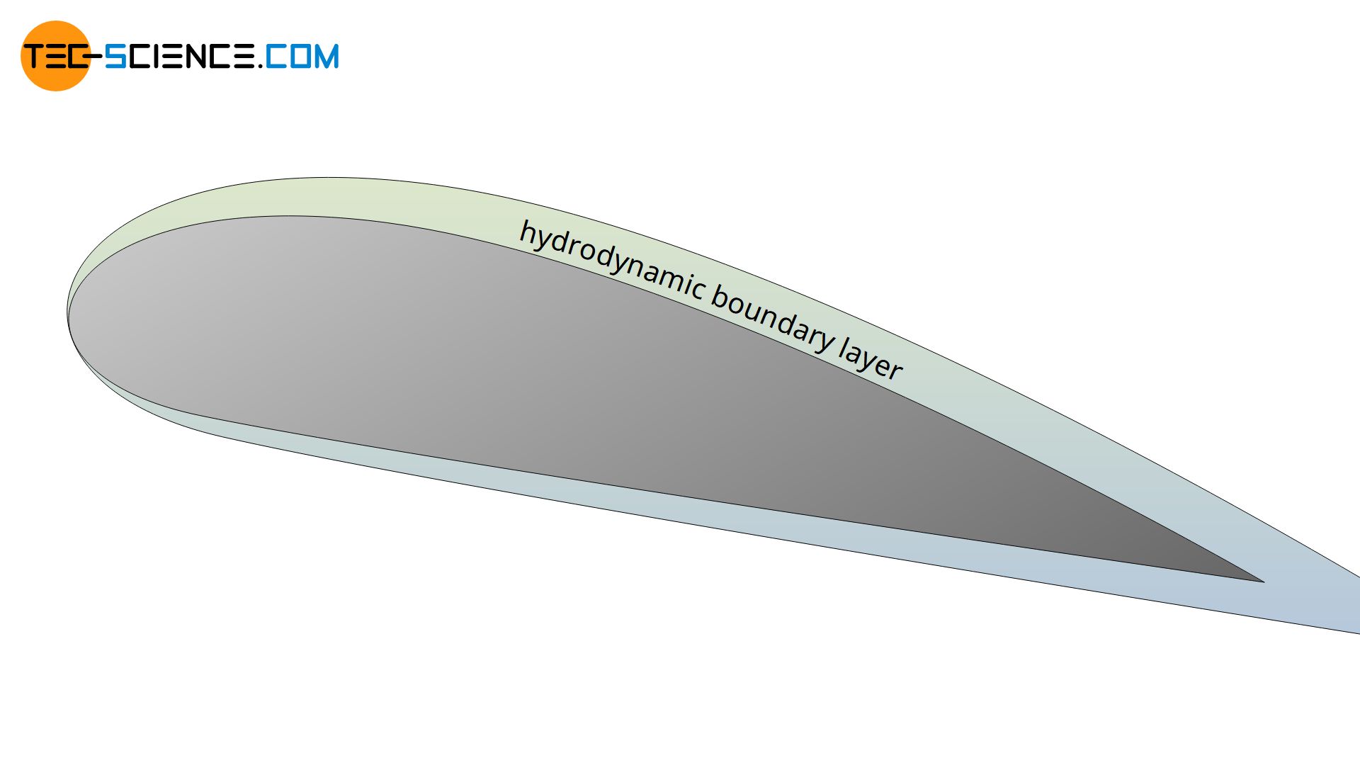
As long as the contour of a body has smooth transitions and the internal cohesion of the fluid (viscosity) is large enough to resist the inertial forces, a flow can follow the contour. A typical hydrodynamic boundary layer develops around the body, the thickness of which is largely influenced by the viscosity.
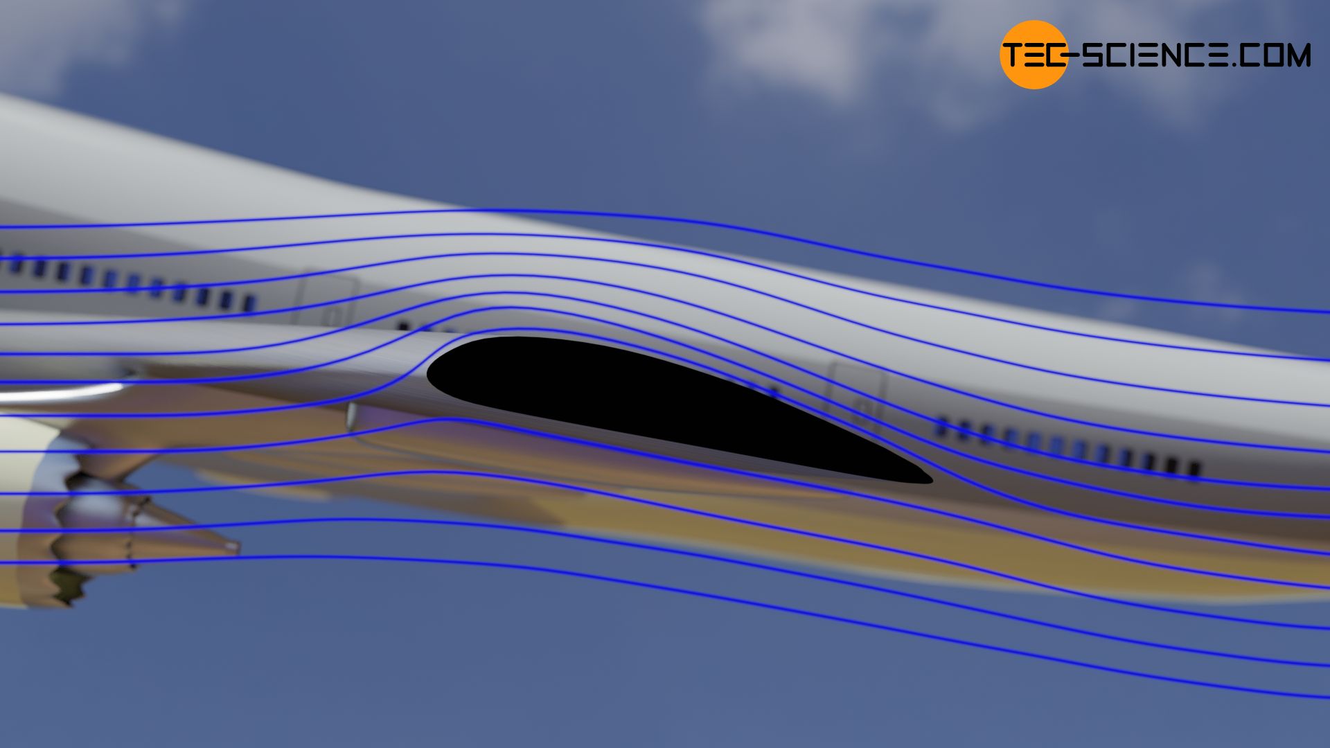
In the case of sharp transitions or when flowing around blunt bodies, however, the fluid is often no longer able to follow the profile. The boundary layer or flow begins to detach itself from the body surface. This is referred to as a boundary layer separation or flow separation. Downstream of the separation point, vortices often form, resulting in a turbulent flow. A flow separation is particularly dangerous on the wings of an aircraft, as this also causes a loss of lift and the aircraft is in danger of crashing. In aviation such a dangerous flow separation is called stall.
In the case of a boundary layer separation (flow separation), the flow can no longer follow the profile of the body around which it flows and separates turbulently from it.
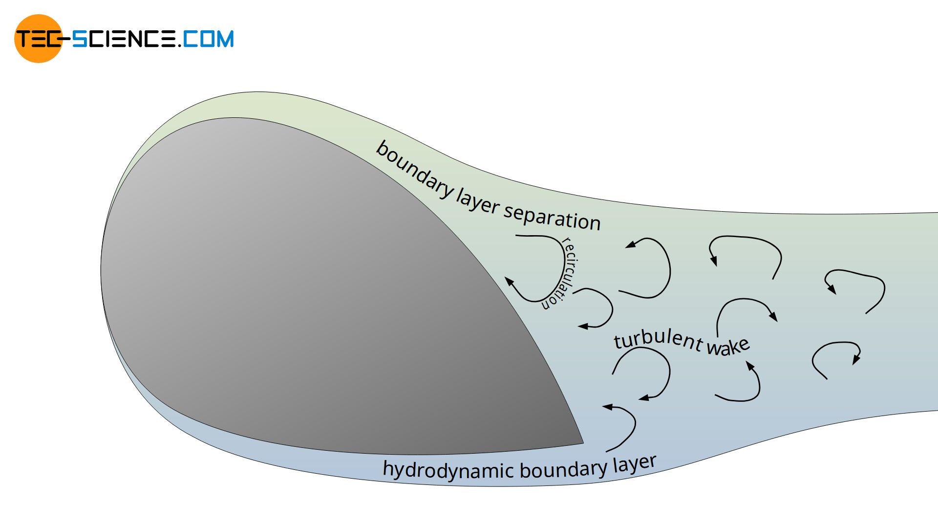
As already mentioned, the boundary layer separation is obvious at sharp transitions. However, a stall can also occur even with smooth transitions. This is the case if the flow slows down considerably when flowing around a body. As a result, the static pressure can increase so much that it suddenly pushes the flow in the opposite direction. This results in a recirculation area, which causes a flow separation. Since a deceleration of the fluid occurs with every body, the danger of boundary layer separation therefore also exists with every body around which the fluid flows!
The Reynolds number plays a decisive role here, since it describes the relationship between the existing inertial forces and the acting viscosity forces in a fluid. The higher the Reynolds number, the greater the inertia compared to the viscosity and the higher the risk of boundary layer separation. If the Reynolds numbers are sufficiently high, even with streamlined bodies, flow separation will eventually be unavoidable.
Fluidic processes
Using the example of the flow around a cylinder, the processes in the fluid are explained in more detail. In the ideal case, a laminar boundary layer forms around the cylinder and the flow is completely attached to the surface. The laminar flow in the boundary layer displaces the undisturbed external flow. Conversely, however, the external flow imposes its pressure on the boundary layer and thus influences its course. The flow in the boundary layer and in the undisturbed external flow therefore influence each other.
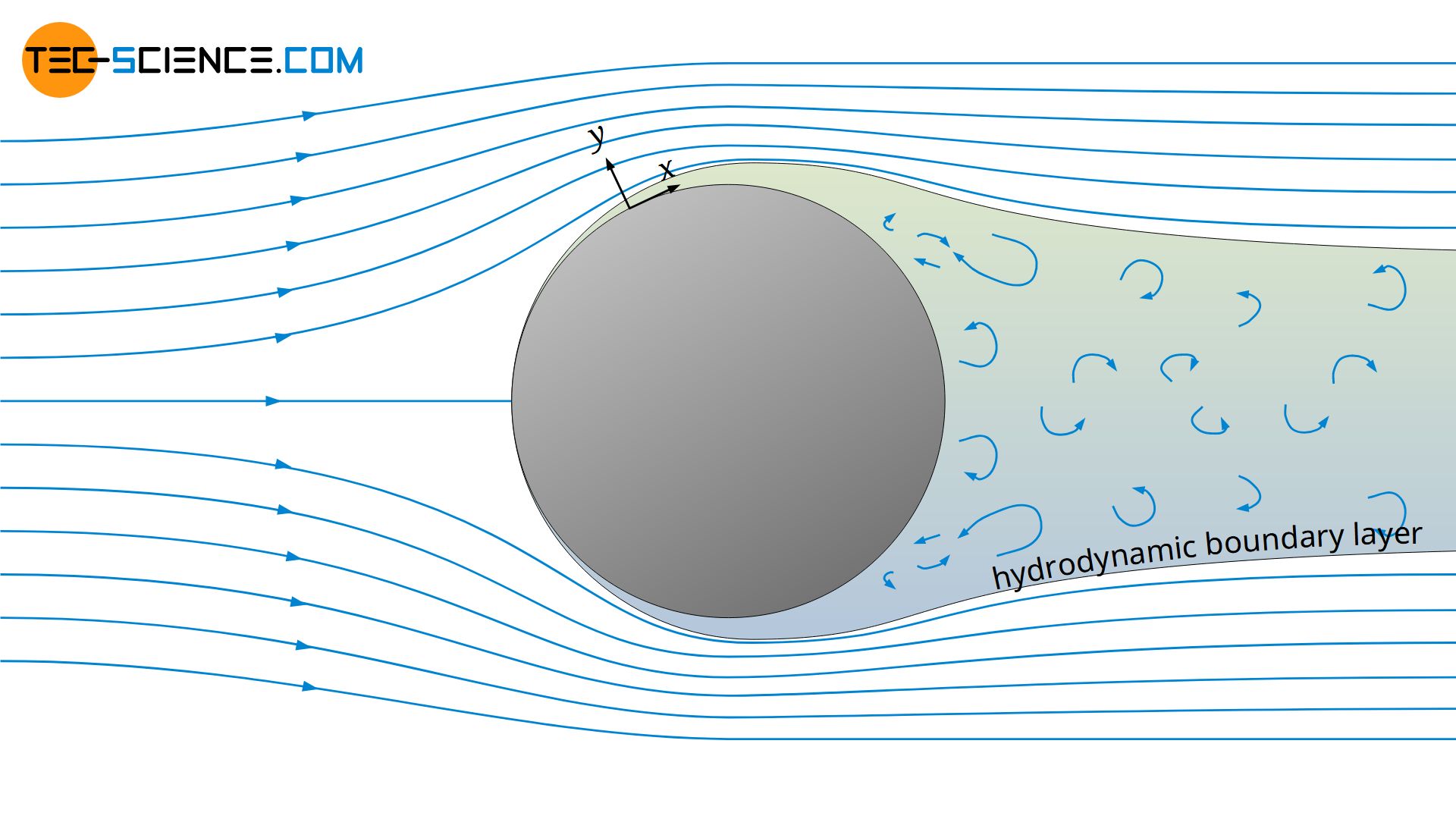
Within the boundary layer, the imposed pressure does (almost) not change in the direction perpendicular to the surface. The pressure gradient in y-direction is therefore negligible (∂p/∂y). Only along the surface in the direction of the flow the pressure changes. According to the Bernoulli’s principle, the pressure depends on the velocity of the undisturbed external flow. When flowing around a flat plate, the velocity of the undisturbed external flow would be constant and thus also the pressure along the x-direction (∂p/∂x=0).
When flowing around a curved body, however, the flow velocity changes and thus there is also a pressure gradient in x-direction. In case of a cylinder, the fluid at first is forced upwards and downwards in order to flow around the cylinder. However, according to the continuity equation (conservation of mass), the same mass must still be moved around the cylinder, so that the flow velocity increases as a result. At the thickest point of the cylinder, the maximum flow velocity is finally reached.
However, according to Bernoulli’s principle, a change in kinetic energy is directly linked to a change in static pressure. In this case, the increase in kinetic energy is at the expense of the pressure (energy). The static pressure thus decreases to a minimum up to the thickest point of the cylinder. The pressure gradient in x-direction is negativ in this area (∂p/∂x<0).
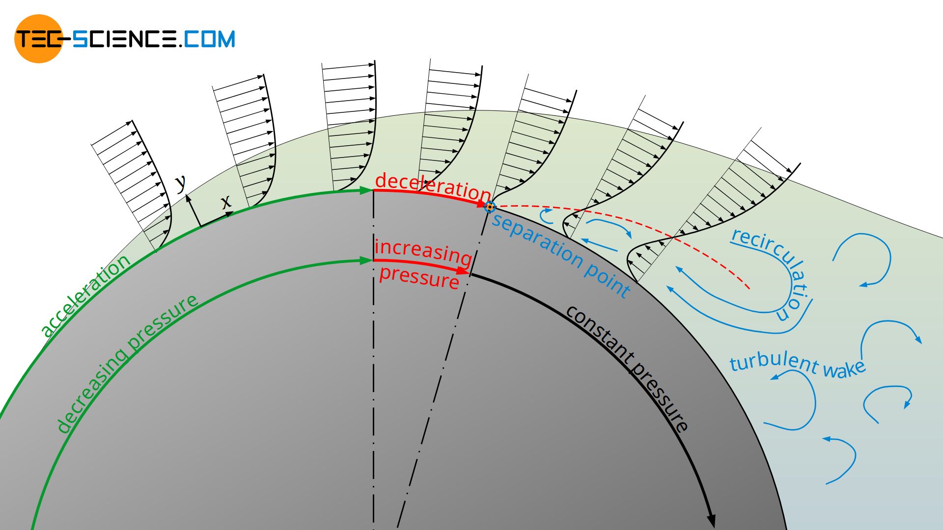
Now the effective cross-section of the flow increases, as the cylinder cross-section decreases (the flow has more space, so to speak). The flow slows down and the static pressure rises again in the x-direction to finally reach the level of the atmosphere (∂p/∂x>0). This pressure gradient acting against the actual direction of flow is called adverse pressure gradient. Note that this pressure gradient is mathematically positive and not negative, as the pressure increases in the positive x-direction.
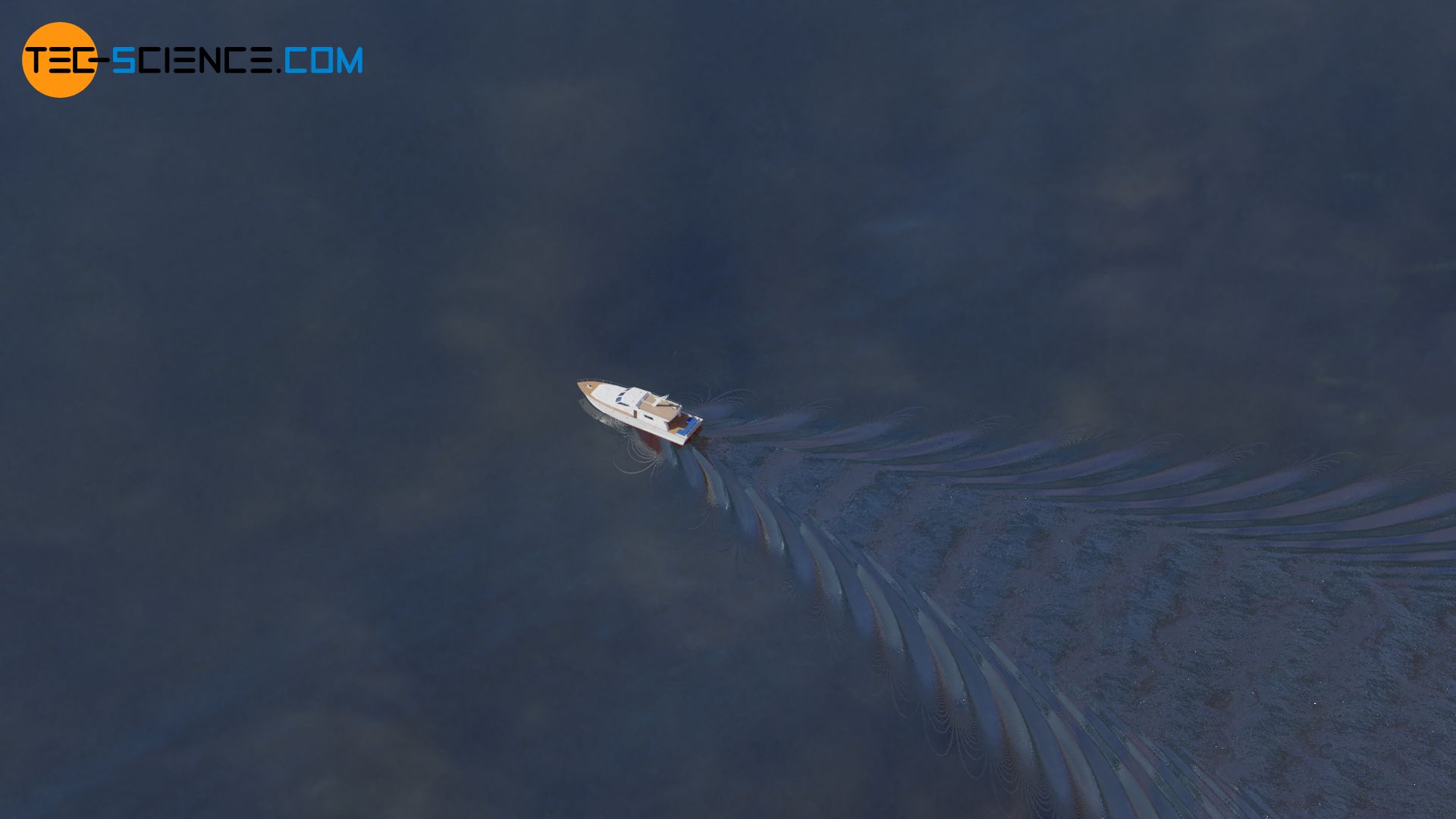
Depending on the shape of the body, the resulting adverse pressure gradient can become very large due to the decrease in speed and the boundary layer thickness increases significantly. In the case of the cylinder, the adverse pressure gradient even becomes so large that the flow is forced back against the actual flow direction. This results in a backflow area and the laminar flow detaches itself from the contour at this point. A so-called turbulent wake is formed behind the body. Such a turbulent wake can often be seen with ships in water and is also called dead water.
From a mathematical point of view, flow separation begins at that point on the surface where the flow is pushed back so strongly that the velocity gradient in the y-direction becomes zero (there is now a inflection point in the velocity profile!). According to Newton’s law of fluid friction, this means that the shear stress at the wall, the so-called wall shear stress τw, also becomes zero.
\begin{align}
&\boxed{\tau_w = \eta \cdot \left(\frac{\partial v}{\partial y}\right)_\text{wall}\overset{!}{=}0} ~~~~~\text{condition for flow separation}\\[5px]
\end{align}
The separation of the boundary layer takes place at the point where the wall shear stress becomes zero! The fluid particles follow the pressure drop which acts against the main flow direction (recirculation area).
Effect of flow separation on drag
Because after the separation point the flow no longer adheres the surface of the body, the skin friction drag is almost zero. At the same time, however, the pressure drops considerably due to the energy dissipation in the turbulent wake. This leads to a significant increase in pressure drag, which is far greater than the reduction in skin friction drag. In total, the parasitic drag (air resistance) thus increases very strongly in the event of a flow separation.
The separation of the boundary layer reduces the skin friction drag, but the pressure drag increases much more, so that the overall drag significantly!
Separation of turbulent boundary layers
The flow around a body can not only be laminar, but also turbulent at increased Reynolds numbers. In general, a laminar flow around the body should be aimed for, since this reduces flow losses to a minimum. However, this is only the case if it is ensured that no boundary layer separation occurs. If, on the other hand, this cannot be ensured, then turbulent boundary layers should be aimed for. This may sound a paradox, but a turbulent boundary layer can usually follow the profile of a body longer than a laminar flow. The reason for this is the increased transport of momentum between the fluid layers, which leads to a steeper velocity profile within the boundary layer.
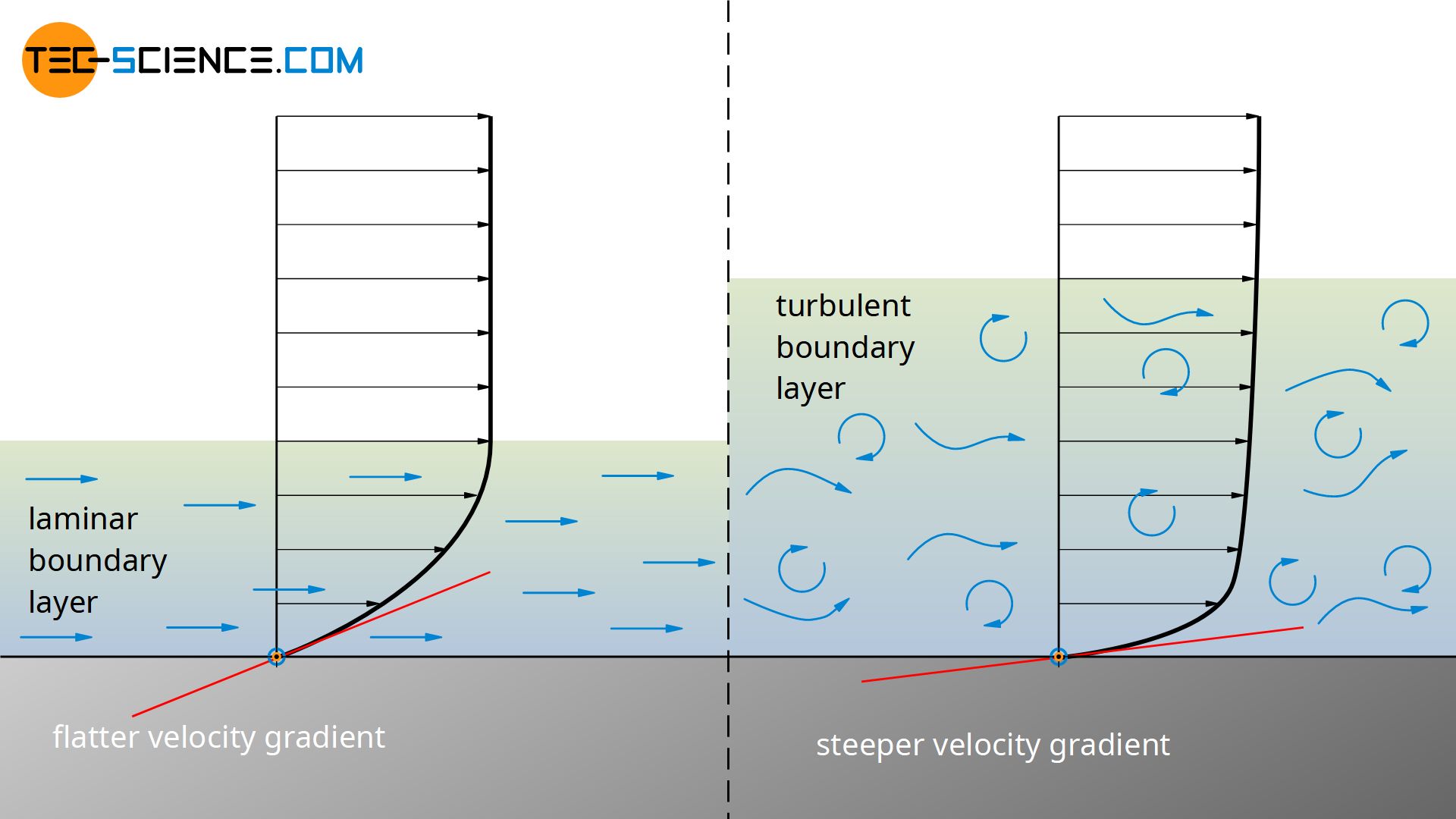
With a turbulent boundary layer, the velocity in the y-direction increases faster than with a laminar boundary layer. This means a larger velocity gradient near the wall and thus higher velocity components in the boundary layer. The resulting higher kinetic energy of the boundary layer can counteract the adverse pressure gradient more, so to speak.
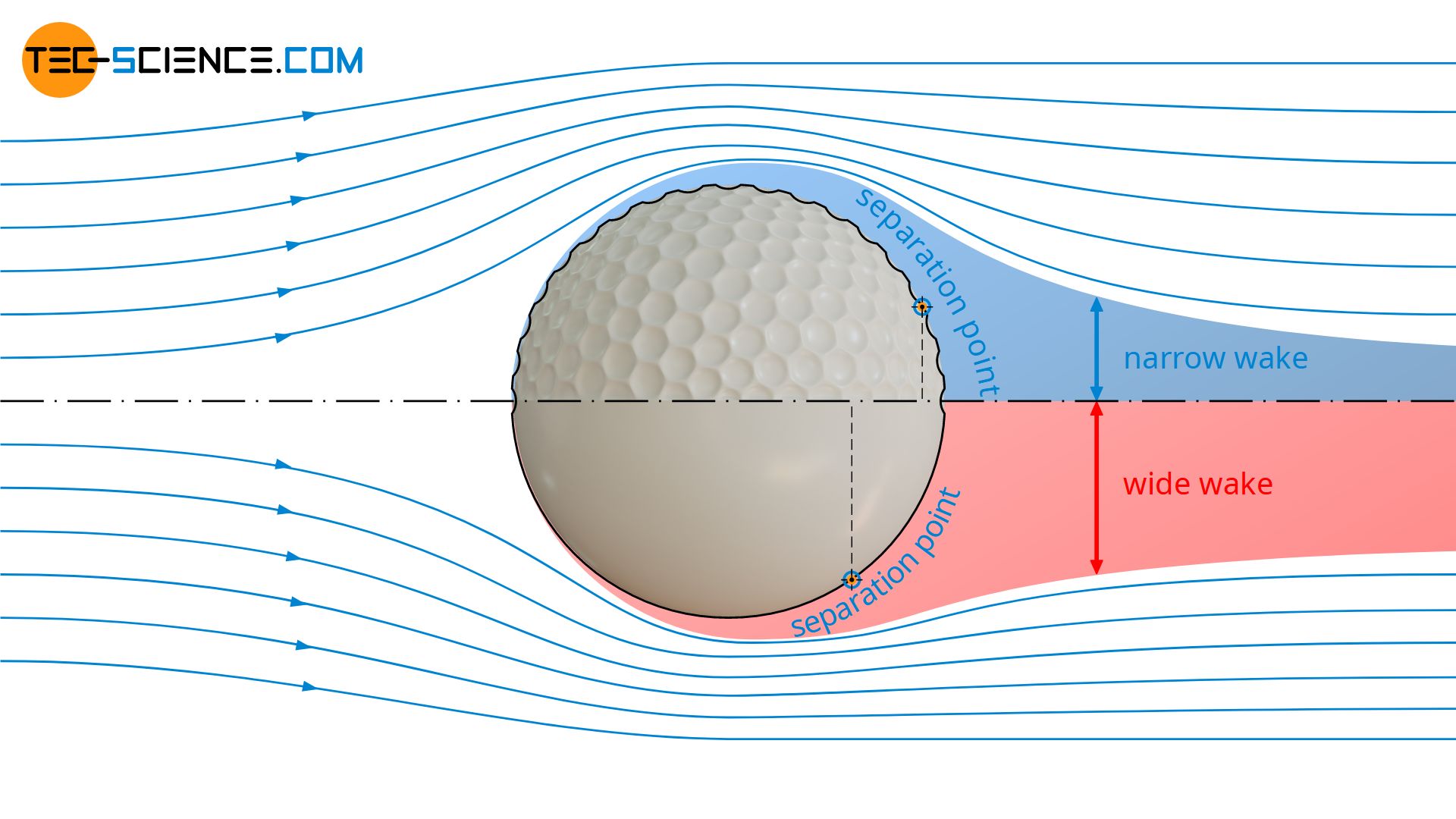
In the case of a turbulent boundary layer, the separation point thus shifts downstream. The turbulent wake becomes narrower with the shifting of the separation point. This reduces the flow losses and thus the pressure drag, which ultimately results in a reduction of the overall drag.
Turbulent boundary layers adhere longer to the surfaces of the body around which flow occurs. The (pressure) drag is significantly lower. If there is a risk of flow separation, turbulent boundary layers should be aimed for.
This fact is taken advantage of, for example, with golf balls. The dimples in the golf ball cause vortices and lead to a turbulent flow around the golf ball. The separation point shifts downstream and the drag is reduced to only a quarter, which makes the golf ball fly much further.
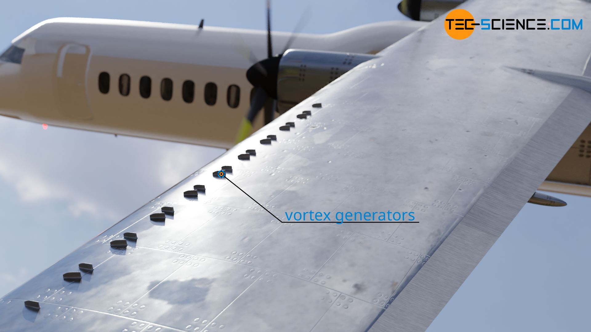
So-called turbulators (vortex generators) on the wings of aircraft act in a similar way. Often many small vanes are mounted on the wing for this purpose. These vanes create a transition from a laminar to a turbulent flow. The turbulent boundary layer, which remains longer on the wing, not only reduces drag but also the risk of hard stall. Another possibility to achieve a targeted turbulent flow around wings is the use of so-called blast turbulators. Air is blown out through small holes in the wing. This also causes the laminar flow to change into a turbulent flow.
Turbulators can also be found in racing cars. These are designed to move the flow separation as far back as possible so that the flow is still attached in the rear of the car for as long as possible.
Separation bubble
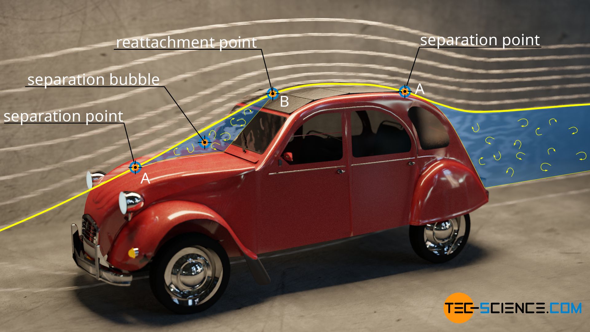
Depending on the outline of the body being flowed around, a flow that has been detached can also reattach itself to the surface. The figure below shows the laminar flow around a vehicle. At point A, the flow separates and below it forms a kind of circulating air cushion, so that the flow can reattach to the surface at point B. This area is also called the separation bubble.
A separation bubble is a recirculation area in a flow field, which is created by the separation and reattachment of the flow!
A separation bubble can also form when air flows around airfoils. The laminar flow around the wing separates at one point and reattaches itself to the wing downstream, provided the angle of attack is not too high. In the area between the laminar separation point and the point of turbulent reattachment a laminar separation bubble forms (laminar because the flow before the separation point is laminar).
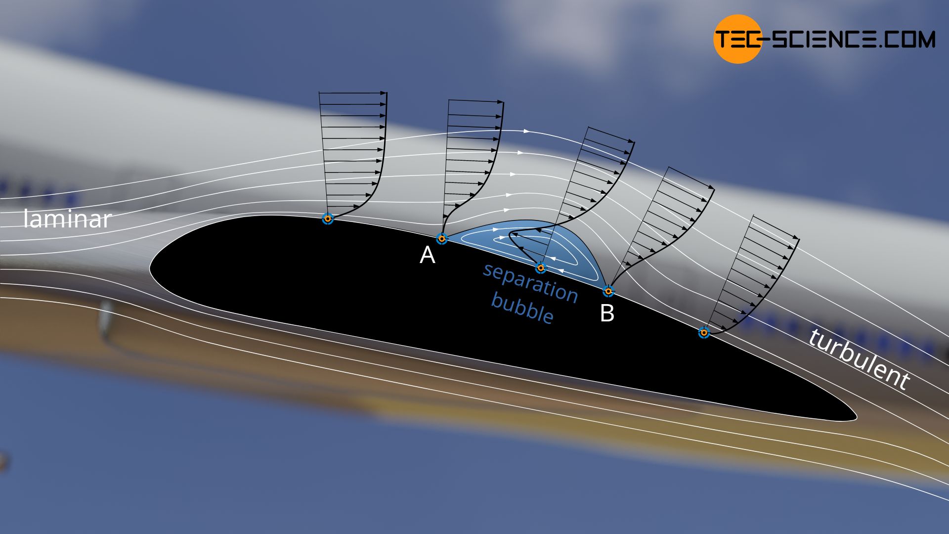
The transition from laminar separation and turbulent reattachment takes place by disturbances in the flow, which build up like waves and finally become unstable. This wave-like build-up of the flow is also known as Tollmien-Schlichting waves.
As already explained, such a separation bubble has a considerable influence on the pressure distribution over the wing. The drag rises strongly, which is why separation bubbles on airfoils should be avoided. This is where the turbulators come into play once again. They force the turbulent transition so that, ideally, the more energetic boundary layer remains connected to the wing without separation, or at least the separation point is shifted as far back as possible.
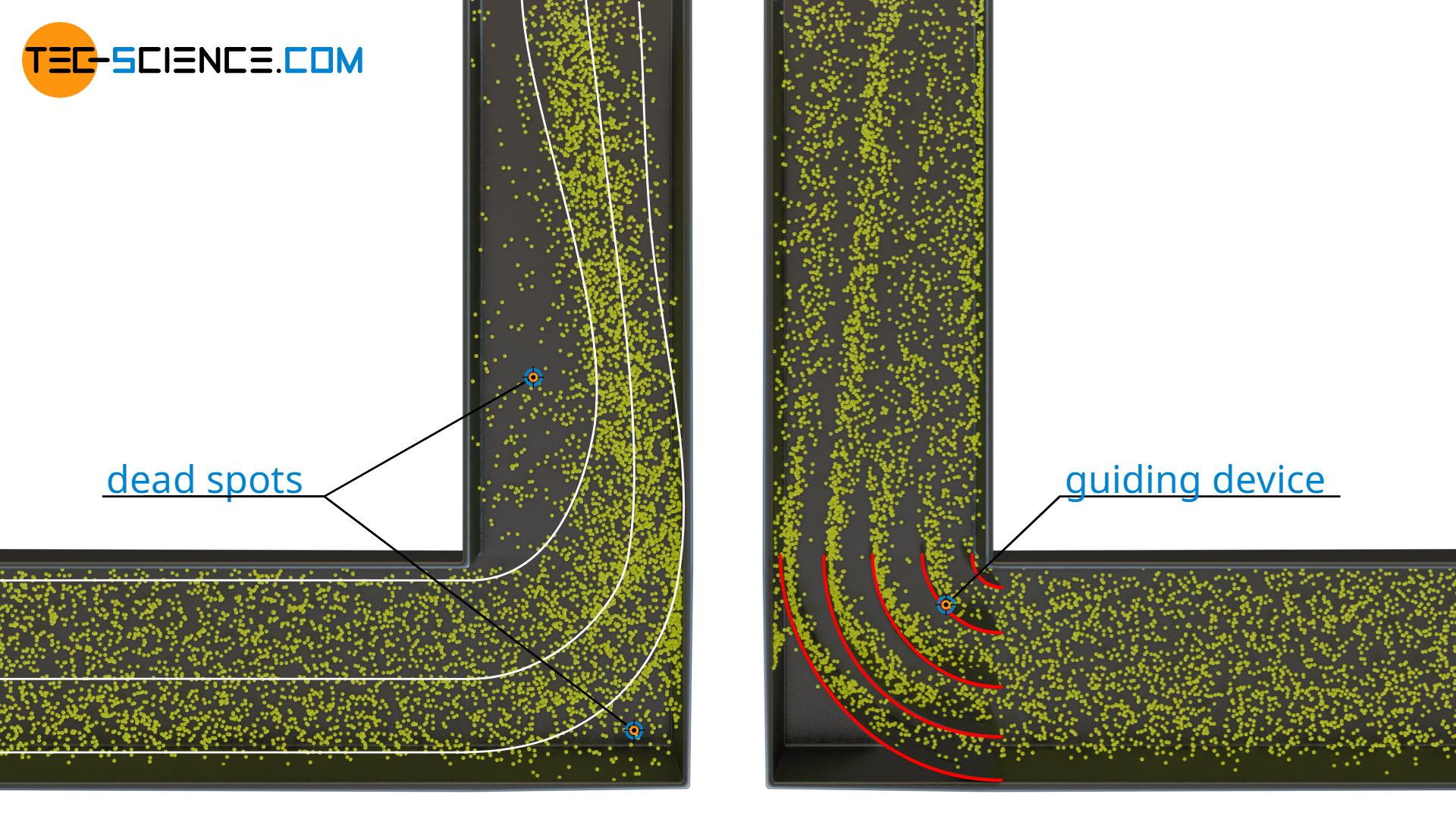
A boundary layer can also be separated from the pipe wall in the case of flows through pipes. This is the case, for example, with sharp edges around which the flow is diverted. Separation bubbles are formed at the edges. Such dead spots resulting from flow separation mean flow losses and should be avoided. This can be achieved constructively, for example, by attaching guiding devices.
Periodic flow separation (Kármán vortex street)
Whether or not a flow separation takes place depends to a decisive degree on the Reynolds number. For a cylinder, in practice no separation takes place below a Reynolds number of 4. At higher Reynolds numbers up to about 40, the boundary layer separates. In the turbulent wake, two counter-rotating vortices are formed due to the conservation of angular momentum. As the Reynolds number increases (about over 80), these vortices become unstable and start to oscillate until they finally detach periodically. The characteristic swirling wake is also known as Kármán vortex street.

The Kármán vortex street is the periodic vortex separation around a body at high Reynolds numbers!
A Kármán vortex street can be seen on satellite images, for example, when air currents flow around a mountain top. Also on Jupiter, the cloud formation around the Great Red Spot shows a Kármán vortex street.
The vortex shedding frequency f is given by the dimensionless Strouhal number Sr. It results from the characteristic length L (e.g. diameter of a cylinder) and the flow velocity v:
\begin{align}
&\boxed{Sr= \frac{f \cdot L}{v}} ~~~~~\text{Strouhal number}\\[5px]
\end{align}
The Strouhal number is usually in the range of 0.1 to 0.3, so that in many practical cases a value of 0.2 can be assumed. For such cases, the vortex shedding frequency f can be calculated with the following formula:
\begin{align}
&\boxed{f=Sr \cdot \frac{v}{L}} ~~~~~\text{often assumed: } Sr = 0.2\\[5px]
\end{align}
If, for example, a overhead power line with a diameter of 30 mm is flowed around with a wind speed of 15 m/s, this results in a vortex shedding frequency in the order of 100 Hz. Since these frequencies are in the audible range, this can be perceived as a low buzzing noise.
However, the periodic vortex shedding can sometimes bring a great danger. The structures around which the flow passes can begin to oscillate very strongly due to resonance if the vortex shedding frequency corresponds to the natural frequency of the structure. The famous collapse of the Tacoma Narrows Bridge in 1940 was attributed to such a phenomenon.
")


")
")
