In this article exercises with solutions based on the Bernoulli equation are given.
Bernoulli equation
The Bernoulli equation is based on the conservation of energy of flowing fluids. The derivation of this equation was shown in detail in the article Derivation of the Bernoulli equation. For inviscid and incompressible fluids such as liquids, this equation states that the sum of static pressure p, dynamic pressure ½⋅ϱ⋅v² and hydrostatic pressure ϱ⋅ along a streamline is constant:
\begin{align}
& \boxed{p + \frac{1}{2} \rho ~v^2 +\rho g h= \text{konstant}} ~~~\text{Bernoulli equation}\\[5px]
\end{align}
Two states on a streamline are thus linked by the following equation:
\begin{align}
& \boxed{p_1 + \frac{1}{2} \rho v_1^2 +\rho g h_1= p_2 + \frac{1}{2} \rho v_2^2 + \rho g h_2} \\[5px]
\end{align}
In the following, different exercises for the application of the Bernoulli equation will be shown.
Horizontal flow through a pipe with constricted cross-section
Water with a density of 1 g/cm³ flows through a horizontal pipe. The pipe cross-section tapers from 80 cm² to 40 cm² at a reducer. The static pressure before the reducer is 4 bar and the flow velocity is 4 m/s. The flow is incompressible and frictionless (inviscid). What static pressure is measured after the reducer?
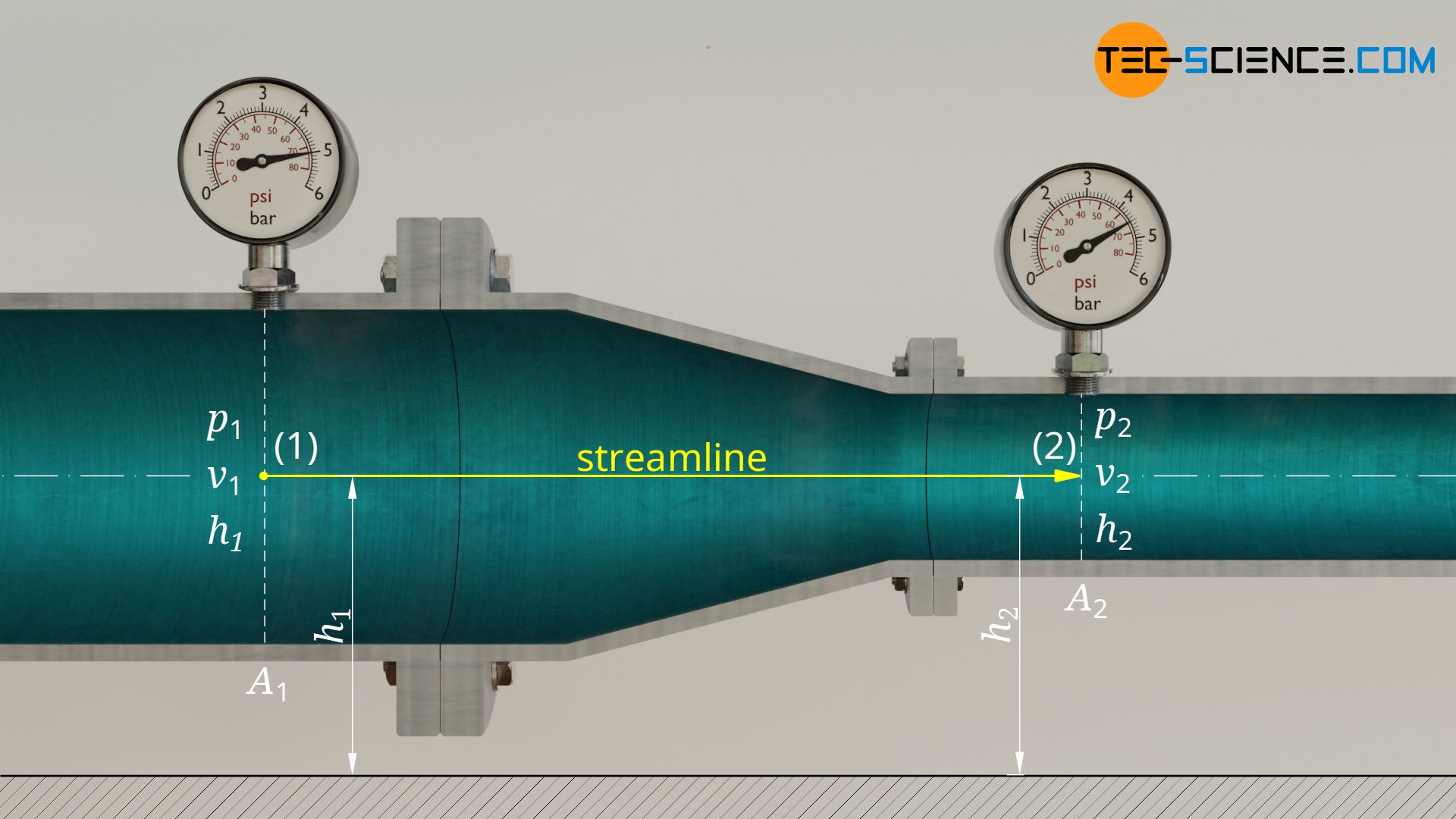
To answer this question, we look at a streamline and at a point before the reducer and after the reducer. The following state variables are known:
| state 1 (large cross-section) | state 2 (small cross-section) | |
| height | h1 = h2 | h2 = h1 |
| velocity | v1 = 4 m/s | v2 = ? |
| static pressure | p1 = 4 bar | p2 = unknown |
Note that due to the horizontal orientation of the pipe, both points considered are at the same level (h1 = h2). The Bernoulli equation is therefore simplified in that the hydrostatic pressures cancel each other out. For the static pressure p2 the following formula therefore results:
\begin{align}
\require{cancel}
&p_1 + \frac{1}{2} \rho v_1^2 + \cancel{\rho g h_1}= p_2 + \frac{1}{2} \rho v_2^2 + \cancel{\rho g h_2}\\[5px]
&p_1 + \frac{1}{2} \rho v_1^2 = p_2 + \frac{1}{2} \rho v_2^2 \\[5px]
\label{p2}
&\underline{p_2 = p_1 + \frac{1}{2} \rho v_1^2 -\frac{1}{2} \rho v_2^2} \\[5px]
\end{align}
For the calculation of the static pressure we still need the flow velocity after the constriction. We obtain this from the condition of mass conservation. Within the time Δt the fluid flows before the reducer with the velocity v1 and thus covers the distance Δs1=v1⋅Δt. The following fluid volume thus pushes through the cross-section A1:
\begin{align}
\label{1}
& \Delta V = A_1 \cdot \Delta s_1 = A_1 \cdot v_1 \cdot \Delta t \\[5px]
\end{align}
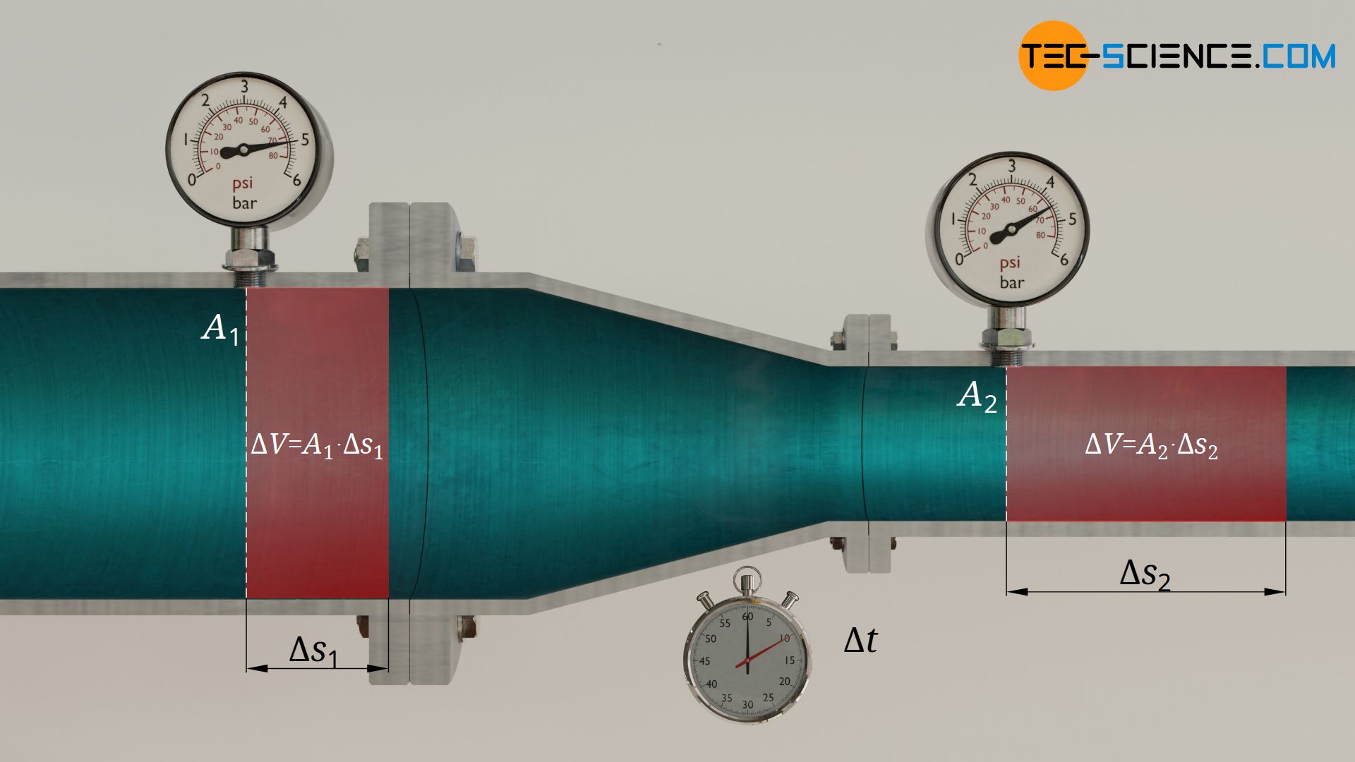
Due to the conservation of mass and the incompressibility of water, the same volume ΔV must also be pushed through the cross-section A2 within the same time Δt. Since the cross-section is smaller, the distance Δs2 of the fluid volume must be greater, which explains the higher flow velocity v2:
\begin{align}
\label{2}
& \Delta V = A_2 \cdot \Delta s_2 = A_2 \cdot v_2 \cdot \Delta t \\[5px]
\end{align}
Equating formula (\ref{1}) and (\ref{2}) and solving the resulting equation for v2 finally provides the flow velocity after the reducer:
\begin{align}
\require{cancel}
& A_2 \cdot v_2 \cdot \cancel{\Delta t} = A_1 \cdot v_1 \cdot \cancel{\Delta t} \\[5px]
& \boxed{v_2 = \frac{A_1}{A_2} \cdot v_1} = \frac{80~ \text{m²}}{40 ~\text{m²}} \cdot 4 \frac{\text{m}}{\text{s}} = \underline{\underline{8 \frac{\text{m}}{\text{s}}}} \\[5px]
\end{align}
Due to the constriction of the cross-section to only half the size, the flow speed is doubled. All known values can now be put in equation (\ref{p2}). Note that the pressure is to be used in the basic unit N/m² and the density in the unit kg/m³.
\begin{align}
&p_2 = p_1 + \frac{1}{2} \rho v_1^2 -\frac{1}{2} \rho v_2^2 \\[5px]
&p_2 = 4 \cdot 10^5 \tfrac{\text{N}}{\text{m²}} + \frac{1}{2} 1000 \tfrac{\text{kg}}{\text{m³}} ~\left(4 \tfrac{\text{m}}{\text{s}} \right)^2 – \frac{1}{2} 1000 \tfrac{\text{kg}}{\text{m³}} ~\left(8 \tfrac{\text{m}}{\text{s}} \right)^2 =3.76 \cdot 10^5 \tfrac{\text{N}}{\text{m²}} \\[5px]
&\underline{\underline{p_2 = 3.76 ~\text{bar}}}\\[5px]
\end{align}
The increase in flow velocity thus causes the static pressure to drop from 4.00 bar to 3.76 bar. This can be explained by the fact that part of the energy associated with the static pressure had to be used to accelerate the water. The increase in the kinetic energy of the water is at the expense of the static pressure. More detailed information about this phenomenon can be found in the article Venturi effect.
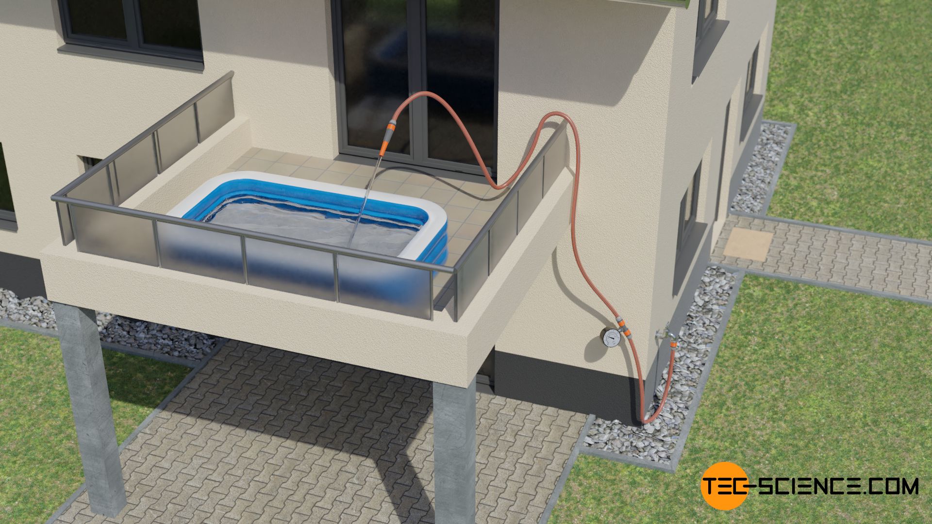
Flow in a water hose with a nozzle
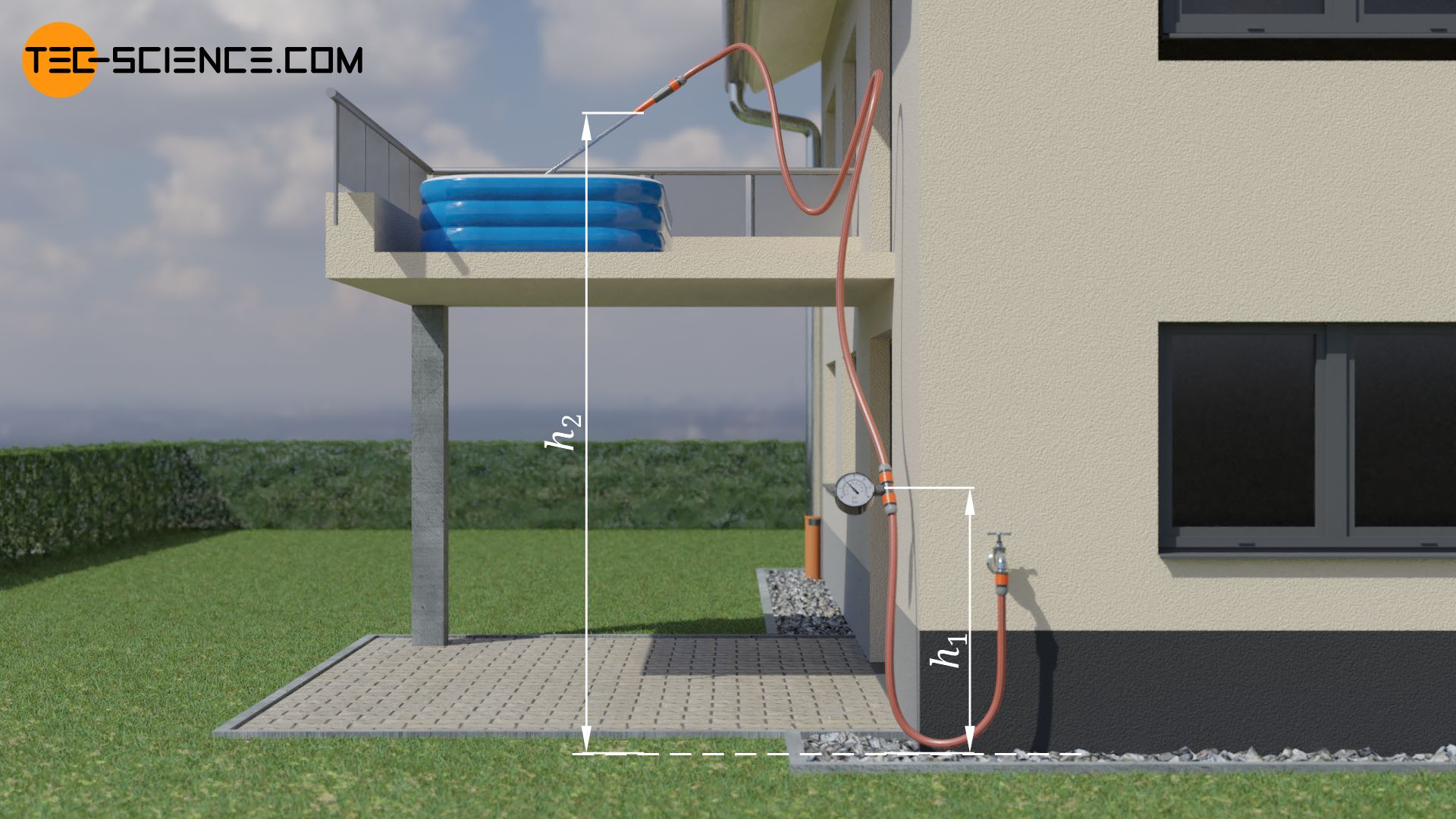
A hose with an internal cross section of 1.24 cm² is connected to a water tap. The hose leads to a height of 6 metres above ground, where the water flows out of a nozzle and is collected in a pool. The pool fills up with 30 litres per minute. One meter above the ground, a pressure gauge is attached to the hose to measure the static pressure. The gauge indicates a pressure of 2 bar. The ambient air pressure is 1 bar. The flow is incompressible and inviscid. At what speed does the water come out of the nozzle?
To answer this question we consider a streamline leading from the pressure gauge to the outlet of the nozzle. In this case, the terms for the gravitational potential energies (hydrostatic pressures) in the Bernoulli equation must be taken into account. The following variables are given:
| state 1 (pressure gauge) | state 2 (nozzle opening) | |
| height | h1 = 1 m | h2 = 6 m |
| velocity | v1 = ? | v2 = unknown |
| static pressure | p1 = 2 bar | p2 = ? |
The flow velocity v1at the measuring point can be determined via the volumetric flow rate with which the pool fills. Due to the incompressibility of the fluid, the flow rate at the pressure gauge must be the same as the flow rate that comes out of the nozzle and fills the pool. With a flow velocity v1 the following volume ΔV passes through the hose cross-section A1 within the time period Δt:
\begin{align}
&\Delta V = A_1 \cdot v_1 \cdot \Delta t\\[5px]
\end{align}
For the volumetric flow rate V* (=volume per unit time) as the quotient of the volume ΔV and time duration Δt therefore applies:
\begin{align}
&\dot V = \frac{\Delta V}{\Delta t} = A_1 \cdot v_1 \\[5px]
\end{align}
Solving this equation for the flow velocity, provides a value of about 4.03 m/s for v1. Note that the volumetric flow rate must be given in the unit m³/s:
\begin{align}
&v_1 = \frac{\dot V}{A_1} = \frac{5 \cdot 10^{-4} ~ \tfrac{\text{m³}}{\text{s}}}{1.24\cdot 10^{-4} ~\text{m²}}=\underline{\underline{4.03 \frac{\text{m}}{\text{s}}}} \\[5px]
\end{align}
What about the static pressure p2 at the outlet of the nozzle? Since the water flows unhindered into the atmosphere, only the ambient air exerts a pressure on the water jet. The ambient pressure thus imposes its static pressure on the water jet when flowing out of the nozzle:
\begin{align}
&p_2 = \underline{\underline{1~ \text{bar}}} \\[5px]
\end{align}
Now that all needed quantities are known, they can be put into the Bernoulli equation and solved for the flow velocity v2:
\begin{align}
& p_1 + \frac{1}{2} \rho v_1^2 +\rho g h_1= p_2 + \frac{1}{2} \rho v_2^2 + \rho g h_2 \\[5px]
&v_2 = \sqrt{\frac{2~(p_1-p_2)}{\rho} + 2g (h_1-h_2) + v_1^2} = \underline{\underline{10.87 \frac{\text{m}}{\text{s}}}} \\[5px]
\end{align}
So water comes out of the nozzle with a speed of 10.87 m/s.
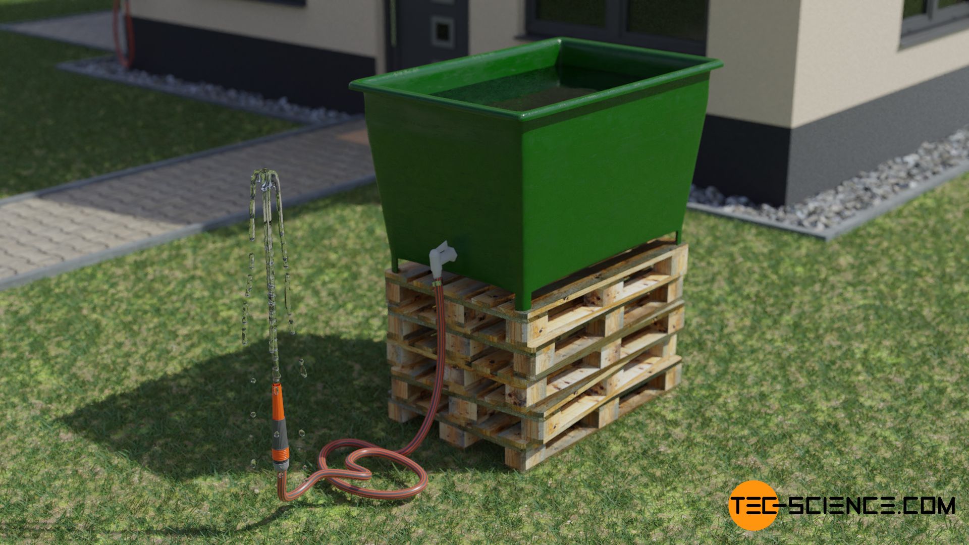
Torricelli’s law
A water tap is attached to the side of an open water tank. A hose is connected at one end to the tap. On the other end a nozzle with variable cross-section is mounted. The tank is so large that the water level (almost) does not change while the water is coming out of the nozzle. The flow is incompressible and inviscid. At what speed does the water come out of the nozzle when the water surface is at the height h above the nozzle opening?
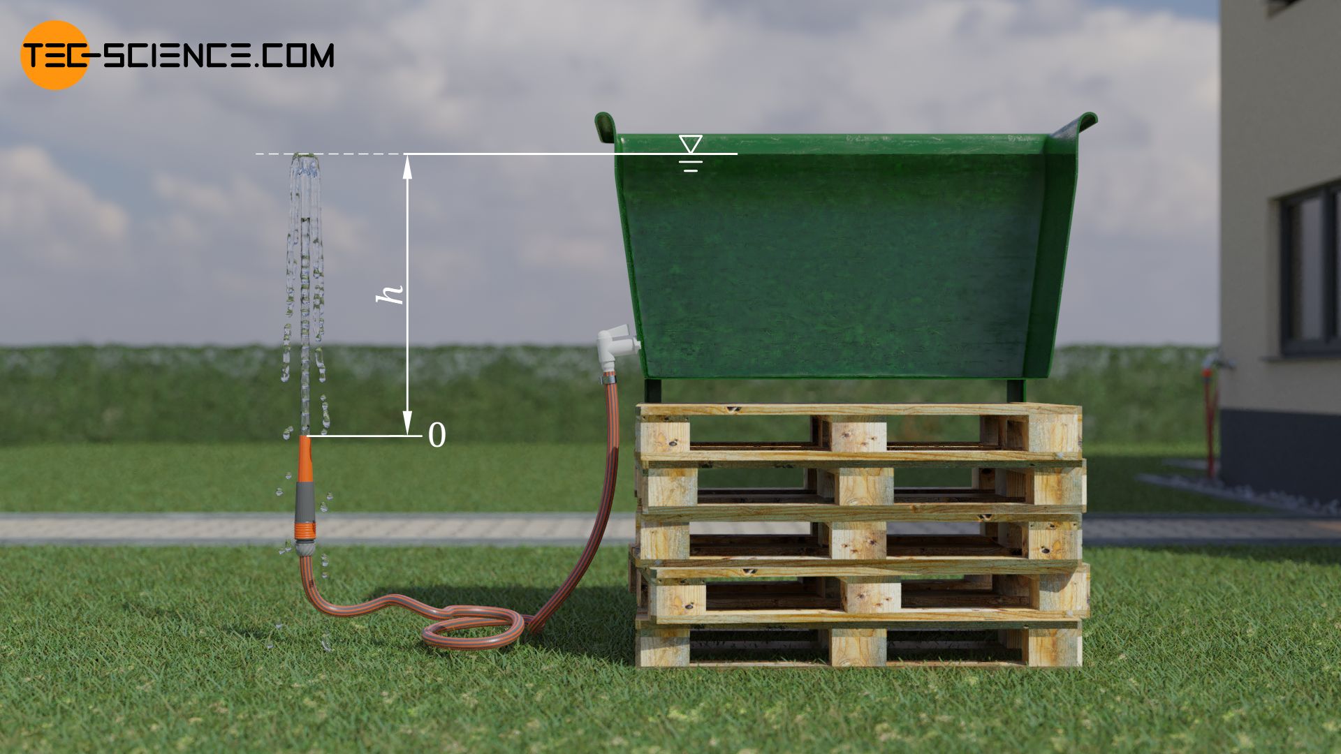
To solve this problem, we consider a streamline that leads from the water surface to the outlet of the nozzle. The reference level for the heights used to calculate the hydrostatic pressures is set at the height of the nozzle. Thus the following variables are known:
| state 1 (water level) | state 2 (nozzle opening) | |
| height | h1 = h | h2 = 0 |
| velocity | v1 ≈ 0 | v2 = unknown |
| static pressure | p1 = pamb | p2 = pu |
Note that the water level does not change noticeably when the water flows out of the nozzle. The sinking speed or the flow velocity of a fluid particle at the water surface is therefore approximately zero (v1≈0). Furthermore, the static pressure at the water surface corresponds to the ambient pressure pamb, because this pressure is applied to the water surface. The ambient pressure also acts on the water jet that comes out of the nozzle. To solve the problem, the exact value of the ambient pressure is not required because the static pressures in the Bernoulli equation cancel each other out:
\begin{align}
\require{cancel}
& p_1 + \frac{1}{2} \rho v_1^2 +\rho g h_1= p_2 + \frac{1}{2} \rho v_2^2 + \rho g h_2 \\[5px]
& \cancel{p_\text{amb} }+ \frac{1}{2} \rho \underbrace{v_1^2}_{=0} + \rho g\underbrace{h_1}_{=h}= \cancel{p_\text{amb}} + \frac{1}{2} \rho v_2^2 + \rho g \underbrace{h_2}_{=0} \\[5px]
& \cancel{\rho} g h= \frac{1}{2} \cancel{\rho} v_2^2 \\[5px]
\label{aus}
&\boxed{v_2=\sqrt{2gh}} \\[5px]
\end{align}
This result is remarkable in two ways. First, obviously only the height of water level above the nozzle is relevant for discharge velocity – the cross-section of the nozzle has no influence! Second, it can be seen that the outflow velocity corresponds exactly to the fall velocity vf if a fluid parcel were to fall from the water surface (this is also known as Torricelli’s law). The gravitational positional energy of a fluid parcel with the mass m is completely converted into kinetic energy:
\begin{align}
\require{cancel}
&\cancel{m}~g~h=\frac{1}{2}\cancel{m}~v_\text{f}^2 \\[5px]
&\boxed{v_\text{f}=\sqrt{2gh}} ~~~\text{Torricelli’s law}\\[5px]
\end{align}
From an energetic point of view it becomes clear that the outflow velocity cannot be higher than given by formula (\ref{aus}). This is because at this speed an outflowing fluid parcel can at most reach its initial height again, i.e. the height up to the water surface. If the velocity were higher, this would contradict the law of conservation of energy. Because then the fluid parcel could reach a higher height. It would then be possible to fill a higher-lying pool with no energy input.
Pressure at a certain depth of a lake
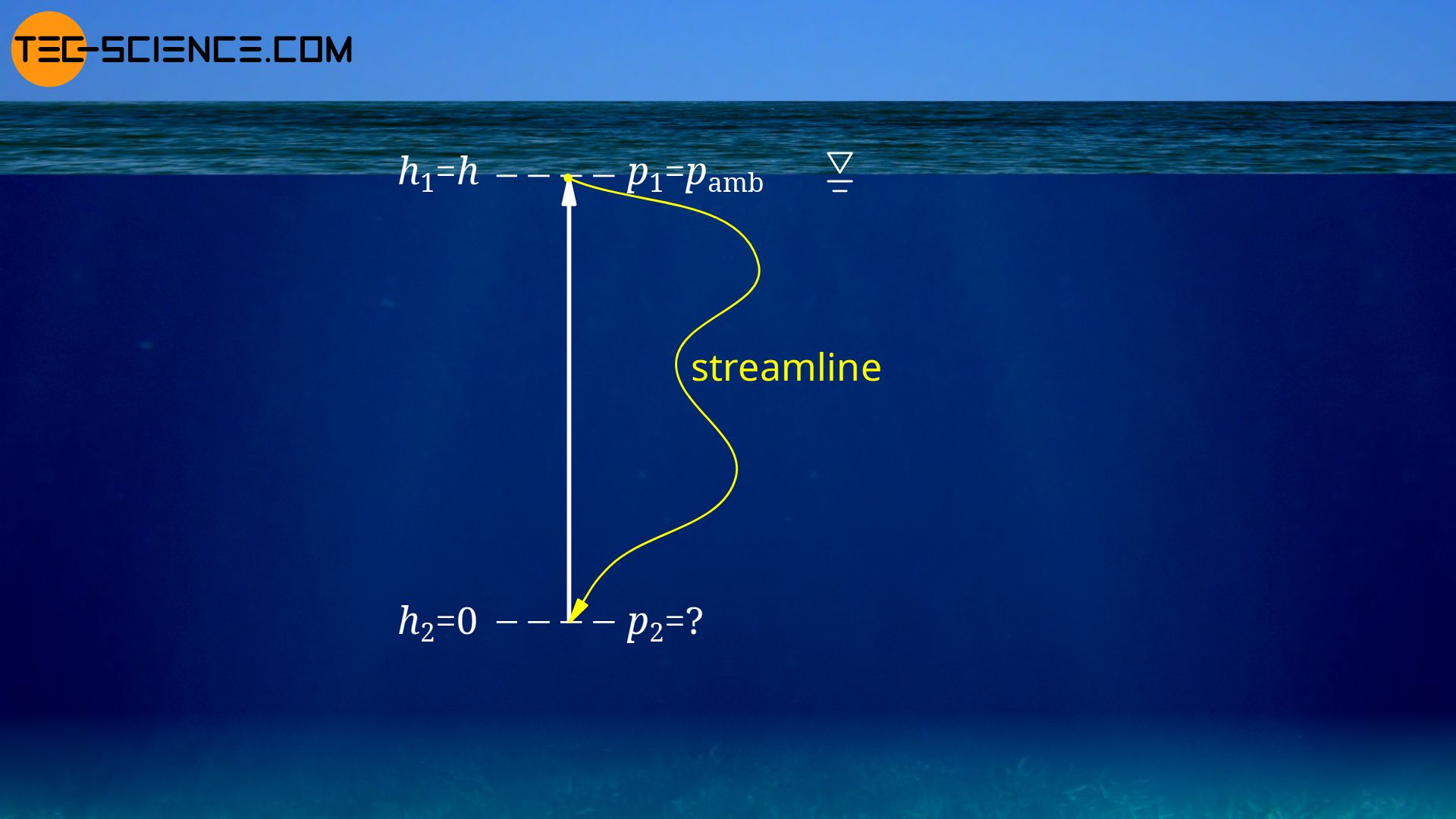
In fact, the Bernoulli equation is not only valid for a flowing fluid. The Bernoulli equation can also be applied to a fluid at rest. Let us consider a still, deep lake. What pressure exists at depth h below the water surface?
To solve this problem we consider a streamline from the surface of the water to the depth h. Note that a streamline is defined as a tangent to the velocity vectors. Since all vectors are zero for a fluid at rest, a streamline can ultimately be drawn along any path. We place the reference level for the gravitational potential energies at the considered depth. This depth is therefore assigned the height zero and the water surface the height h. The static pressure at the water surface is the ambient pressure pamb. Thus the following parameters are known:
| state 1 (water surface) | state 2 (depth) | |
| height | h1 = h | h2 = 0 |
| velocity | v1 = 0 | v2 = 0 |
| static pressure | p1 = pamb | p2 = unknown |
These parameters used in the Bernoulli equation give the following result for water pressure p2:
\begin{align}
\require{cancel}
& \underbrace{p_1}_{p_\text{amb}} + \frac{1}{2} \rho \underbrace{v_1^2}_{=0} +\rho g \underbrace{h_1}_{=h}= p_2 + \frac{1}{2} \rho \underbrace{v_2^2}_{=0} + \rho g \underbrace{h_2}_{=0} \\[5px]
&\boxed{p_2=p_\text{amb} + \rho g h} \\[5px]
\end{align}
As was to be expected, the pressure p2 at depth h corresponds to the ambient pressure pamb plus the (hydrostatic) pressure created by the water column above!
")


")
")
