In order to make the flow of fluids “visible”, one often uses the model of streamlines, pathlines (trajectories), streaklines or timelines.
Pathlines (trajectories)
Pathlines are flow paths that the fluid particles take while flowing. These flow paths are also called trajectories. Pathlines can be made visible by introducing light particles into the fluid, which follow the fluid almost without inertia. The figure below shows schematically the trajectories in a laminar and a turbulent flow.
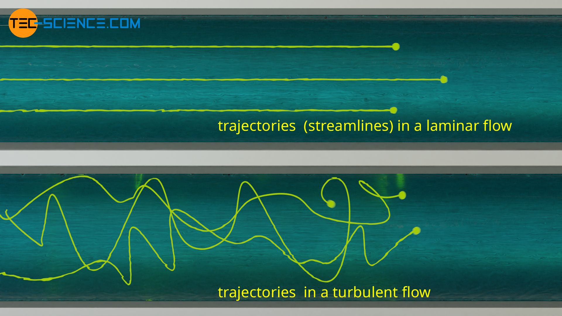

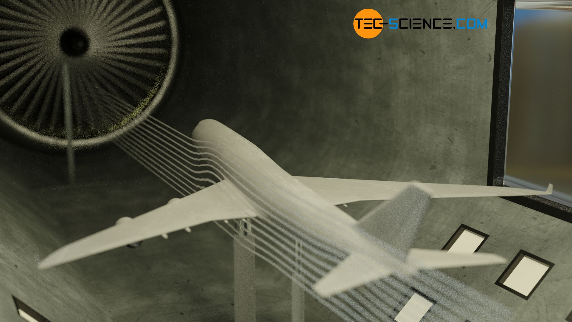
To visualize the pathlines in wind tunnels, glycerine is usually used, which is brought to evaporation. A whitish fog is formed, which is added to the flowing air. In the case of flowing liquids, dyes (e.g. ink) can be added to the fluid to make the pathlines visible.
Pathlines (trajectories) are imaginary flow paths on which massless particles would move in the fluid!
At this point, one could jump to the conclusion that the direction of flow can always be visualized with a pathline. However, this is only possible in one special case, namely when the flow does not change in time. In this case one also speaks of a steady flow.
A flow is always steady if particles that are introduced into the fluid at a certain point always move along the same path. An example of an approximately steady flow would be the flow of water in the middle of a small, shallow stream. No matter at what point in time you put a paper ship into the current (point A in the figure), it would always follow the same trajectory.
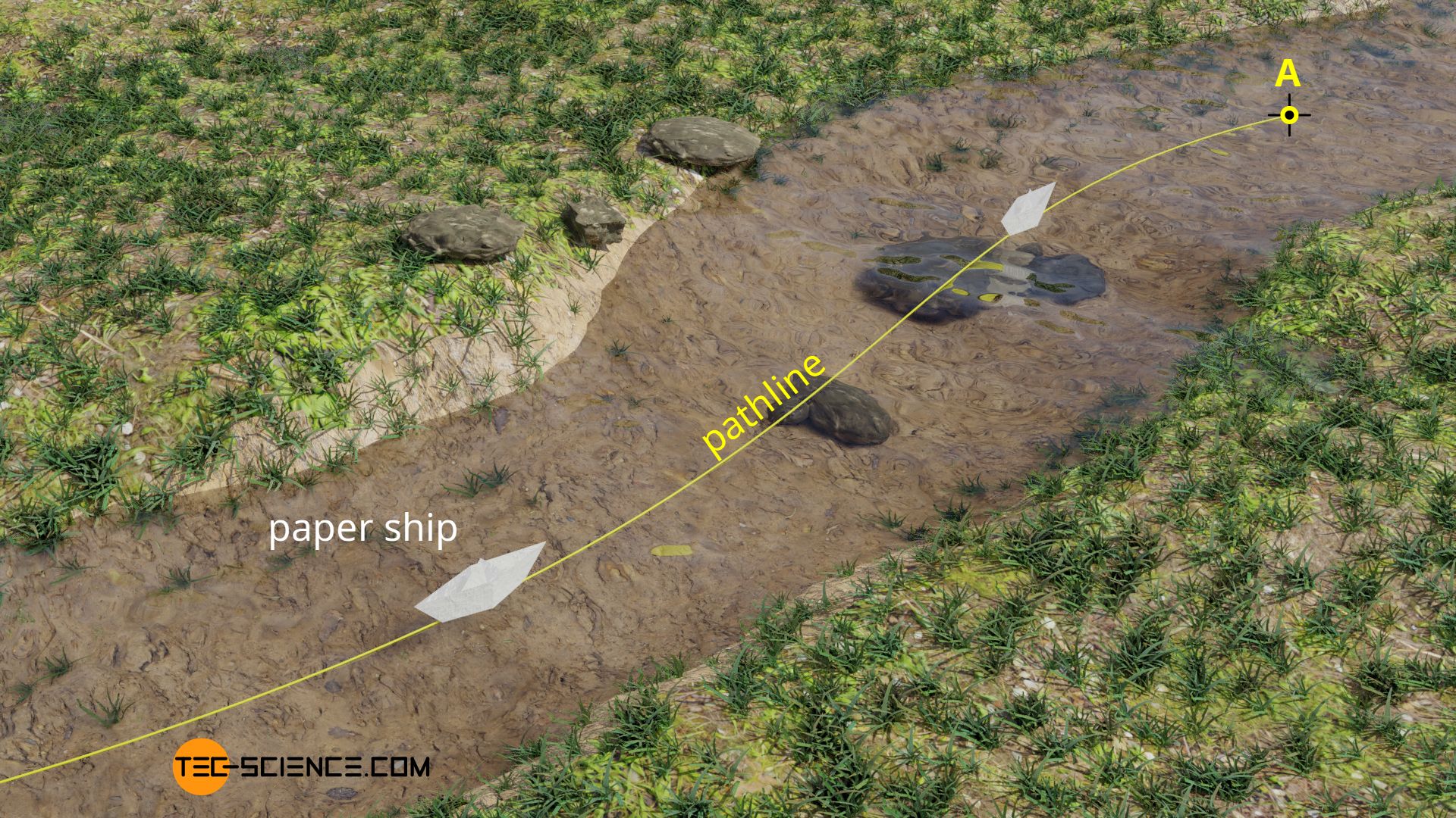
In a steady flow, the speed of the flow remains constant in time at every point, i.e. starting from a certain point, a fluid particle always follows the same path!
If, on the other hand, a flow changes in time, a particle introduced later in the fluid at a certain point would move along a different pathline. In this case one speaks of a unsteady flow. A very good example of a unsteady flow is wind on a stormy day. If you release two feathers at different times at the same point (point A in the figure), they will follow different pathlines, because the velocity of the flow changes permanently in magnitude and direction.
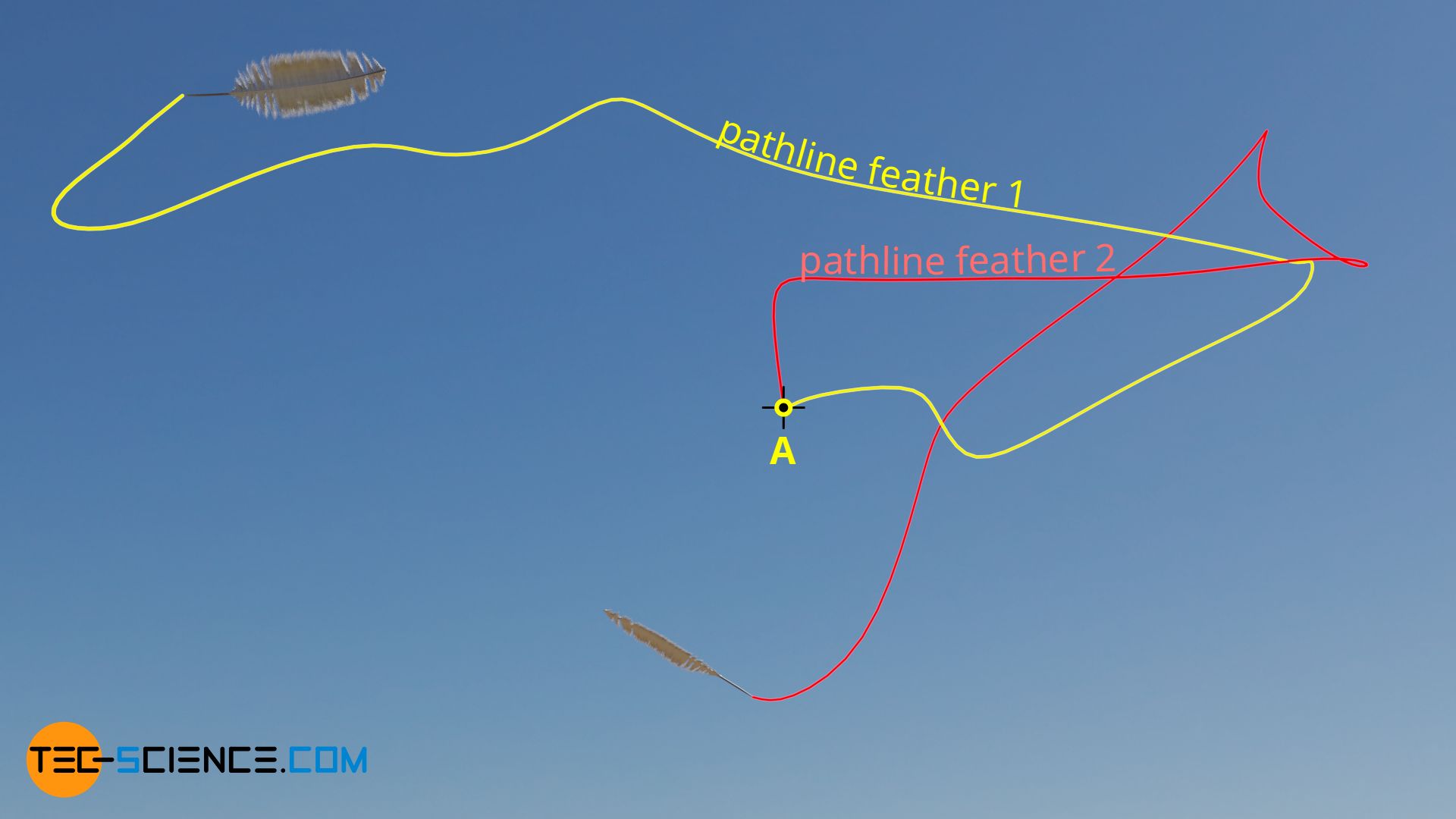
In a unsteady flow, the velocity of the flow changes in magnitude and direction, i.e. based on a certain point, a fluid particle always follows different pathlines!
Streamlines
A closer look shows that only for a steady case a pathline can also represent the (constant) flow velocity. In this case, the direction of the flow corresponds to the tangent to the pathline. Such a line is also referred to as a streamline. Several parallel streamlines in the shape of a tube form a so-called stream tube.
Streamlines are imaginary lines that represent the direction of the flowing fluid at a certain point in time (the direction of flow velocity is tangential to the streamline). Only in a steady flow are streamlines identical to pathlines.
Difference between streamline and pathline
In the case of an unsteady flow, it is basically no longer possible to draw conclusions about the velocity of the flow at a certain point in time from a given pathline. The figure below shows once again the trajectories of the two feathers, which are released at different times.
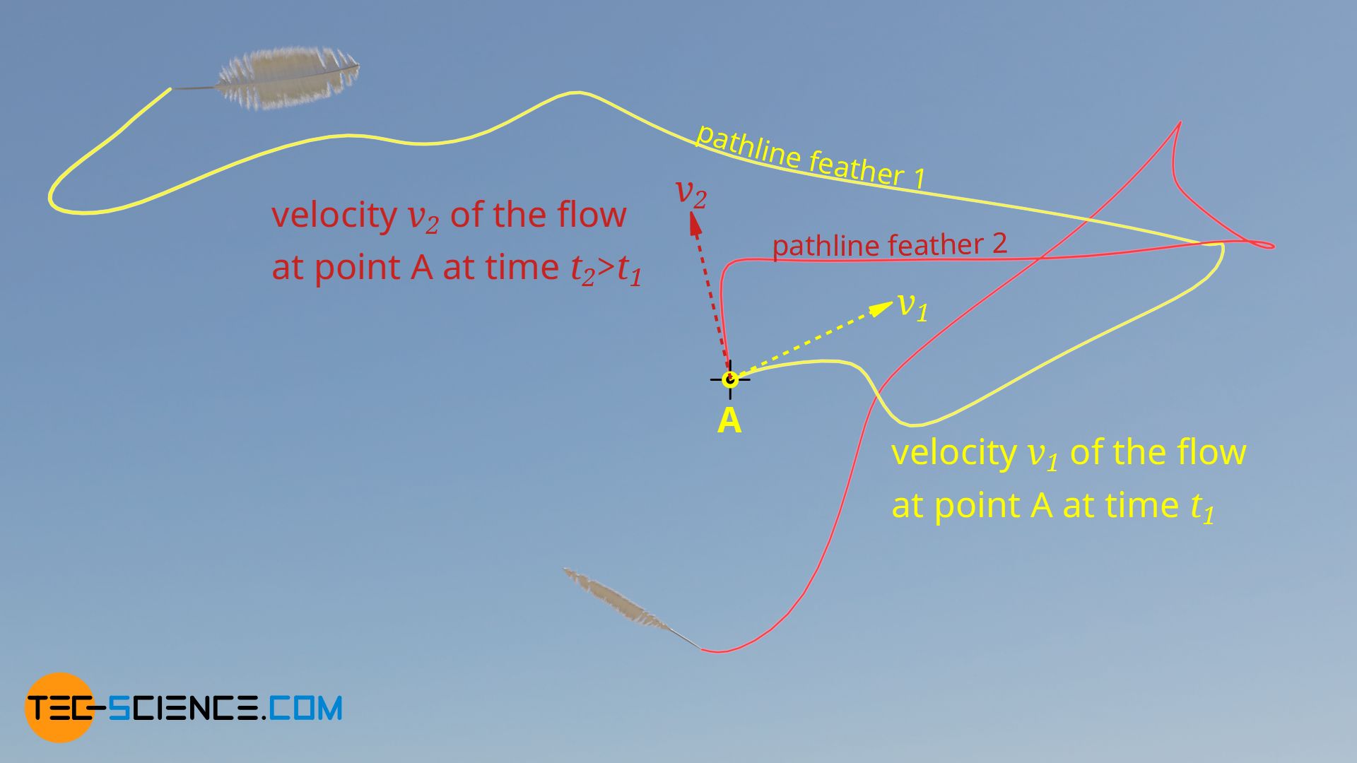
While at a point in time t1 the velocity vector of the flow at point A points to the upper right (v1) when feather 1 is released, at a later point in time t2 – when feather 2 is released – the velocity vector points to the upper left (v2). At this point in time t2 the flow velocity is no longer tangential to the pathline of feather 1. Pathlines do not therefore represent the velocity field of an unsteady flow. Pathlines and streamlines are therefore different.
In the case of turbulent air, the velocity field could be made visible, for example, by many small flags. These flags show the current direction of flow at a certain point in time for their respective location. If one then draws lines that are parallel to the flags (direction of velocity), one would obtain streamlines in this way.

In practice, the determination of the streamlines for unsteady flows is therefore connected with a relatively large effort. In many practical cases, however, one has to deal with steady flows anyway, so that in these cases no distinction between pathlines and streamlines is necessary. With the help of the easy to obtain trajectories (e.g. with the mentioned fog or a colored liquid) one can easily get a picture of the velocity field of the steady flow.
Streamline density as a measure for the magnitude of the flow velocity
Streamlines illustrate velocity fields in the same way that field lines illustrate force fields. Accordingly, streamline images can also be interpreted against a background of streamline density. The figure below shows the streamlines in a reducing pipe.
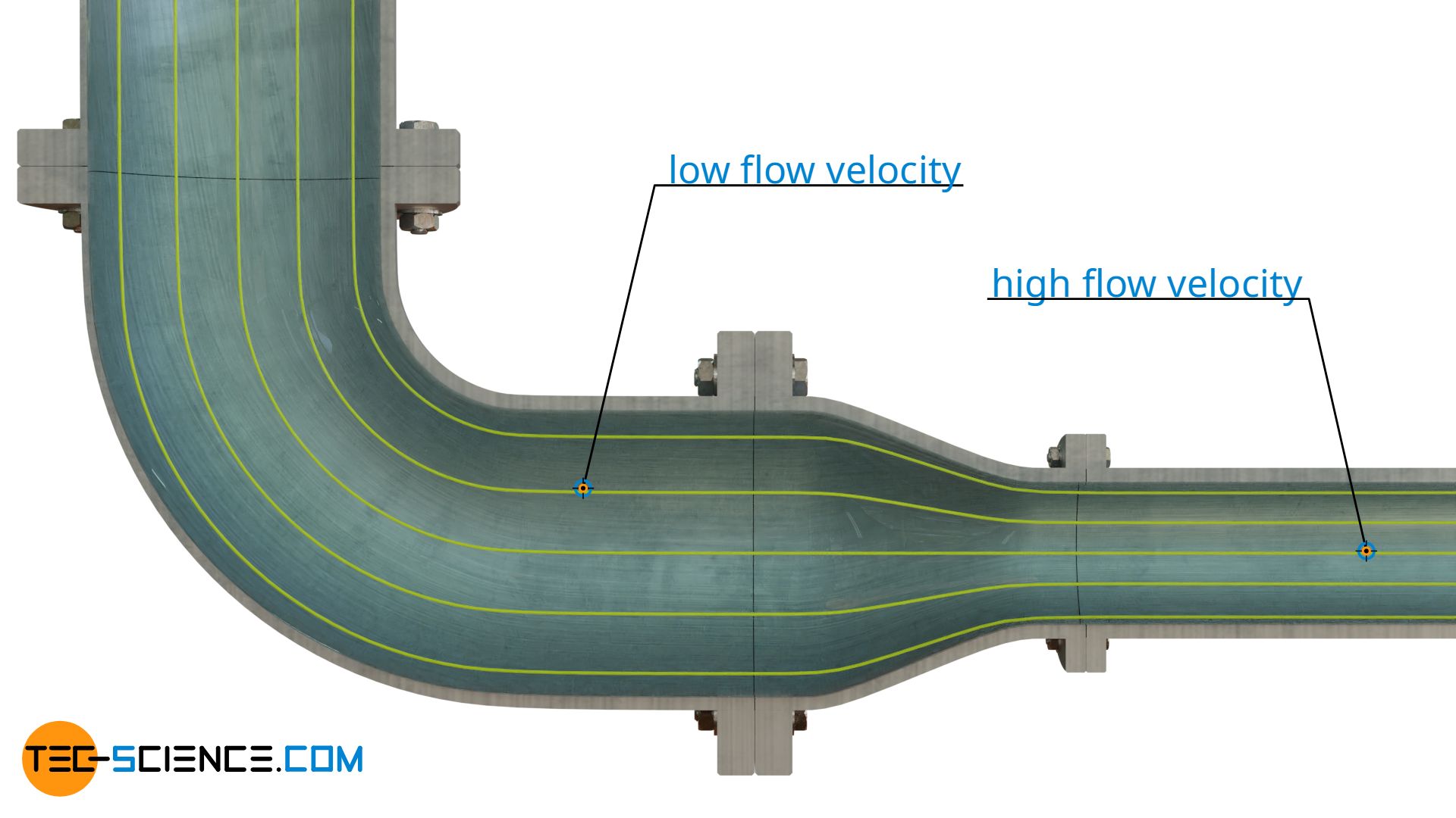
Due to the smaller cross-section, the fluid will pass through there with higher speed than through the section with the larger cross-section, because the same mass must still be moved through both sections within the same time (mass conservation). By this example one can see, that density of streamlines thus is a measure for the speed of flow. This applies at least to subsonic flows. In supersonic flows, an increase in speed results in a decrease in streamline density.
With subsonic flows a narrowing of the streamlines (high streamline density) means an increase in flow speed and with supersonic flows a decrease in flow speed!
Note, that streamlines do not intersect. At one point the flow velocity is always clearly defined and cannot have two directions, as would be the case at an intersection.
Streamlines do not intersect!
Pressure gradient perpendicular to curved streamlines
The figure below shows that fluid particles move along curved pathlines (streamlines) when flowing through the pipe angle. However, due to inertia, a fluid particle always tries to move in a straight line. The curved path must therefore be forced by applying a certain centripetal force. This is done by an outward increasing pressure perpendicular to the streamlines. The fluid particles are thus pressed inwards by the greater pressure on the outside and thus move at curved tracks. The increase of pressure perpendicular to direction of flow is all the greater …
- the higher the flow speed is and
- the smaller the radius of curvature is and
- the higher the density of the fluid is.
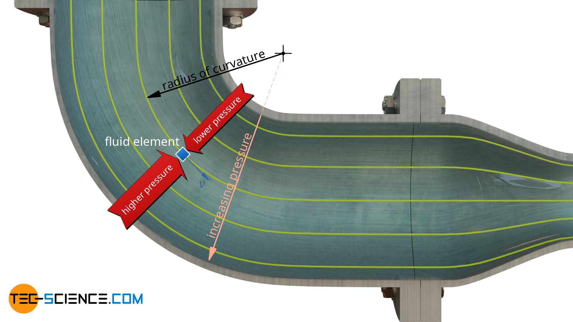
Vice versa this means, the less strongly the streamlines are curved, the lower the pressure gradient perpendicular to the flow is. For parallel streamlines, the radius of curvature is ultimately infinitely large and thus the pressure gradient is infinitely small. This means that for parallel streamlines there is no change in pressure perpendicular to the flow direction. After all, no centripetal force must be applied to streamlines running in a straight line. More information about streamlines and a derivation of the pressure gradient for curved streamlines can be found in the article Equation of motion of a fluid on a streamline.
At curved streamlines, pressure at right angles to streamlines increases from inside towards outside. At straight streamlines no pressure gradient perpendicular to the flow direction exists!
Pressure measurements in pipes should therefore not be carried out on curved pipe sections. Depending on the position of the measuring point on the circumference (different radii of curvature), different measurement results would be obtained. Pressure measurements therefore only make sense on straight sections where the pressure is constant over the cross-sectional area of the flow and is therefore independent of the position of the measuring point on the pipe circumference.
Streaklines
It has already been explained that in unsteady or turbulent flows, particles introduced one after the other in time (at the same place) follow different pathlines. If at a certain point in time all the particles introduced one after the other are joined together, a so-called streakline is formed.
A streakline is the connecting line of particles introduced one after another in thought into a flow!
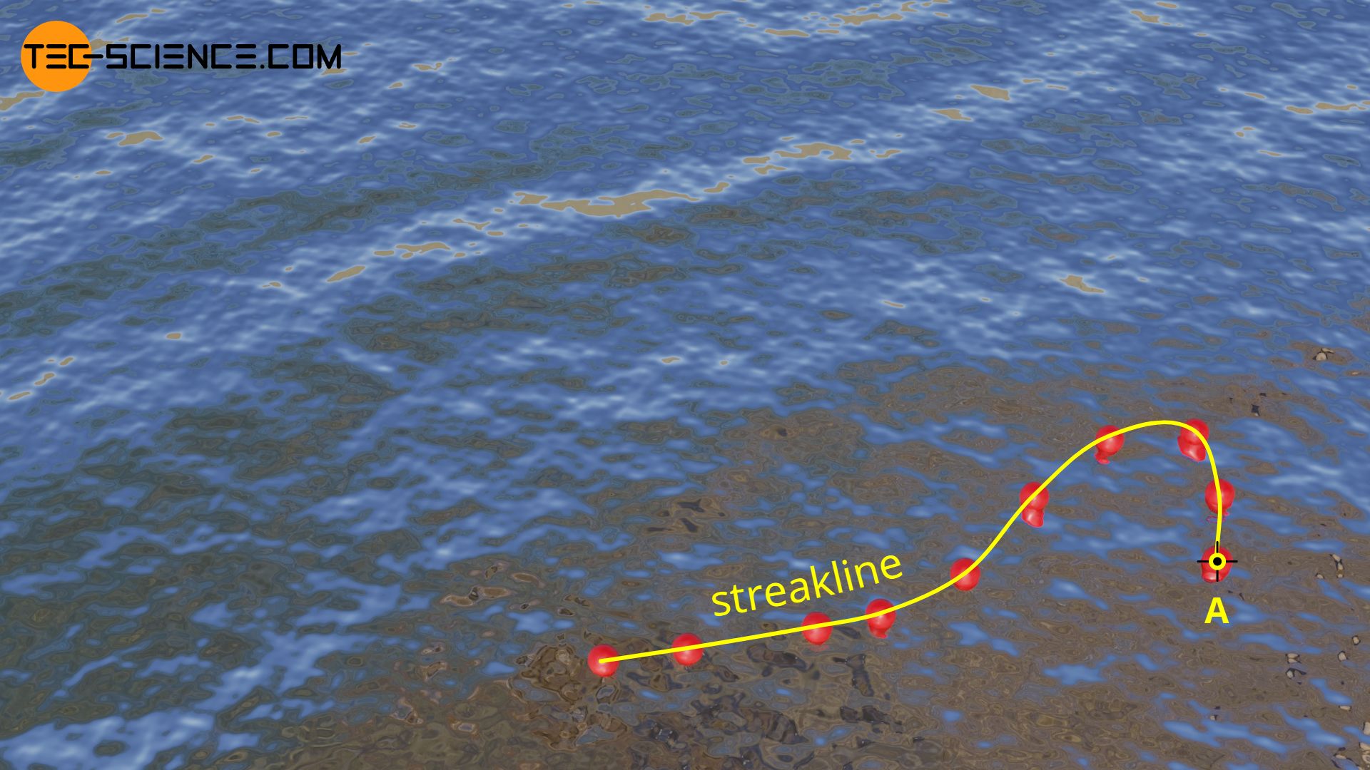
In the case of a unsteady streaming waters, one can imagine the streaklines as follows. For this purpose, imagine balls of plastic, which are connected to each other by an imaginary string. These balls are now brought into the water at the same position one after the other (point A in the upper figure). The imaginary string then describes the streakline. In the case of a steady flow, streaklines are in turn identical to pathlines and streamlines.
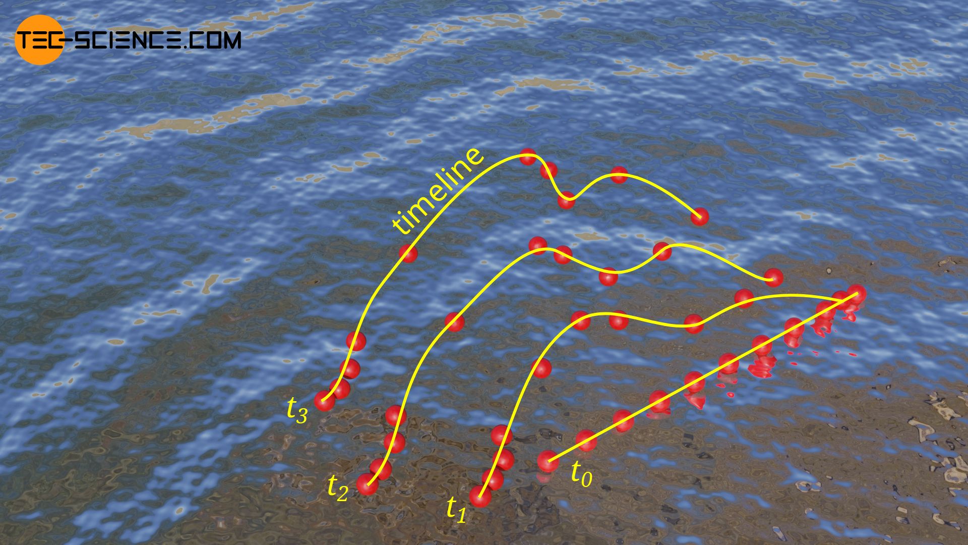
Timelines
The temporal behavior of a flow (especially a turbulent flow) can also be made visible with so-called timelines. A timeline can be used to visualize particles in a fluid, which are not introduced one after the other at the same place, but at different places at the same time. The connecting line of these introduced particles determines the timeline at any further point in time.
")


")
")
