Torricelli’s law (Torricelli’s theorem) states that the discharge velocity of a liquid equals a free fall of the liquid from the liquid surface to the opening of the tank.
Outflow speed (discharge velocity)
Derivation
It is relatively easy to determine the speed at which a liquid in a vessel flows out through an opening due to the hydrostatic pressure. For this we consider a container filled with water. Near the bottom, there is an orifice pointing upwards. The water thus flows upwards at a certain speed, which we would like to know. In this case, the following question must be answered: At what maximum velocity can the water flow out at all, so that the law of conservation of energy is not violated?
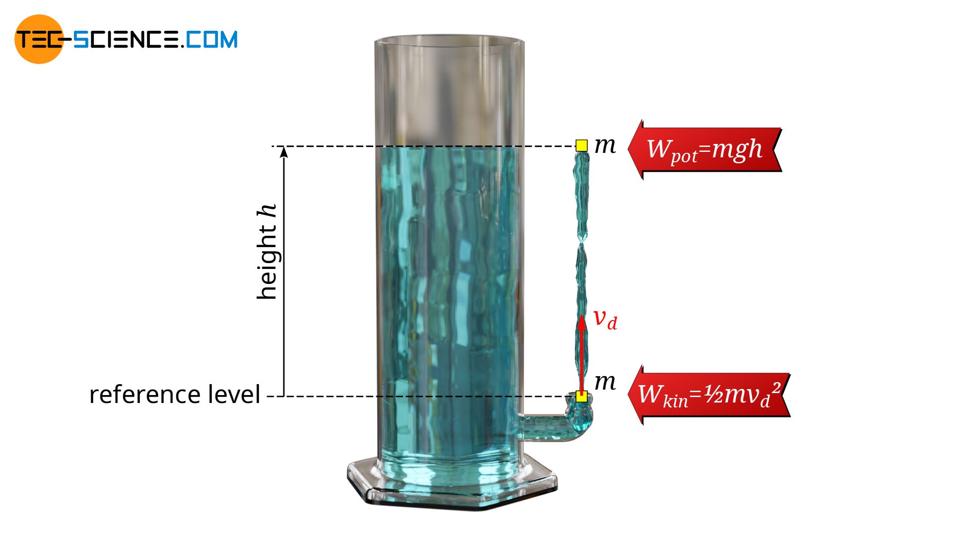
The answer is: The water can flow out so strongly that the jet is not higher than the water surface (neglecting friction). If this were the case, a higher vessel could be filled with this jet. One could now fill another, even higher vessel. The water would practically move upwards by itself. But this would contradict the law of conservation of energy. Conversely, energy would be destroyed if water only reached a lower height than the original water surface.
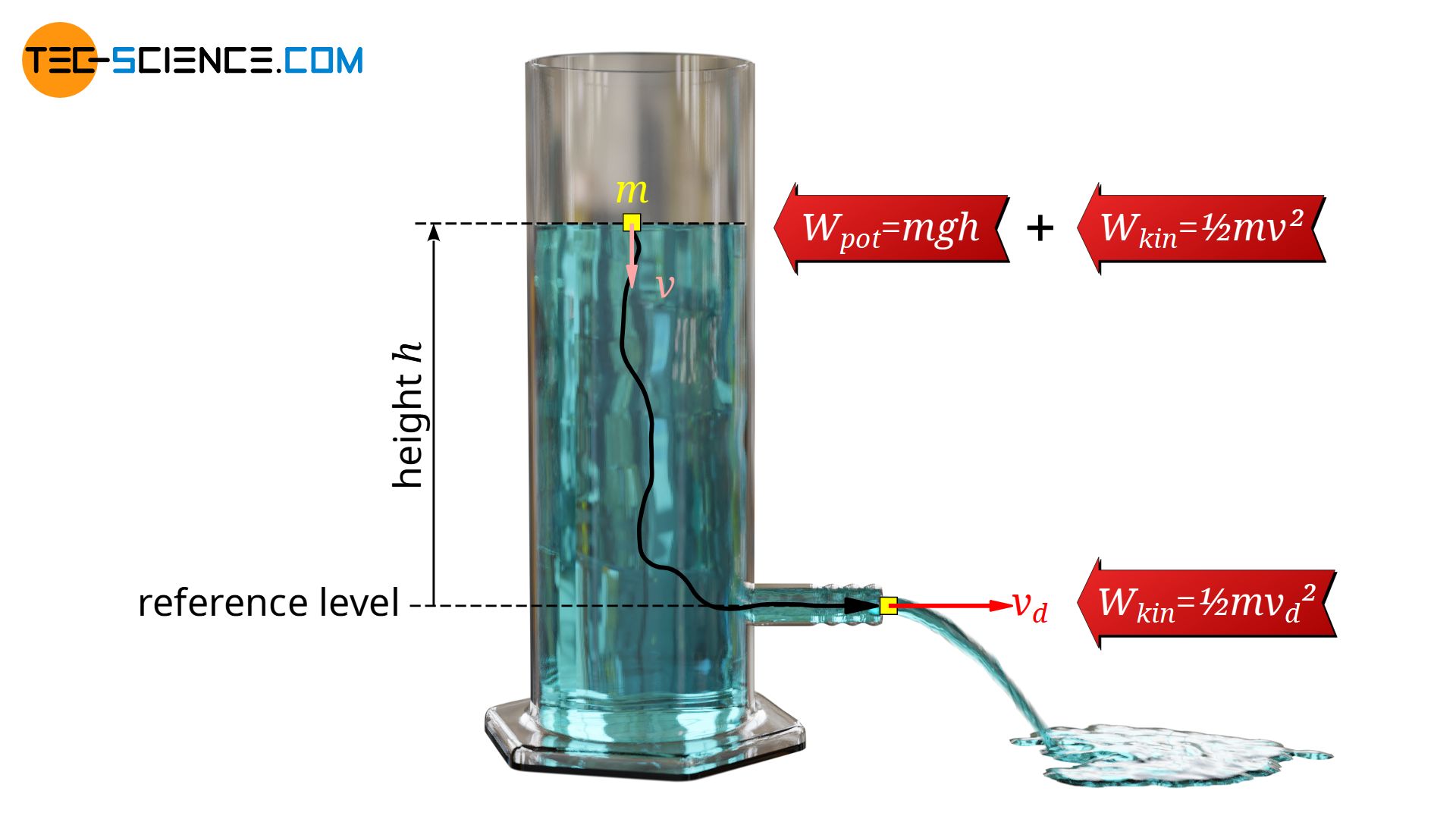
From an energetic point of view it is therefore clear that the kinetic energy of a water particle (Wkin=½⋅m⋅vd2) can be converted at most completely into potential energy (Wpot=m⋅g⋅h). The height h corresponds to the height of the water surface above the opening (or the depth of the opening below the water surface) and m to the mass of a water particle. Thus the velocity of a fluid flowing out from an orifice can be calculated as follows:
\begin{align}
\require{cancel}
W_{L} &= W_{kin} \\[5px]
\bcancel{m} \cdot g \cdot h &= \frac{1}{2} \cdot \bcancel{m} \cdot v_d^2 \\[5px]
\end{align}
\begin{align}
\label{tl}
&\boxed{v_d=\sqrt{2gh}} \\[5px]
\end{align}
Note that this formula is only valid under the condition that the liquid can flow out freely. If a counter pressure builds up during the outflow, this formula is no longer valid because the liquid is then prevented from outflowing. This will be the case, for example, if the outflowing liquid is led through a hose into a closed container. As the liquid level in the closed container rises, the air inside it is compressed and a counter pressure builds up. The outflow speed (discharge velocity) is then lower than equation (\ref{tl}) suggests.
Interpretation of the formula
As can be seen from the equation, the speed at which a fluid flows out of a container with a hole only depends on the difference in height between the opening and the surface of the liquid. It is also irrelevant to the discharge speed (which is directly measured at the opening) whether the opening is pointing upwards, downwards or sideways.
Equation (\ref{tl}) also shows that the discharge velocity does not depend on the density of the liquid! Neglecting friction, it doesn’t matter which liquid is in the container. This seems paradoxical at first, since the hydrostatic pressure in a denser liquid is also greater. As a result, one might think that a denser liquid is then pressed through the opening at a greater pressure and therefore reaches a higher height. The fact that the pressure is higher is completely correct, but this is exactly how the “heavier” liquid reaches the same height!
This interpretation also makes clear that equation (\ref{tl}) is only valid if the sink rate of the liquid surface is negligibly small compared to the discharge velocity. Otherwise a particle at the water surface would not only have positional energy but also kinetic energy. This should then also be taken into account in the energy equation (more on this later).
Torricelli’s Theorem
The derivation of the discharge speed, however, allows another interesting interpretation. For this we do not consider the outflow process outside the vessel, but the processes inside. Water flows from the surface downwards and then out of the opening. So we consider a small amount of liquid of mass m at the height h above the opening (reference level). This mass can therefore be assigned the positional energy Wpot=m⋅g⋅h. On the way to the opening, this positional energy is converted into kinetic energy. At the opening, the kinetic energy is completely converted into kinetic energy Wkin=½⋅m⋅vd2. Equating the energies yields the same result as equation (\ref{tl}).
In the present approach, it is obviously assumed that a water mass considered at the surface performs a free fall to the opening. Even if the water particles actually do not free fall, this is still the same from an energetic point of view. Because with every outflow of a certain mass from the opening, water must sink down to the same extent, i.e. fall down.
Such a continuous process can also be imagined as a discontinuous process. Imagine closing the opening with a finger. For a short time the outlet is opened, so that suddenly a small amount of water flows out immediately. This causes the water level to drop abruptly. It falls down for a short distance in free fall. One can therefore imagine the sinking of the liquid surface when the water flows out of the opening as many small free falls.
The imaginary free fall of a quantity of liquid as it flows out of an orifice is also called Torricelli’s law oder Torricelli’s theorem.
Communicating vessels
Equation (\ref{tl}) can also be used to explain why a common liquid level results when differently filled vessels are connected to each other. This is also known as the principle of communicating vessels.
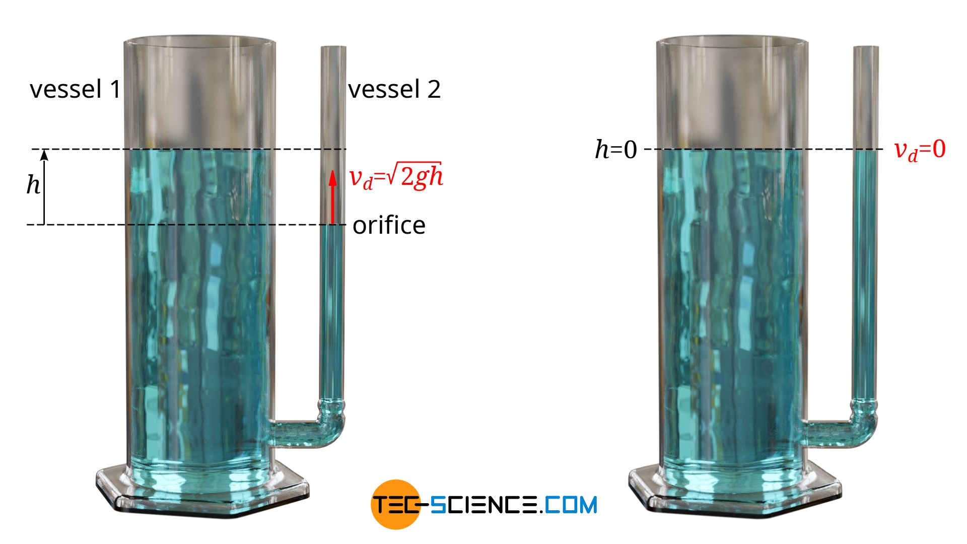
The vessel with the lower liquid level can be regarded as the opening of the other vessel. The water flows out through this opening at the velocity v according to the equation (\ref{tl}). So as long as there is a difference in height in the water level, water flows upwards. Only when there is no more difference in the water levels does the water stop flowing out, because the discharge velocity is then zero. In this case, identical water levels have been reached.
Drainage time (discharge time)
When a liquid drains out of a tank, the question often arises as to how long it will take to completely empty the tank. Such a case could be, for example, when a bathtub filled with water is emptied. In the following, we would therefore like to determine such discharge times for simple geometric containers. To simplify, we assume that the height of the outlet opening (orifice diameter) is small compared to the filling level of the tank.
How quickly a container is drained depends, among other things, on how quickly the liquid flows out. After all, a high outflow velocity means a lot of outflowing mass per time. According to the equation (\ref{tl}), the outflow velocity depends on the head h (depth of flow). In the beginning, when the liquid level is high, a lot of liquid flows out of the tank per unit time. Thus, the level drops relatively quickly at first. As the level drops, however, the discharge velocity decreases more and more and the tank drains more slowly.
Significance for everyday life and technology
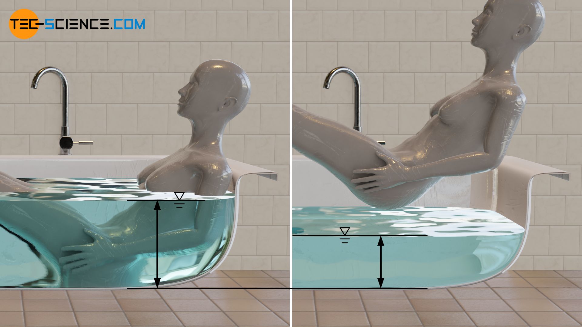
An important conclusion can already be drawn at this point. The higher the liquid level, the faster a tank can be emptied. This is also the reason why a bathtub drains faster if you lie in it. Because thereby one displaces the surrounding water and the filling level is longer on a higher level than if one gets out of the bathtub.
In technical terms, this means that tanks that have to drain very quickly should be built in height rather than in width. A simple alternative to this is to just place the outlet as low as possible with a hose. The deeper the hose is laid, the faster the water flows out and the shorter the discharge time.
Continuity equation (conservation of mass)
The determination of the discharge time is generally not so easy, as this also depends on the shape of the tank. In technical practice, however, it is mostly vessels with a constant cross-section that are used. This means that the surface area of the liquid remains constant even when the liquid level drops. Think, for example, of rain barrels or beverage tanks in the food industry. Even in the case of a bathtub, the surface area of the water hardly changes over the height (except towards the end, when the water has almost completely drained off).
In the following we therefore consider a tank whose cross-section area A always remains constant. At the bottom of the container the liquid flows out through a hole with the cross-section area Ad. First of all we have to find a connection between the discharge velocity of the liquid from the tank and the velocity of descent of the liquid surface in the tank. This is done by the simple condition that the mass which flows out through the hole corresponds exactly to the mass by which liquid inside the tank decrease (conservation of mass). For incompressible fluids, this means that the volume of liquid inside the tank is reduced by exactly the amount of the discharged volume.
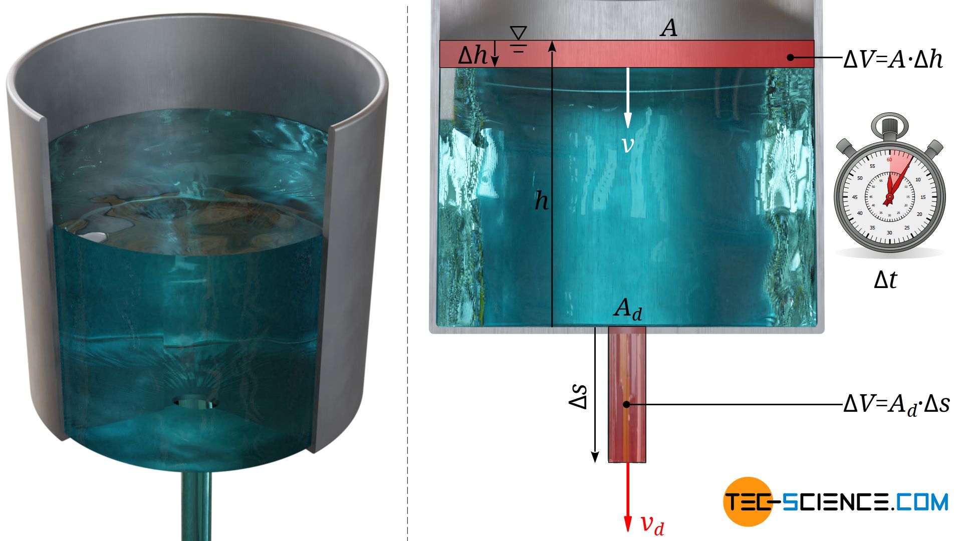
For this we consider a very small period of time ⋅Δt at an arbitrary head h. The liquid would drain through the opening at a constant velocity vd and thus cover the distance Δs=vd⋅Δt. The cross section of the hole Ad can now be used to determine the discharged liquid volume ΔV:
\begin{align}
\label{v1}
& \Delta V = \Delta s \cdot A_d = v_d \cdot \Delta t \cdot A_d \\[5px]
\end{align}
The discharging liquid causes the liquid level inside the tank to drop. Within the considered time period Δt), the velocity of descent is assumed to be constant and is denoted by v. Thus the liquid level drops within this time by the distance Δh=v⋅Δt. The liquid volume in the tank thus decreases by an amount ΔV analogous to the equation above:
\begin{align}
\label{v2}
& \Delta V = \Delta h \cdot A = v \cdot \Delta t \cdot A \\[5px]
\end{align}
Due to the already mentioned conservation of mass, the discharged volume according to equation (\ref{v1}) corresponds to the volume of liquid removed from the container according to equation (\ref{v2}). Both equations can thus be equated and a relation between the discharge velocity vd and the velocity of descent v is obtained:
\begin{align}
\require{cancel}
& v \cdot \bcancel{\Delta t} \cdot A = v_d \cdot \bcancel{\Delta t} \cdot A_d \\[5px]
\label{k}
& \boxed{v = \frac{A_d}{A} \cdot v_d} ~~~~~\text{continuity equation for incompressible substances} \\[5px]
\end{align}
Equation (\ref{k}) is also called continuity equation and ultimately describes mass conservation. In concrete terms, this means that the smaller the cross-section, the faster a liquid must flow, since the same mass must be moved through it within the same time. In this respect, the tank can be regarded as a pipe system whose cross-section tapers from A to Ad.
At this point, it becomes clear why the assumption of a constant container cross-section A over the height simplifies much in the following.This is because the velocity of descent and discharge velocity are always in the same ratio, independent of the filling level.
Torricelli’s law
Once the relationship between the velocity of descent and the discharge velocity has been clarified, the dependence of the discharge velocity on the head must be found. Torricelli’s theorem helps in the form of an equation (\ref{tl}), which can be used directly in equation (\ref{k}):
\begin{align}
\label{vv}
& \boxed {v = \frac{A_d}{A} \cdot \sqrt{2gh}} ~~~\text{velocity of descent} \\[5px]
\end{align}
At this point we can see in mathematical form what has already been explained. The velocity of descent depends on the liquid level, which in turn affects the level itself and thus influences the velocity of descent again. However, the velocity of descent is nothing more than the rate of change of the liquid level. I.e. the velocity of descent corresponds to the change of the level dh per time dt. The negative sign indicates that the level decreases with a positive velocity of descent.
\begin{align}
& \boxed {v = – \frac{\text{d}h}{\text{d}t}} \\[5px]
\end{align}
If one combines both equations, one finally obtains the following differential equation, which is to be solved:
\begin{align}
& -{\frac{\text{d}h}{\text{d}t} = \frac{A_d}{A} \cdot \sqrt{2gh}} \\[5px]
\end{align}
Solving the differential equation
In order to make the calculations clearer, the constant quantities in the differential equation are combined to the constant C):
\begin{align}
& \boxed{-\frac{\text{d}h}{\text{d}t} = C \cdot \sqrt{h}} ~~~\text{and } \boxed{C=\sqrt{2g} \cdot \frac{A_d}{A}}=\text{konstant} \\[5px]
\end{align}
To solve this differential equation, separate the variables h and t. I.e. all variables dependent on the variable h come on one side of the equation and all variables dependent on the variable t come on the other side of the equation. It does not matter which side the constant C is on, because it doesn’t depend on either of the two variables.
\begin{align}
& -\frac{\text{d}h}{ \sqrt{h}} = C \cdot \text{d}t \\[5px]
\end{align}
Both sides of the equation can now be integrated independently. The integration limits result from the following consideration. At time 0 the head is H and at any other time t the head is h.
\begin{align}
& -\int\limits_H^h \frac{\text{d}h}{ \sqrt{h}} = \int\limits_0^t C \cdot \text{d}t \\[5px]
& -\left[2\sqrt{h}\right]_H^h = C \cdot \left[ t \right]_0^t \\[5px]
& -2\left(\sqrt{h}-\sqrt{H}\right) = C \cdot t \\[5px]
& t = \frac{2}{C} \left(\sqrt{H}-\sqrt{h}\right)\\[5px]
\end{align}
For the sake of completeness, the constant C is applied in the equation above. The time t required to drain a container from the level H to the level h can be calculated using the following formula:
\begin{align}
& t = \frac{2}{ \underbrace{\sqrt{2g} \cdot \tfrac{A_d}{A}}_{=C} } \left(\sqrt{H}-\sqrt{h}\right)\\[5px]
\label{gl}
& \boxed{t = \frac{A}{A_d} \sqrt{\frac{2}{g}} \left(\sqrt{H}-\sqrt{h}\right)} \\[5px]
\end{align}
For a complete emptying of the tank h equals 0 and the discharge time t can be calculated using the following formula:
\begin{align}
&t_d = \frac{A}{A_d} \sqrt{\frac{2}{g}} \sqrt{H}\\[5px]
& \boxed{t_d = \frac{A}{A_d} \sqrt{\frac{2H}{g}}} ~~~\text{discharge time} \\[5px]
\end{align}
Remark
It was explained at the beginning that a high tank with the same filling volume drains faster than a wider one. The formula for calculating the discharge time seems to be contradictory. According to this equation, the discharge time increases when the liquid level is higher.
Of course, this is not a contradiction in terms, because with the same filling volume, the cross-sectional area of the container decreases to the same extent as the filling level increases. If, for example, the cross-sectional area is halved, the head doubles. However, for calculating the discharge time, the head ist taken into account by its square root. If the head is doubled, this would correspond to a factor of 1.4 (=√2). By halving the cross-sectional area, this reduces the discharge time by a factor of 0.7 (=√2⋅0.5).
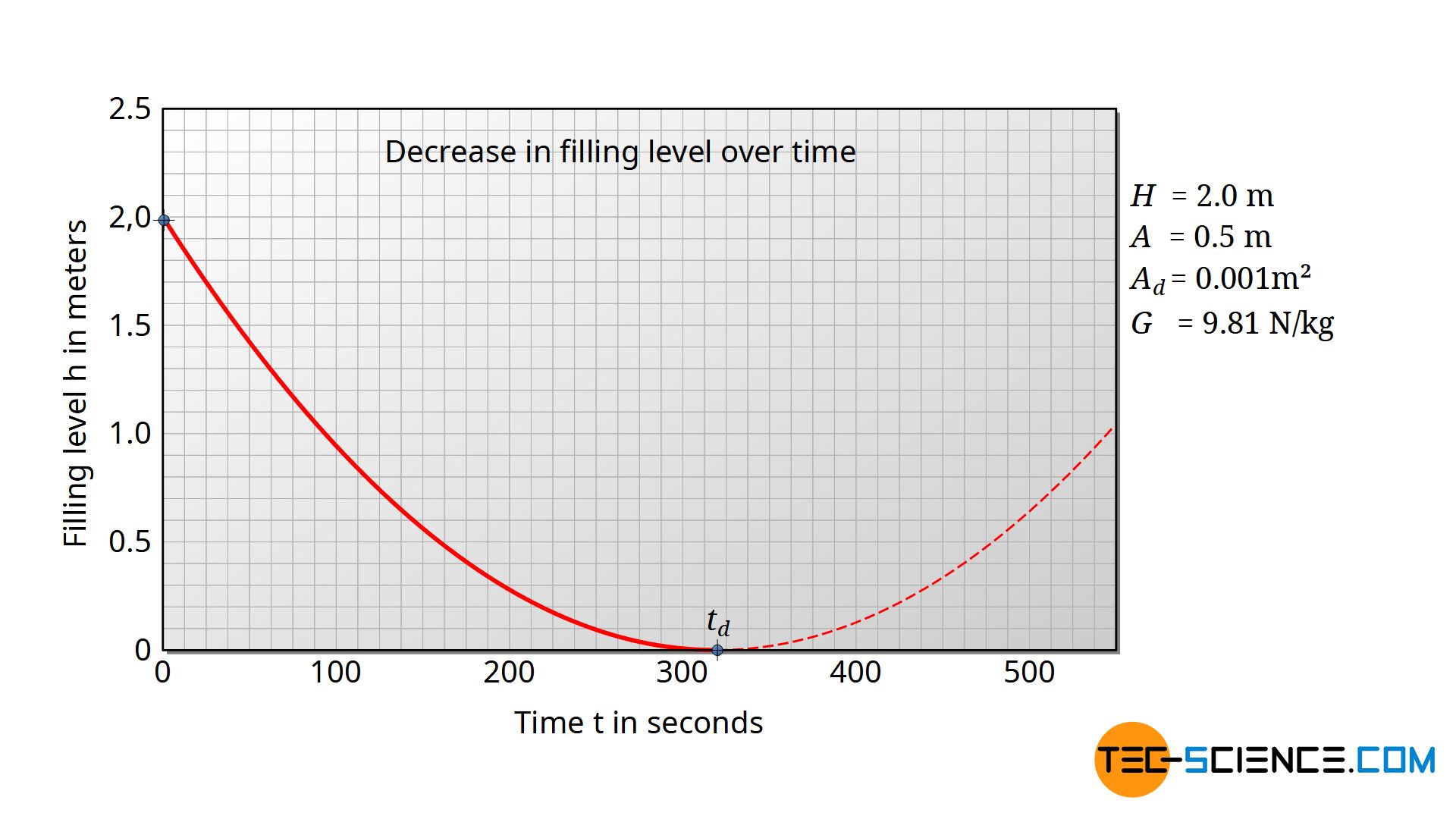
Decrease in liquid level over time
If one wants to calculate the decrease of the liquid level as a function of time, the equation (\ref{gl}) has to be rearranged for the liquid level h:
\begin{align}
t &= \frac{A}{A_d} \sqrt{\frac{2}{g}} \left(\sqrt{H}-\sqrt{h}\right) \\[5px]
\frac{A_d}{A} \sqrt{\frac{g}{2}} \cdot t &= \sqrt{H}-\sqrt{h} \\[5px]
\sqrt{h} &= \sqrt{H} – \frac{A_d}{A} \sqrt{\frac{g}{2}} \cdot t \\[5px]
h &= \left(\sqrt{H} – \frac{A_d}{A} \sqrt{\frac{g}{2}} \cdot t \right)^2 \\[5px]
\end{align}
\begin{align}
&\boxed{h(t) = \left(\sqrt{H} – \frac{A_d}{A} \sqrt{\frac{g}{2}} \cdot t \right)^2} \\[5px]
\end{align}
The level thus decreases quadratically over time. The apex of the parabola corresponds to the time at which the container is completely discharged.
Volumetric flow rate of discharge (rate of efflux)
According to the equation (\ref{vv}) the discharge velocity v can be calculated for each head h. Therefore, it is also possible to calculate the volumetric flow rate of discharge V* (also referred to as rate of efflux or just discharge rate) of the fluid flowing through the outlet. The volumetric flow rate is the volume of liquid ΔV per time Δt that exits the tank:
\begin{align}
&\boxed{\dot V = \frac{\Delta V}{\Delta t}} ~~~\left[\dot V \right] = \frac{\text{m³}}{\text{s}}~~~\text{volumetric flow rate of discharge} \\[5px]
\end{align}
The discharge rate V* can be determined according to this definition by rearranging the equation (\ref{v1}):
\begin{align}
& \Delta V = A_d \cdot v_d \cdot \Delta t \\[5px]
\label{vd}
& \frac{ \Delta V }{\Delta t} = \boxed{\dot V = A_d \cdot v_d} \\[5px]
\end{align}
Finally, the discharge velocity due to the equation (\ref{tl}) can now be used in equation (\ref{vd}) to calculate the discharge rate as a function of head:
\begin{align}
\label{dV}
& \boxed{\dot V = A_d \cdot \sqrt{2gh} } \\[5px]
\end{align}
Influence of velocity of descent on discharge velocity
It has already been said that the derived formulas only apply as long as the velocity of descent is negligibly small compared to the discharge velocity. Especially with large openings, however, a lot of liquid can flow out. The level then drops relatively quickly. According to Torricelli’s theorem, this is no longer a simple free fall, but a free fall with an initial velocity. The initial velocity corresponds to the velocity of descent of the liquid level at the current time.
From an energetic point of view, a considered amount of liquid on the surface has therefore not only positional energy (m⋅g⋅h) but also kinetic energy (½⋅m⋅v2). In this general case the following formula results for the discharge velocity vd:
\begin{align}
\require{cancel}
& \bcancel{m} \cdot g \cdot h + \frac{1}{2} \cdot \bcancel{m} \cdot v^2 = \frac{1}{2} \cdot \bcancel{m} \cdot v_d^2 \\[5px]
\end{align}
\begin{align}
&\boxed{v_d=\sqrt{v^2+2gh}} \\[5px]
\end{align}
The discharge velocity is higher when the liquid surface sinks rapidly. The outflowing liquid draws additional kinetic energy from the drop in the liquid level so to speak. Of course, the continuity equation according to equation (\ref{k}) still applies. Thus, the velocity of descent v and discharge velocity vd are now related as in the following way:
\begin{align}
& v = \frac{A_d}{A} \cdot v_d \\[5px]
& v = \frac{A_d}{A} \cdot \sqrt{v^2+2gh} \\[5px]
\end{align}
Solving this equation for the velocity of descent v:
\begin{align}
& \boxed{v = \color{red}{\tfrac{1}{\sqrt{ 1- \left(\tfrac{A_d}{A}\right)^2 }}} \cdot \frac{A_d}{A} \cdot \sqrt{2gh} } \\[5px]
\end{align}
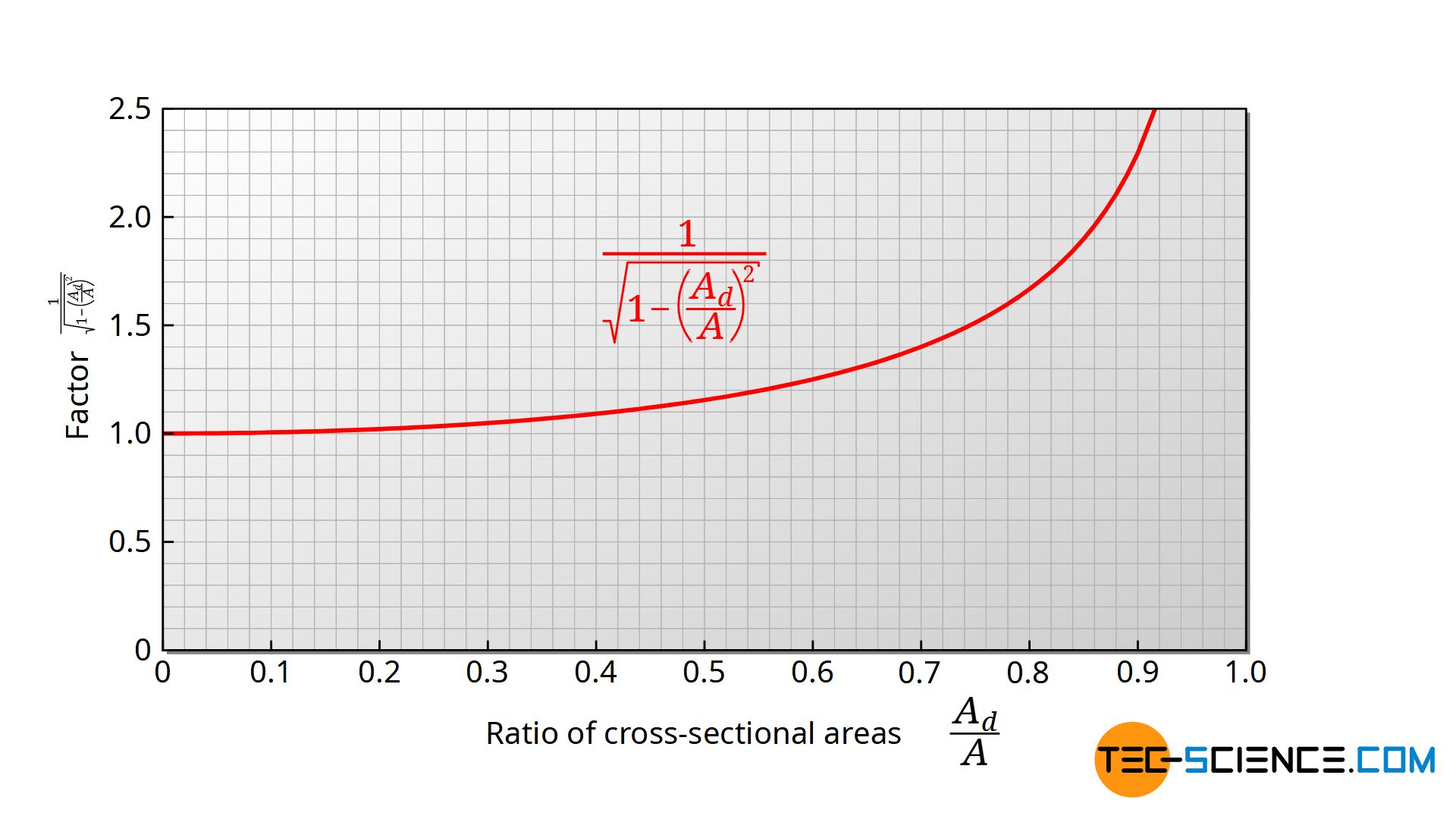
If one compares this formula with the formula (\ref{vv}) (which was obtained by neglecting the velocity of descent), the two formulas differ only by the term marked in red. This geometric term is ultimately only determined by the ratio of the cross-sectional areas of the opening and the tank. The figure below shows the course of this term as a function of the ratio. If the cross-section of the opening is smaller than 10 % of the container cross-section, then this factor is only 1.005. The influence of the velocity of descent remains negligible below a cross-section ratio of 0.1! This should apply to many cases.
In cases where this does not apply, this factor must be taken into account. Accordingly, this has an effect on the discharge velocity vd, the discharge time t and the discharge flow rate V* (the additional term is marked in red compared to the neglect of the sink rate):
\begin{align}
& \boxed{v_d = \color{red}{\tfrac{1}{\sqrt{1-\left(\tfrac{A_d}{A}\right)^2}}} \cdot \sqrt{2gh} } \\[5px]
\end{align}
\begin{align}
& \boxed{\dot V = \color{red}{\tfrac{1}{\sqrt{1-\left(\tfrac{A_d}{A}\right)^2}}} \cdot A_d \cdot \sqrt{2gh} } \\[5px]
\end{align}
\begin{align}
& \boxed{t = \color{red}{\sqrt{1-\left(\tfrac{A_d}{A}\right)^2}} \cdot \frac{A}{A_d} \sqrt{\frac{2}{g}} \left(\sqrt{H}-\sqrt{h}\right)} \\[5px]
\end{align}
Discharge through large openings
So far it was assumed that the dimension of the opening was small compared to the head. This assumption is particularly advantageous for sideways discharges. This gives a (nearly) constant pressure over the entire opening and therefore a nearly constant discharge velocity. If, on the other hand, the opening is relatively high, the hydrostatic pressure at the upper edge is lower than at the lower edge. Consequently, the discharge velocities also differ across the opening.
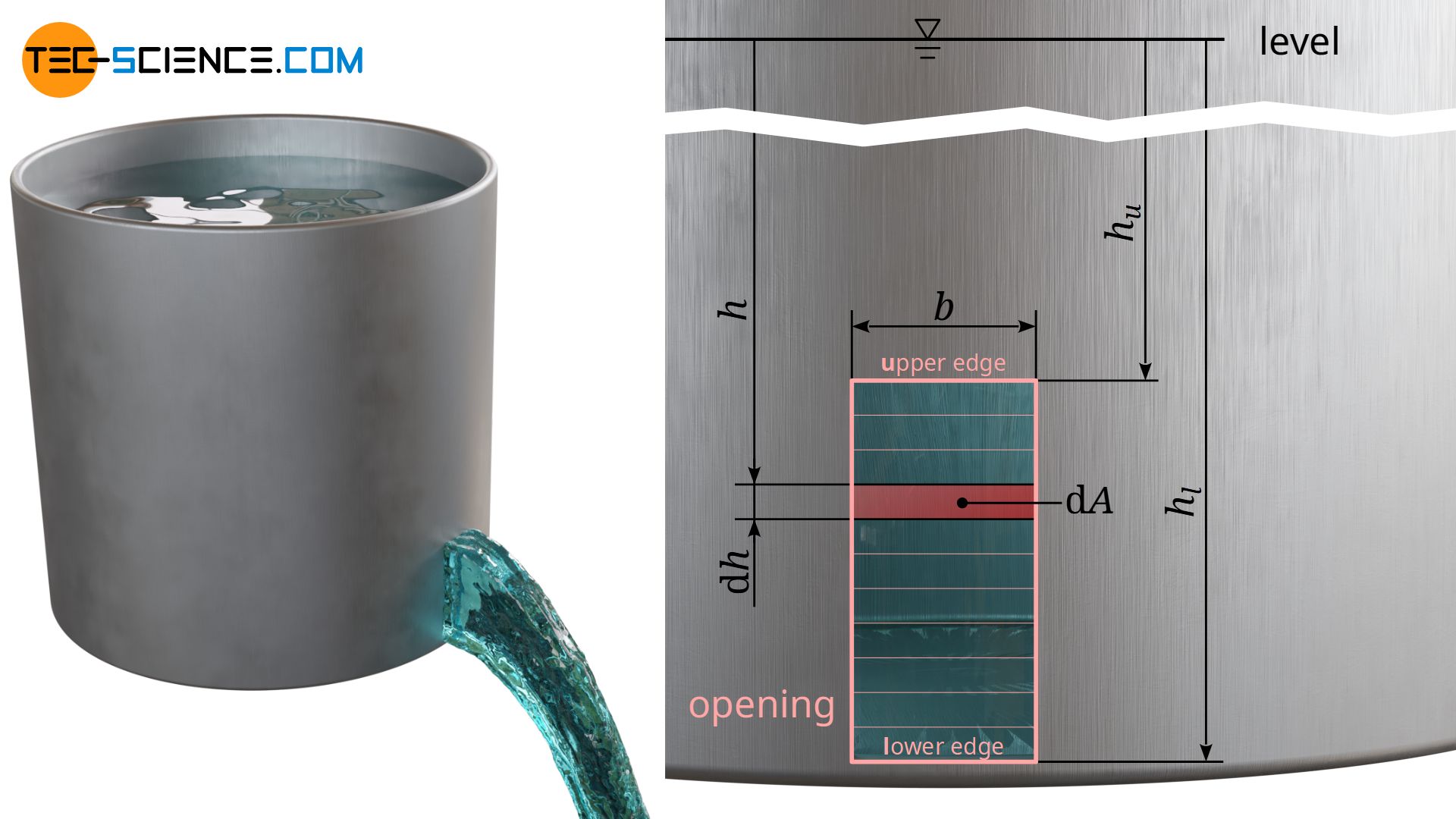
For the sake of simplicity, a rectangular discharge cross-section is considered on the side of a tank (see figure above). Imagine the opening as being made up of many small “slots”. The cross-sectional area dAd of such a slot results from the product of slot width b and slot height dh. Through each slot at the depth h the respective volumetric flow rate dV* can be calculated according to the equation (\ref{dV}):
\begin{align}
& \text{d} \dot V = \text{d}A_d \cdot \sqrt{2gh} = b \cdot \text{d} h \cdot \sqrt{2gh} \\[5px]
& \text{d} \dot V = b \cdot \sqrt{2gh} \cdot \text{d}h \\[5px]
\end{align}
According to the defined coordinate system, this equation is to be integrated within the limits of hu (upper edge of opening) and hl (lower edge of opening) and thus provides the total discharge rate V* through the entire opening:
\begin{align}
\dot V &= \int\limits_{h_u}^{h_l} b \cdot \sqrt{2gh} \cdot \text{d}h \\[5px]
&= \sqrt{2g} \cdot b \int\limits_{h_u}^{h_l} \sqrt{h} \cdot \text{d}h \\[5px]
&=\sqrt{2g} \cdot b \int\limits_{h_u}^{h_l} h^{\frac{1}{2}} \cdot \text{d}h \\[5px]
&=\tfrac{2}{3} \sqrt{2g} \cdot b \cdot |h^{\frac{3}{2}}| _{h_u}^{h_l} \\[5px]
&= \tfrac{2}{3} \sqrt{2g} \cdot b \cdot \left(h_u^{\frac{3}{2}} – h_l^{\frac{3}{2}} \right) \\[5px]
\end{align}
\begin{align}
&\boxed{\dot V = \tfrac{2}{3} \sqrt{2g} \cdot b \cdot \left(\sqrt{h_l^3} – \sqrt{h_u^3} \right)} \\[5px]
\end{align}
Note that the indicated depths hu and hl do not refer to the tank bottom, but to the liquid surface!
Real discharge processes
Coefficient of discharge
If one compares the theoretical predictions about the discharge process of a tank with a real measurement, very large differences can be found in some cases. In reality, the tank usually drains much more slowly.
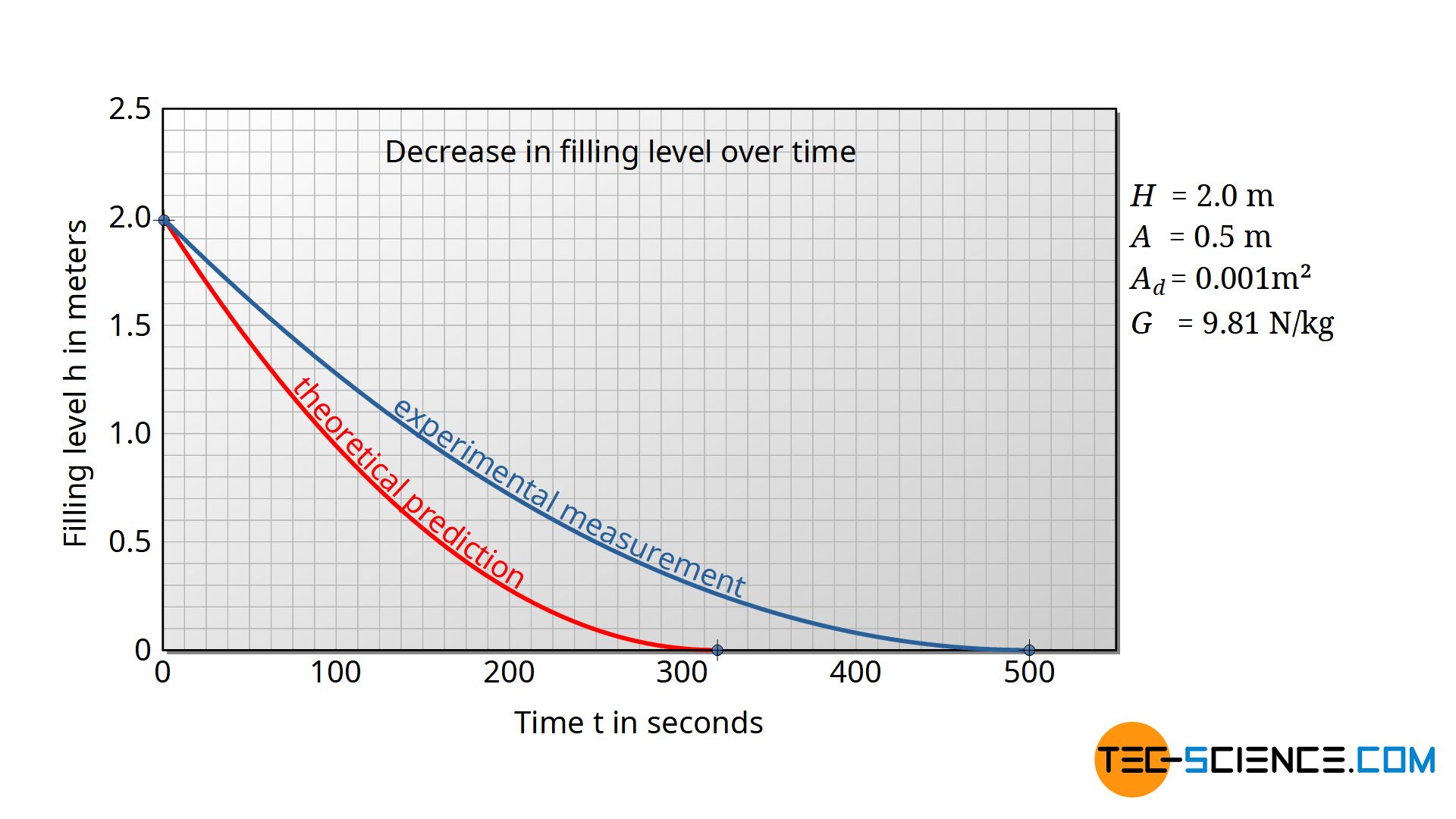
The outgoing flow rate according to the equation (\ref{dV}) is therefore lower in practice. The reduction of the ideal discharge rate can be considered with a so-called coefficient of discharge Cd<1:
\begin{align}
& \dot V_{\text{real}} = C_d \cdot V_{\text{ideal}} \\[5px]
\label{t}
& \boxed{\dot V_\text{real} = C_d \cdot A_d \sqrt{2gh} ~} ~~~\text{and } C_d <1 ~~~\text{coefficient of discharge}\\[5px]
\end{align}
The coefficient of discharge indicates the factor by which the real discharge rate is reduced in comparison to the ideal rate! Two phenomena have a significant influence on the coefficient of discharge and will be discussed in more detail below.
Viscosity (internal friction)
When draining through an orifice, currents occur within the liquid. This means that layers of liquid move faster than others. This is particularly the case in the vicinity of the discharge, where the liquid flowing towards the orifice shears off at the surrounding layers. The friction of the liquid layers is due to the bonding forces between the molecules within the layers. These are either Van-der-Waals forces (dipole-dipole interactions) or hydrogen bonds.
In order to shift one layer of liquid against another, one must overcome these binding forces. Liquid layers are therefore hindered from shearing off from each other by these binding forces, analogous to friction forces in mechanics. This is why in the case of liquids one also speaks of internal friction. The stronger the bonding forces, the greater the internal friction when the liquid layers are shifted. The magnitude of the internal friction is described by the viscosity of the liquid.
Coefficient of velocity
Viscosity is the reason why in reality a liquid flows through an outlet at a slower speed than theoretically expected. The decrease of the discharge velocity can be considered with a so-called coefficient of velocity Cv<1 in equation (\ref{tl}):
\begin{align}
&v_\text{d,real} = C_v \cdot v_\text{d,ideal} \\[5px]
\label{vvv}
& \boxed {v_\text{d,real} = C_v \cdot \sqrt{2gh}} ~~\text{and } C_v<1 ~\text{coefficient of velocity} \\[5px]
\end{align}
Experimental determination of the coefficient of velocity
For horizontal discharges, the coefficient of velocity can be determined from the trajectory of the jet. Neglecting the air friction, the jet maintains a constant (discharge) velocity vd,real in the horizontal direction. Thus the jet covers the following distance x within a time t:
\begin{align}
&x = v_{\text{d,real}} \cdot t \\[5px]
\end{align}
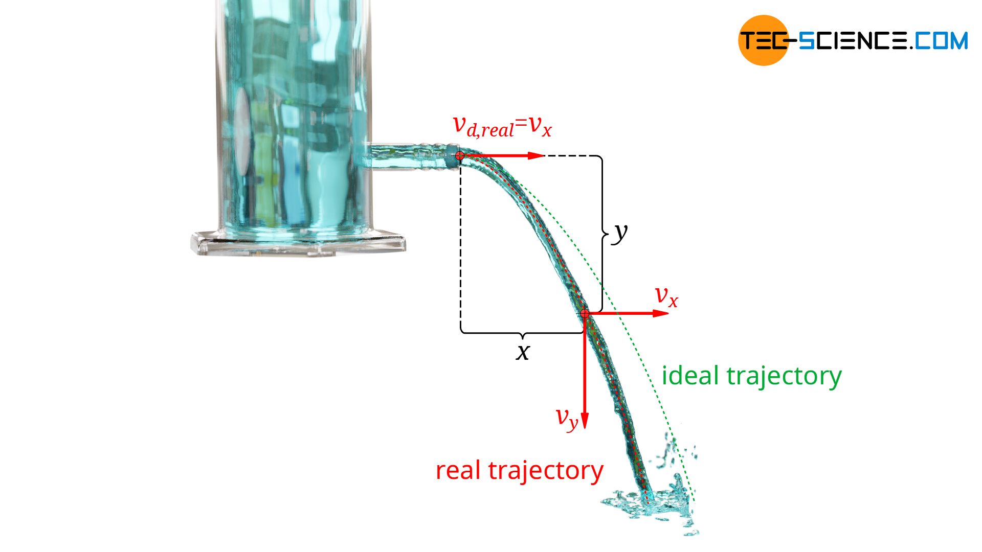
Within the time t gravity causes an accelerated downward motion of the jet (free fall). For the falling distance y in vertical direction, the formula given below applies. This equation is then solved for the time t and used in the equation above and solved with respect to the discharge velocity vd,real.
\begin{align}
&y = \frac{1}{2} \cdot g \cdot t^2 ~~~~\Rightarrow ~~~~t = \sqrt{\frac{2y}{g}} \\[5px]
& x = v_{\text{d,real}} \cdot t = v_{\text{d,real}} \cdot \sqrt{\frac{2y}{g}} \\[5px]
& \underline{v_{\text{d,real}} = x \cdot \sqrt{\frac{g}{2y}}} \\[5px]
\end{align}
This equation is now to be equated with equation (\ref{vvv}) and solved with respect to the coefficient of velocity Cv:
\begin{align}
& C_v \cdot \sqrt{2gh} = x \cdot \sqrt{\frac{g}{2y}} \\[5px]
& \boxed{ C_v = \frac{x}{2 \sqrt{hy}}} \\[5px]
\end{align}
For the experimental determination of the coefficients of velocity only one point of the trajectory (described by x and y) has to be determined. Tests on such trajectories show that for low-viscosity liquids such as water, the coefficients of velocity are about 0.95 and higher.
The small decreases in discharge velocity cannot therefore be solely responsible for the relatively large deviations between the theoretical discharge rate and the observed rate. A much greater phenomenon must have an influence on this, which we will discuss in more detail in the next section.
Contraction of streamlines
Streamlines
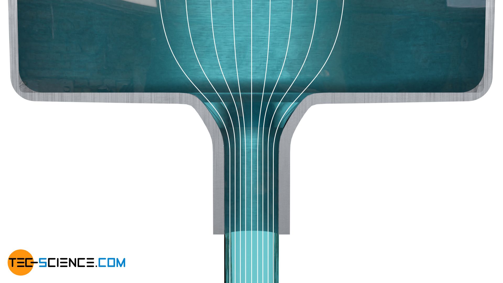
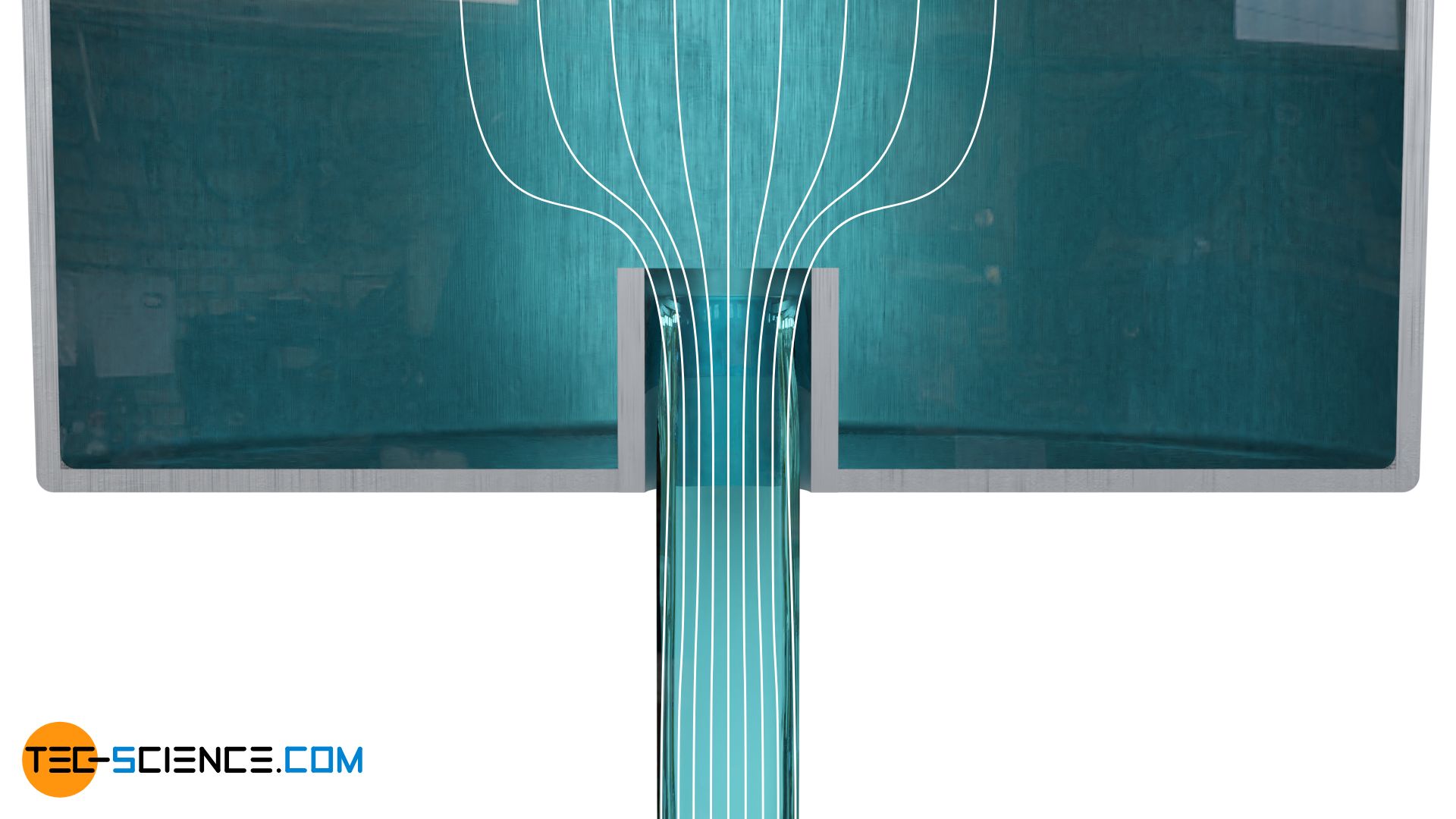
Practice shows that the position and the shape of the discharge are decisive for the deviations in the volumetric flow rate. The influence is particularly evident at sharp-edged transitions between the tank and the outlet opening. A simple hole in a tank is such a sharp edge. The figure below shows a tank in which the discharge takes place through a round hole at the bottom. The flow paths are made visible by so-called streamlines (white lines in the figure below). Such streamlines are paths on which massless particles would flow if they were placed in the fluid.
Streamlines are trajectories that massless particles would take when flowing with the fluid!
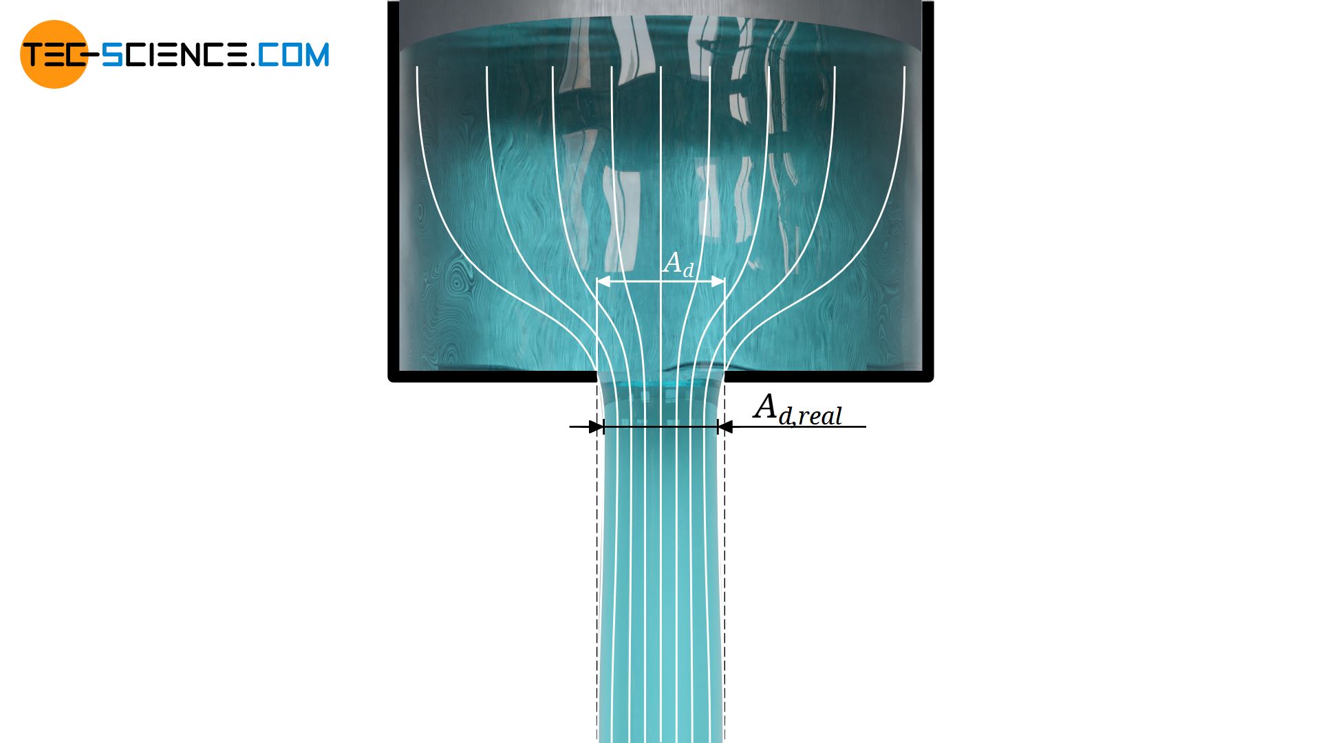
The streamlines made visible also provide the answer to the question of why a lower discharge rate is observed in practice than the model so far predicts. In practice, the outflowing liquid does not exits completely perpendicular through the cross-section, but the opening is mostly flowed against from the side. From a physical point of view, the flow paths (streamlines) cannot bend at right angles. To do this, the fluid would have to be massless in order to be able to follow the forces without inertia.
Coefficient of contraction
In practice, the cross-section of the discharged jet is thus smaller than the cross-section of the outlet. This cross-section, in which the streamlines actually run parallel downwards, is located downstream of the opening. This is the actual cross-section of discharge Ad,real which one would have to take as a basis. This cross-section is also called the effective cross-section. The phenomenon of the narrowing of streamlines and the resulting decrease of the jet cross-section is also known as vena contracta.
The term vena contracta refers to the contraction of the streamlines due to cross-sectional changes, i.e. the narrowing of the jet cross-section less than the actual tube cross-section.
The decrease of the jet cross-section is considered by the so-called coefficient of contraction Cc. It indicates the ratio of the actual jet cross-section Ad,real to the discharge cross-section Ad:
\begin{align}
& \boxed {A_\text{d,real} = C_c \cdot A_\text{d} } ~~~\text{and } C_c<1 ~~~\text{coefficient of contraction} \\[5px]
\end{align}
Relationship between discharge coefficient, velocity coefficient and contraction coefficient
Both the phenomenon of speed reduction and the far greater effect of streamline contraction influence the volumetric flow rate in practice. If the flow rate is based on the real values according to the equation (\ref{vd}), then the following relationship is evident between the coefficient of discharge Cd, the coefficient of contraction Cc and the coefficient of velocity Cv:
\begin{align}
\dot V_\text{d,real} &= A_\text{d,real} \cdot v_\text{d,real} \\[5px]
&= \underbrace{ C_c \dot A_d}_{ A_\text{d,real} } \cdot \underbrace{C_v v_d}_{ v_\text{d,real} } \\[5px]
&= C_c \cdot C_v \cdot A_d v_d ~~~\text{and }~~~ v_d=\sqrt{2gh} ~~~\text{:}\\[5px]
\label{u}
& = \underbrace{ C_c \cdot C_v }_{= C_d } \cdot A_d \sqrt{2gh} \\[5px]
\end{align}
\begin{align}
& \boxed{\dot V_\text{d,real} = C_d \cdot A_d \sqrt{2gh}} ~~~\text{und}~~~ \boxed{ C_d = C_c \cdot C_v } \\[5px]
\end{align}
If one compares equation (\ref{u}) with equation (\ref{t}), then it becomes apparent that the discharge coefficient Cd results from the product of the contraction coefficient Cc and the velocity coefficient Cv. Since the coefficient of velocity for fluids commonly used in practice is usually negligible compared to the coefficient of contraction, the coefficient of discharge is decisively determined by the vena contracta. In practice, however, one is usually only interested in the discharge coefficient anyway, so that the velocity coefficient and the contraction coefficient are not determined separately.
Experimental determination of the coefficient of discharge
The coefficient of discharge directly influences the time required to empty a container. The discharge coefficient has therefore a direct impact on the equation (\ref{gl}) and increases the discharge time accordingly:
\begin{align}
& \boxed{t = \frac{1}{ C_d } \cdot \frac{A}{A_d} \sqrt{\frac{2}{g}} \left(\sqrt{H}-\sqrt{h}\right)} \\[5px]
\end{align}
In practice, one only has to determine the time t during which the liquid level decreased from the level H to the level h. Solving the above equation with respect to the discharge coefficient:
\begin{align}
& \boxed{ C_d = \frac{1}{t} \cdot \frac{A}{A_d} \sqrt{\frac{2}{g}} \left(\sqrt{H}-\sqrt{h}\right)} \\[5px]
\end{align}
Influence of the shape of the outlet on the coefficient of discharge
Round openings
In the case of a round hole in a tank, the coefficient of discharge for water is about 0.65. In practice, a high discharge coefficient is usually desirable in order to get as close as possible to the ideal (maximum) volumetric flow rate. This requires a adaptation of the opening shape.
Since the discharge coefficient is decisively determined by the vena contracta, the contraction of the streamlines must be kept as low as possible. This is achieved by adjusting the geometry of the opening. A simple possibility is to use pipe sockets. The liquid then does not flow out of the tank straight away, but is led through a short piece of pipe.This ensures that the streamlines can be arranged parallel again and can occupy the entire cross-section.
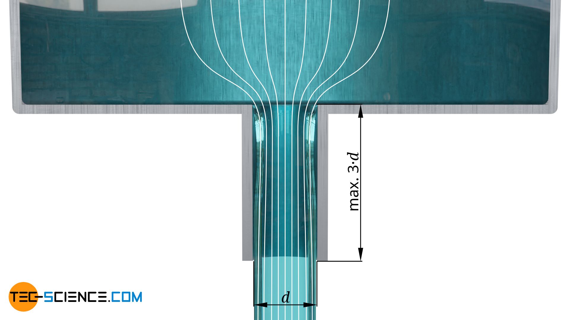
In order to achieve an optimal effect, pipe sockets should be about 2 to a maximum of 3 times as long as their diameter. Within this range, it is possible to increase the discharge rate by about 25 % compared to the discharge at sharp-edged openings leading directly into the environment. For reasons of increased pipe friction, the pipe sockets should be kept as short as possible.
A further increase in the discharge rate can be achieved by rounding out the edges (“fairing”) so that the streamlines are smoothly guided around these edges. In this way, discharge coefficients above 0.9 and higher are possible.
In contrast, the discharge can also be made considerably less favourable than with a hole. For example, if a short pipe socket does not protrude from the tank, but into it. Then the streamlines make very strong changes with a more pronounced vena contracta. Such an unfavourable arrangement of a pipe socket is also called Borda’s opening. The coefficients of dicharge are about 0.53.
Rectangular openings
Until now, round openings were tacitly assumed. Above all, however, when liquids discharge sideways, the shape of the cross-section has a very strong influence on the coefficient of discharge. With rectangular openings, it is always unfavorable if liquid flows into the opening from the side. In this way the streamlines show very strong changes in direction. Therefore, the opening height should be kept as low as possible and the width should be greater than the height.
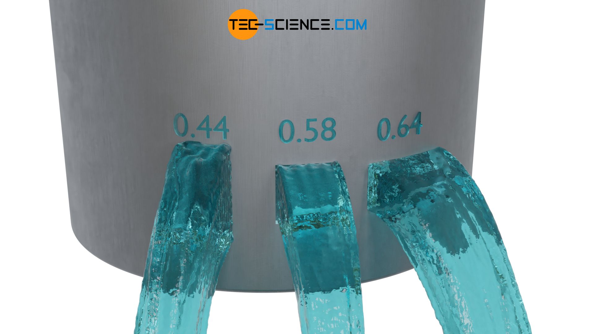
For square openings where the opening height corresponds to the opening width, the discharge coefficient is about 0.58. If the opening height is twice as large as the opening width, the discharge coefficient drops to about 0.44. If the opening height is only half the opening width, the discharge coefficient rises to 0.64. Although the opening height can be further reduced, a maximum discharge coefficient of 0.67 can be achieved with rectangular openings.
")


")
")
