In this article, learn more about the maximum belt stress, which must not be exceeded, otherwise the belt will be damaged.
Introduction
In general, the forces acting in the belt must not exceed certain limits, as otherwise the belt will be damaged and will either deform unacceptably or even tear. Therefore, certain stress limits apply, which may not be exceeded depending on the belt material. Whether these requirements are met depends on the forces acting on the cross-section of the belt during operation.
Besides the quasi-static belt span forces (relevant for power transmission), the centrifugal belt forces also act during operation. The resulting stresses σ are obtained by referring the forces to the cross-sectional area A of the belt:
\begin{align}
\sigma_t &= \frac{F_t}{A} &&~~~\text{tight side tension} \\[5px]
\sigma_s &= \frac{F_s}{A} &&~~~\text{slack side tension} \\[5px]
\sigma_{cf} &= \frac{F_{cf}}{A} &&~~~\text{centrifugal tension} \\[5px]
\end{align}
Centrifugal tension
For the centrifugal tension in the belt, the formula derived from the article Centrifugal forces applies, where m’ corresponds to the specific mass of the belt (“mass per unit length”):
\begin{align}
F_{cf}= m’ \cdot v^2 ~~~~~\text{and} ~~~~~ m’ = \frac{m}{L},
\end{align}
The centrifugal tension (or rather centrifugal stress) acting in the belt therefore applies:
\begin{align}
&\sigma_{cf} = \frac{F_{cf}}{A} = \frac{m’ \cdot v^2}{A} = \frac{m\cdot v^2}{\underbrace{L \cdot A}_{\text{volume } V}} = \frac{m\cdot v^2}{V} = \underbrace{\frac{m}{V}}_{\text{density } \rho} \cdot v^2 = \rho \cdot v^2 \\[5px]
&\boxed{\sigma_{cf} = \rho \cdot v^2} \\[5px]
\end{align}
Note, that the term L⋅A is the belt volume V and the term m/V corresponds to the density ϱ of the belt material. Thus, the centrifugal tension in the belt depends only on the belt density and the belt speed.
Bending stress
In addition to the above mentioned stresses, bending stresses σb must also be taken into account when rotating the belt around the pulleys. The belt is stretched in the outer areas and compressed in the inner areas; the neutral axis runs in-between and is neither stretched (necked) nor compressed (bulged).
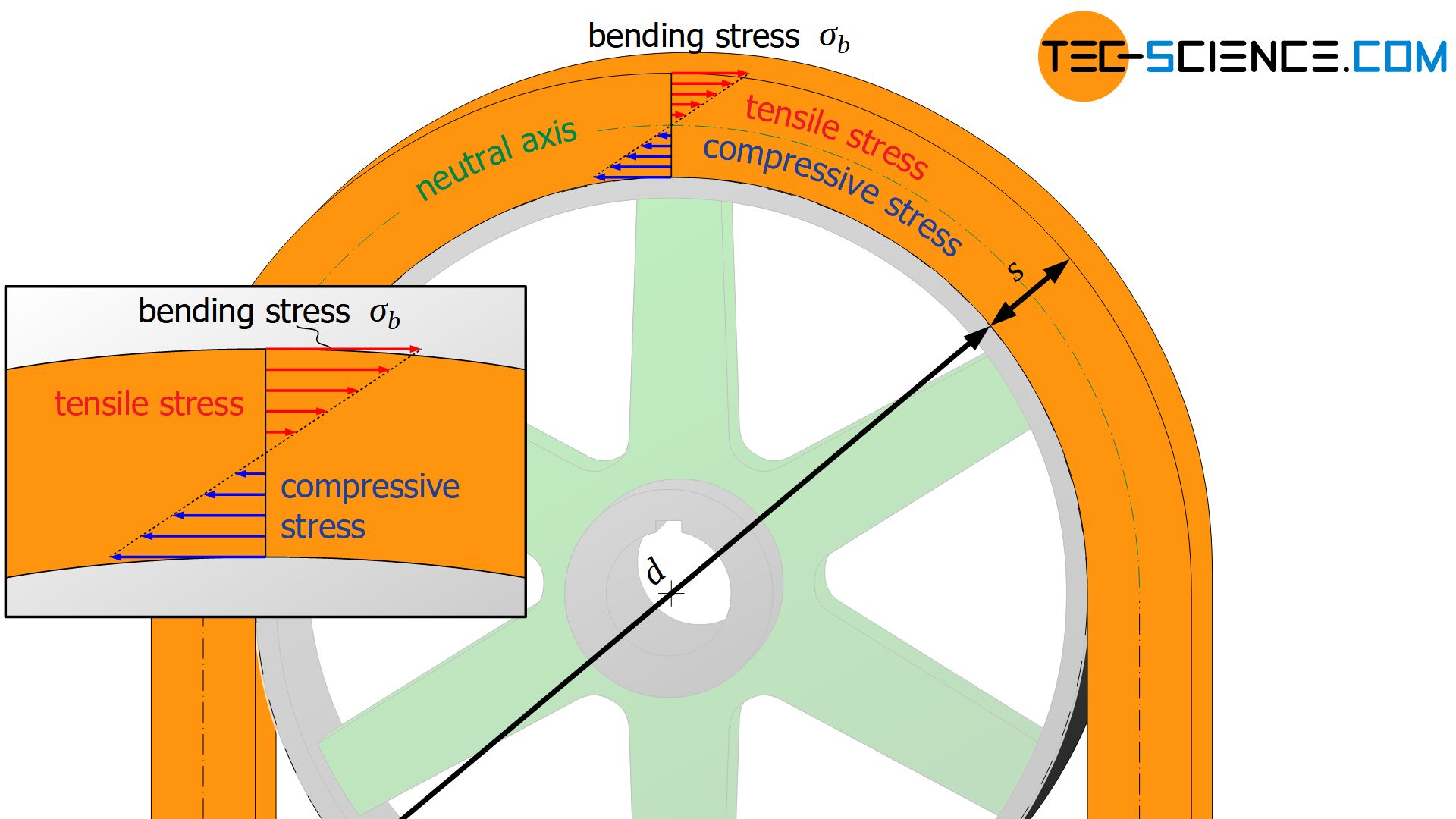
The strains lead to tensile stresses in the outer and to compressive stresses in the inner belt area. In the case of a belt drive, only tensile stresses are decisive, as these also have a pulling effect in addition to the span forces and the centrifugal forces and the belt is thus subjected to maximum stress in these outer areas.
Starting from the neutral axis, the tensile stresses caused by bending increase as the elongation increases. The tensile stress reaches its maximum at the outer edge of the belt. This maximum stress is referred to as bending stress σb.
It can be assumed that the stronger the belt is bent (i.e. the smaller the pulley) and the thicker the belt, the greater the bending stresses. According to the linear-elastic bending theory, the bending stress σb at a given bending radius or bending diameter d (=diameter of the pulley) and at a given thickness s of the belt, can be determined using the so-called bending modulus Eb) (flexural modulus) of the belt material (the bending modulus should not be confused with the Young’s modulus from the tensile test!):
\begin{align}
\boxed{\sigma_b = E_b \cdot \frac{s}{d + s}} ~~~\text{bending stress} \\[5px]
\end{align}
Note that the drawings above are not to scale. Especially with flat belts, the belt thickness is considerably smaller than the belt width. This also applies to the ratio of pulley diameter to belt thickness, which is in the order of about 50 to 100, i.e. the pulley diameter is 50 to 100 times larger than the belt thickness.
For this reason, the belt thickness s compared to the diameter d of the pulley can often be neglected. In these cases, the bending stresses can then also be determined using the formula given below, whereby the actual bending stresses are lower than those calculated as a result of the conservative simplification.
\begin{align}
\sigma_b = E_b \cdot \frac{s}{d + \underbrace{s}_{\ll d}} \approx E_b \cdot \frac{s}{d} \\[5px]
\end{align}
It can now be seen that the bending stresses are directly dependent on the ratio of belt thickness to pulley diameter. The smaller the pulley radius and the thicker the belt, the greater the bending stresses. This means that the greatest bending stress occurs when the belt rotates around the smaller of the two pulleys (usually the drive pulley)!
The largest belt tensions occur when the belt rotates around the smaller of the two pulleys!
Distribution of the belt tension
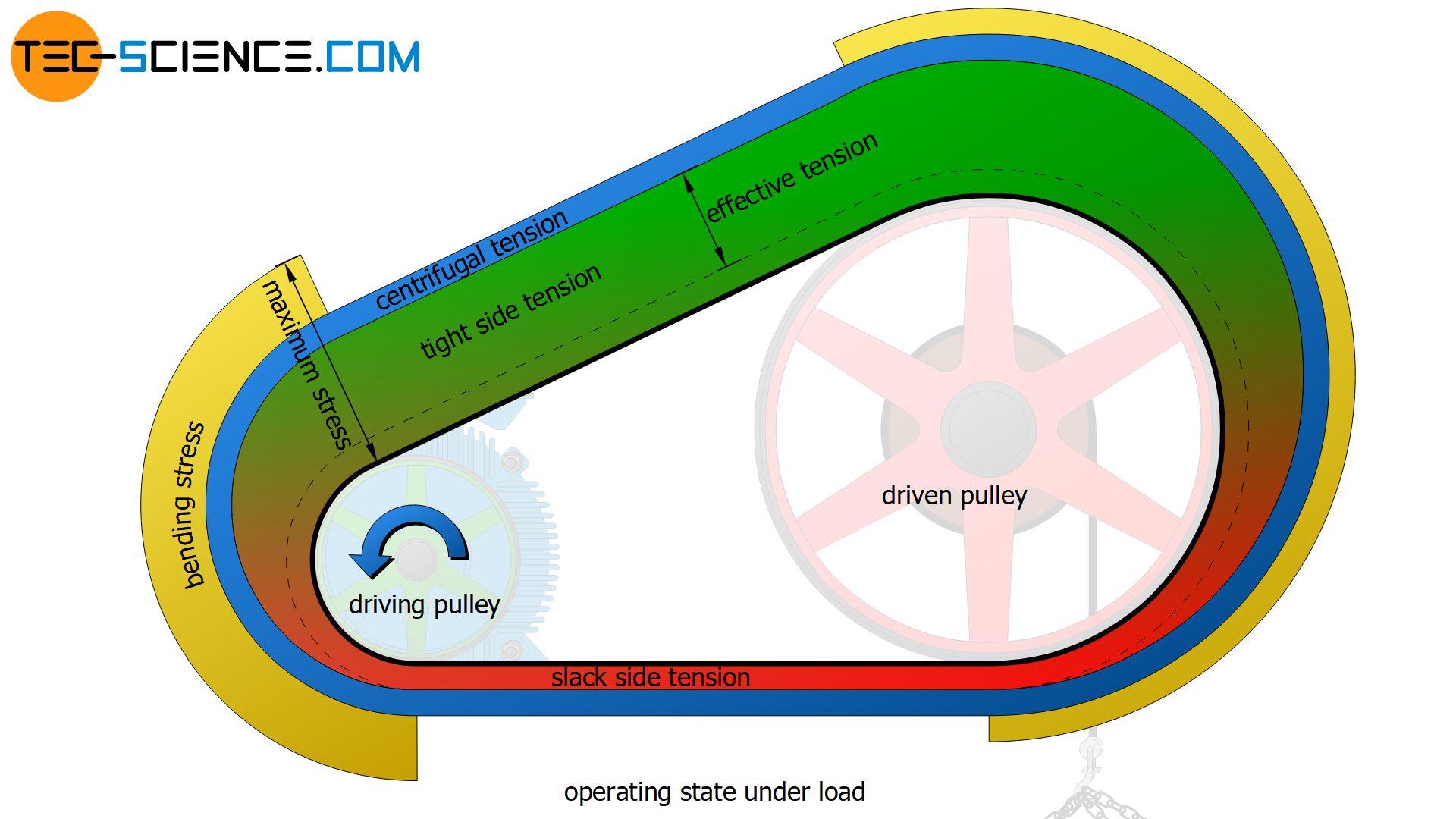
The figure below schematically shows the distribution of the belt tension. The effective tension used for power transmission is denoted by σc (circumferential force Fc related to the belt cross section A). This effective tension results from the difference between the tight side tension σt and the slack side tension σs (see also article Power transmission of a belt drive):
\begin{align}
\sigma_c = \frac{F_c}{A} = \frac{F_t – F_s}{A} = \frac{F_t}{A} – \frac{F_s}{A} = \sigma_t – \sigma_s \\[5px]
\end{align}
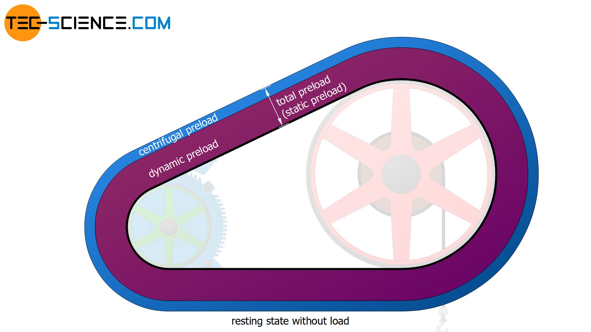
In comparison to the figure above, the figure below shows the distribution of the belt tension in the load-free idle state. The total preload is divided into a part that ensures the force-transmitting contact pressure in later operation (dynamic preload) and a part to compensate for centrifugal forces (centrifugal preload).
Maximum belt tension
While the centrifugal tension σcf acts equally throughout the belt during operation and the quasi-static tensions σt and σs are only present to this extent in the corresponding belt sections, the bending stress acts only during rotation around pulleys, with the largest bending stress acting on the smaller drive pulley (see figure above).
The maximum belt stress therefore occurs on the slack side, where the belt runs onto the smaller of the two pulleys (provided that the smaller of the two pulleys is the drive pulley, otherwise the greatest bending stress would be present when the belt runs off).
The maximum belt stress σmax results from the sum of the tight side stress σt, the centrifugal stress σcf and the bending stress σb. The dimensioning of the belt depends on this maximum stress. Always ensure that the maximum permissible belt stress σper is not exceeded.
\begin{align}
\label{zulaessige}
\boxed{\sigma_{max} = \sigma_t + \sigma_{cf}+ \sigma_b} \le \sigma_{per}\\[5px]
\end{align}
Bending frequency
Bending processes in the belt always take place during each revolution around a pulley. Regardless of whether it is a drive or output pulley or tensioner pulleys, guide pulleys, idler pulleys, etc. With every bending process the belt is deformed, which is connected with an strain energy to be applied. The smaller the pulley, the greater the strain energy and the more the belt heats up.
The strain energy to be applied not only reduces the efficiency but also puts a great stress on the belt both mechanically and thermally. The more bending processes a belt goes through per time, i.e. the higher the bending frequency fb, the shorter its service life will be.
Therefore, depending on the type and manufacturer, the belt must not exceed a certain permissible bending frequency fb,per. The bending frequency fb itself is determined by the belt length L, the belt speed v and the number of pulleys z:
\begin{align}
\boxed{f_b = \frac{z \cdot v }{L} }\le f_{b,per} ~~~~~[f] = \frac{1}{\text{s}} = \text{Hz}\\[5px]
\end{align}


