The points of contact of two meshing tooth flanks describe a straight line for involute gears (line of action or line of engagement).
Line of action
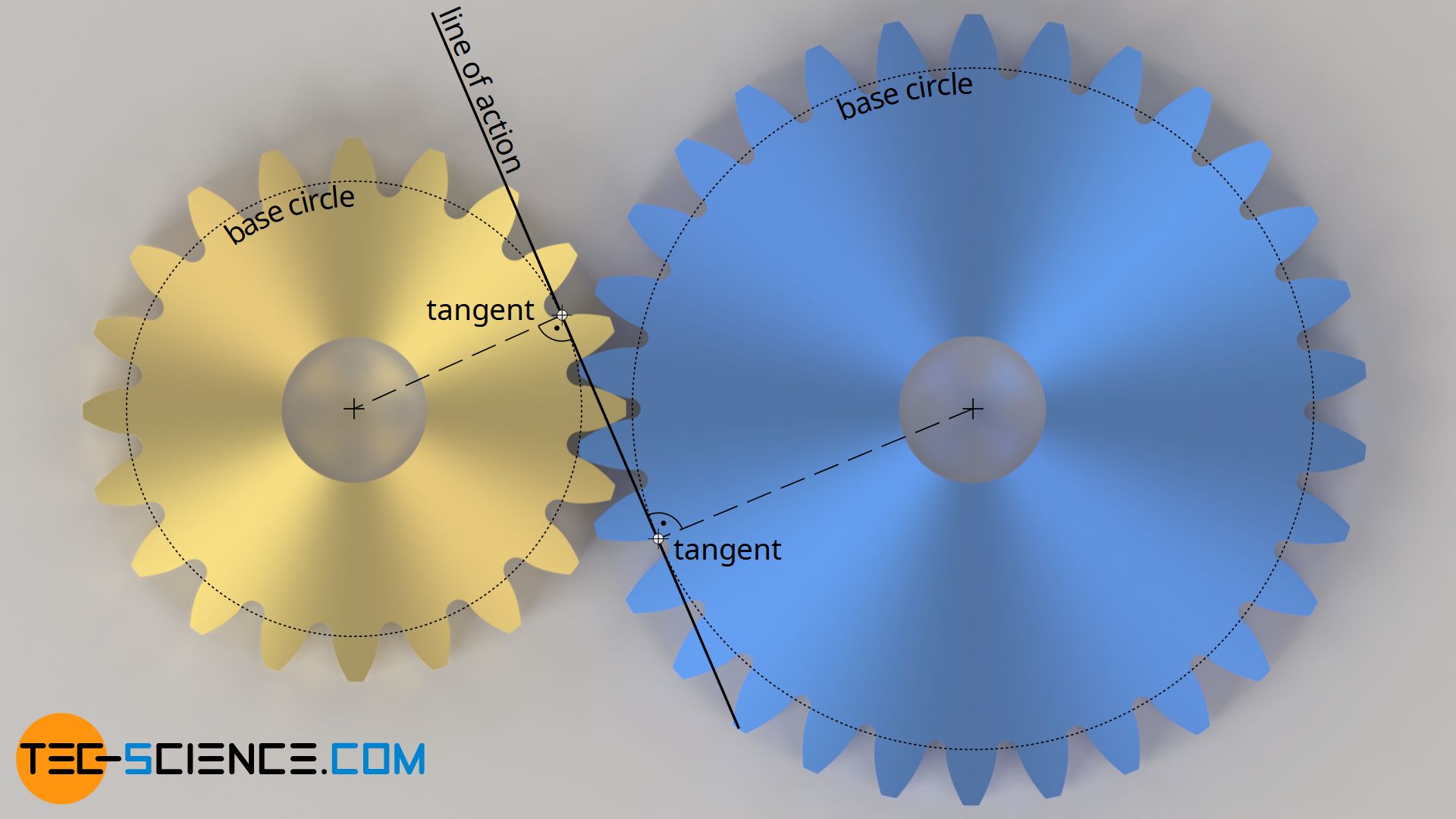
Due to the special design of the tooth shape of an involute gear (rolling a straight line on a circle), the intersection of two involutes rolling off each other describes a straight line. This situation occurs when two gears are meshing. The involute tooth flanks then slide along a straight line (black line in the animation below). This straight line is also referred to as the line of action or line of engagement. This line of action corresponds in principle to the rolling line for the construction of the involute tooth flanks.
The line of action corresponds to the tangent applied on the base circles of the gears.
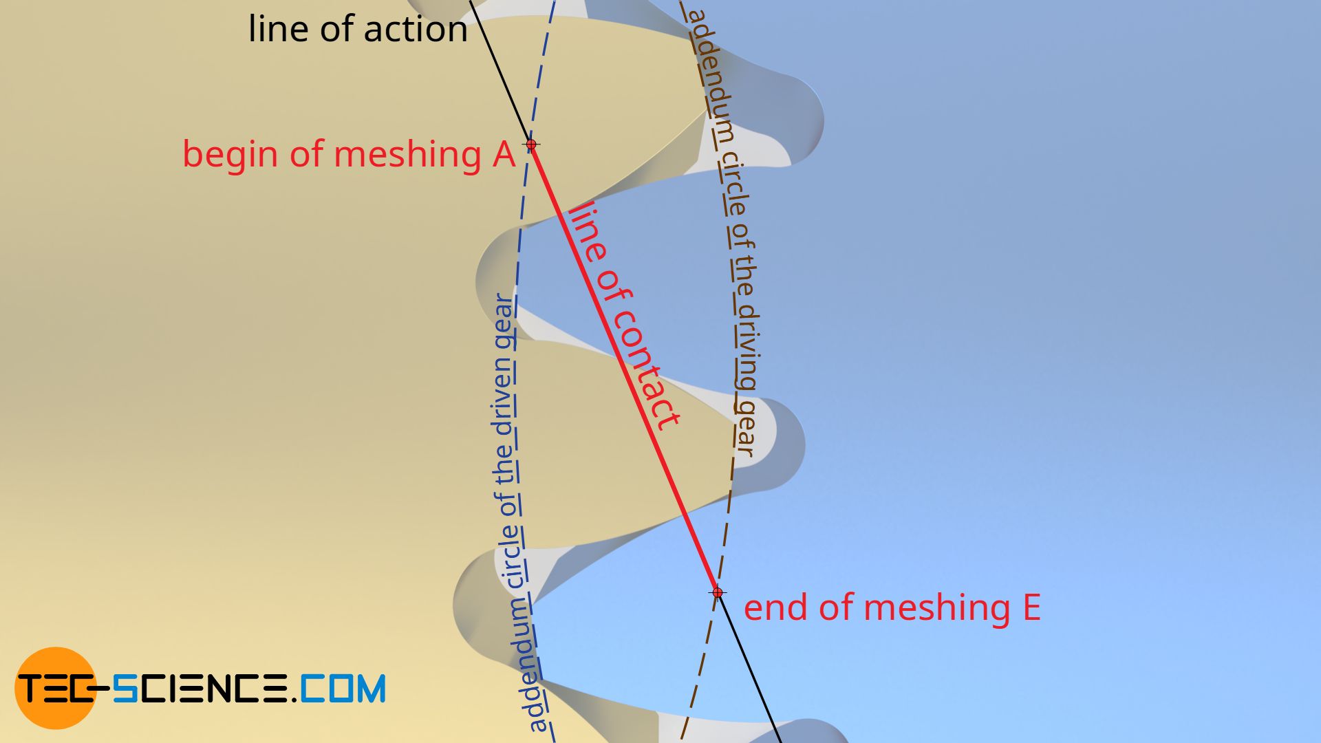
The distance actually covered on the line of action is then called line of contact (red line in the animation above). The line of contact begins at the intersection A between the line of action and the addendum circle of the driven gear and ends at the intersection E between the line of action and the addendum circle of the driving gear.
Pressure angle
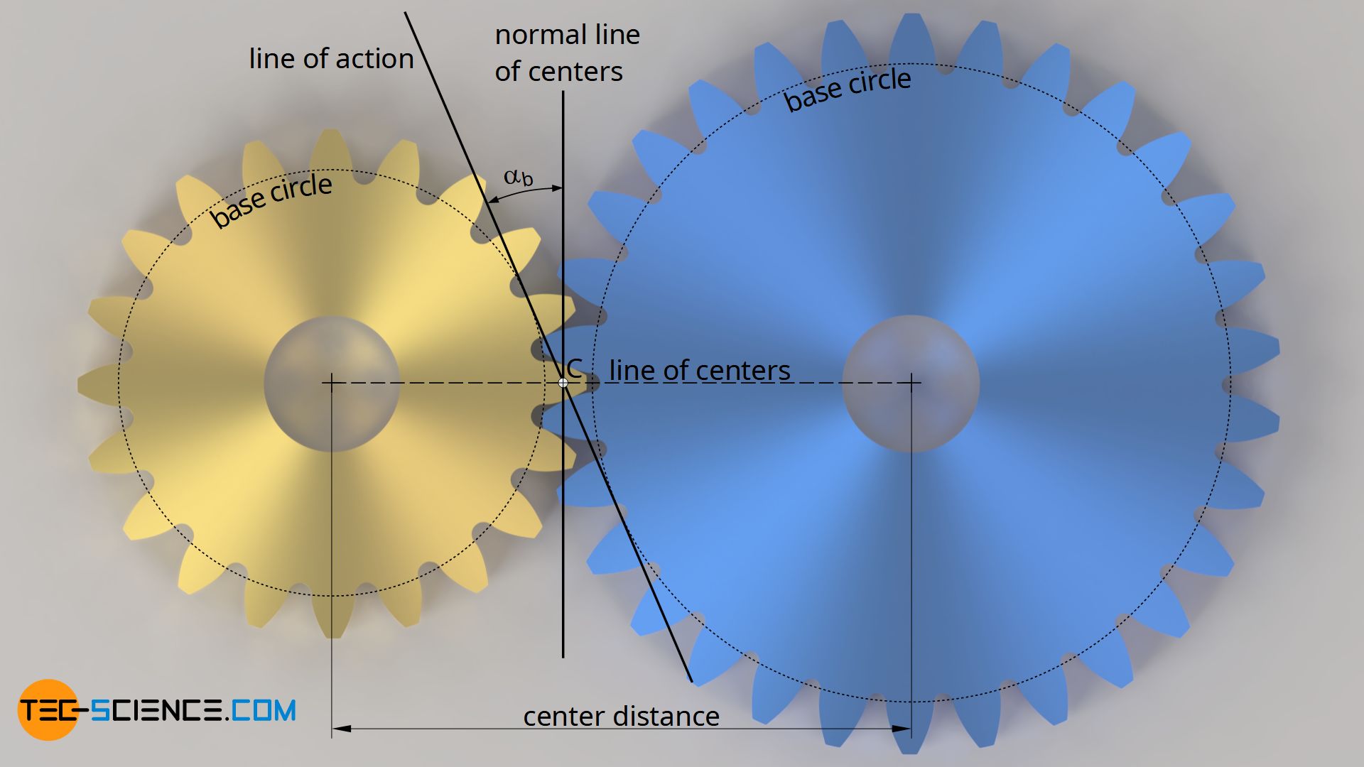
The so-called pressure angle αb refers to the angle between the normal of the line of centers and the line of action. For a standard gear, this pressure angle is set to 20° with backlash-free pairing of the teeth. In this standard state, the pressure angle is also referred to as the standard pressure angle α0 (=20°). In such a case, the center distance is called standard center distance a0 and the resulting operating pitch circles are called standard (reference) pitch circles.
This standardization of the pressure angle α0 is particularly important for the tool geometry in gear manufacturing, since the flank angle of the rack-shaped cutting tool (hob) depends on it. For example, a standard pressure angle of 20° means that the flanks of the hob must also be inclined by 20° to produce the tooth flanks. The tooth shape is thus decisively determined by the standard pressure angle. For more information see article Geometry of involute gears.
The standard pressure angle will be automatically obtained for non-profile shifted gears during backlash-free pairing. However, if the center distance changes or gears with profile shifts are used, the pressure angle will change and then differ from the standard pressure angle. The pressure angle actually resulting during operation is called the operating pressure angle αb (the index b is used because the line of action to which the operating pressure angle refers results as a tangent to the base circles of the gears).
Changing the pressure angle is ultimately associated with a direct change in the line of action and thus in the line of contact. If the center distance differs from the standard center distance, then there is no backlash-free pairing of the gears and the line of contact is shortened (see dark blue gear in the animation below).
Base pitch and contact ratio
In order to ensure continuous power transmission between the flanks of two gears, it is important to ensure that at least one pair of teeth is always meshing with each other on the line of contact. This is not always the case if the center distances are, for example, too large and the line of contact ist thus shortened (see animation above)!
Ideally, the second pair of teeth already engages as long as the first pair of teeth has not yet left the line of contact, i.e. there are even two or more pairs of teeth in contact at the same time. Accordingly, the circumferential forces are distributed over several teeth, which means a reduction of the individual tooth loads. This reduces the risk of tooth breakage.
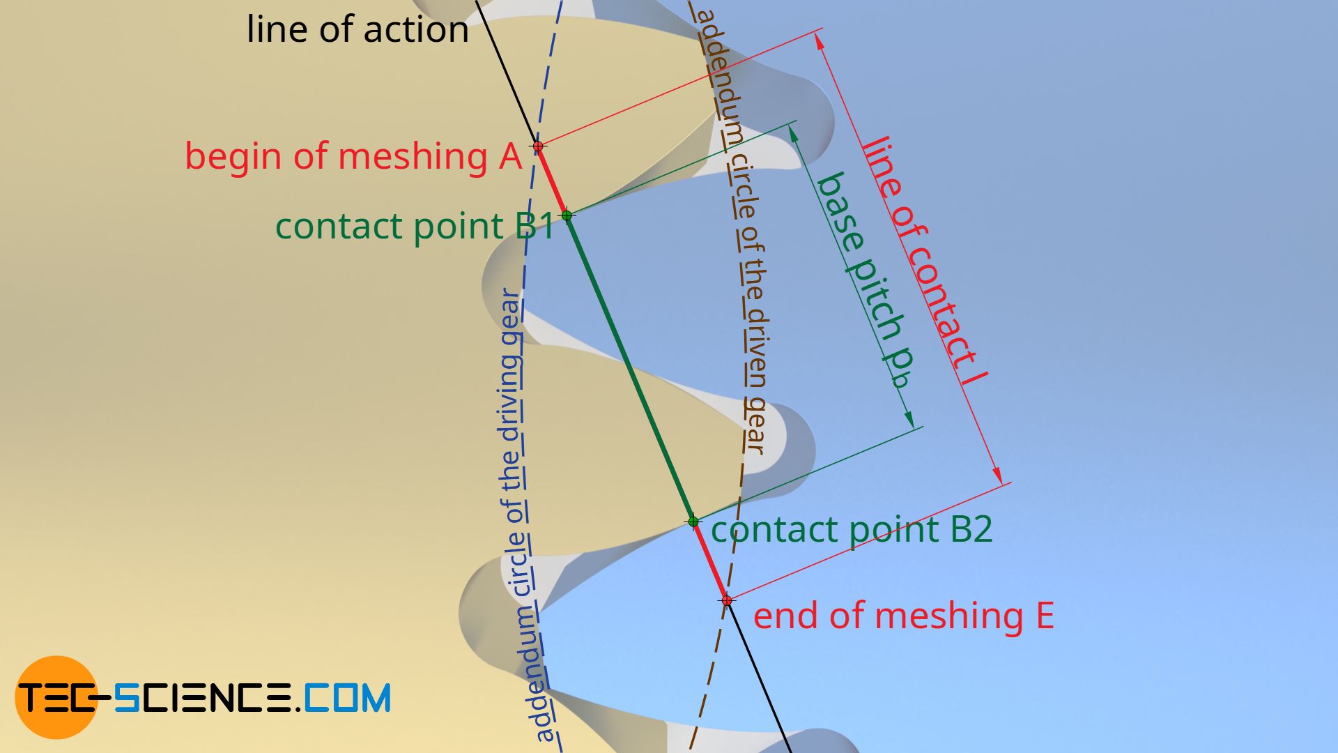
The distance between two adjacent contact points B1 and B2 on the line of contact l is called the base pitch pb.
The base pitch pb is the distance between two flanks on the line of contact.
For continuous power transmission, the base pitch must therefore always be smaller than the line of contact (pb < l). The ratio of the line of contact and the base pitch is also called the contact ratio ε:
\begin{align}
&\boxed{\epsilon = \frac{l}{p_b}} \ge 1 \\[5px]
\end{align}
The contact ratio must therefore always be greater than 1; usually in the range of 1.2 for spur gears. With a large number of teeth and a small module, the contact ratio becomes particularly large, resulting in low noise emissions!
The contact ratio indicates how many teeth are in mesh simultaneously on the line of contact. The greater the contact ratio, the greater the forces that can be transmitted and the lower the noise level!
Influence of the center distance on the base pitch and the contact ratio
Due to the special construction of the involute for the shape of the tooth flanks, these are always perpendicular to the line of action. One can simply imagine the line of action as the rolling line with which the involute shape is constructed. Then it becomes immediately clear that the line of action is always perpendicular to the involute and thus perpendicular to the tooth flank.

In general, the base pitch corresponds to the perpendicular distance between two adjacent tooth flanks of a gear or the perpendicular distance between adjacent involutes!
The base pitch corresponds to the perpendicular distance between two adjacent tooth flanks of a gear!
Since the distance between the tooth flanks and thus the base pitch is a constant parameter of a gear, the base pitch does not change even if the center distance changes. Only the line of contact is shortened when the center distance is increased, so that the contact ratio is reduced. If the center distance changes too much, the contact ratio can be less than 1 and the tooth flanks can therefore partially lose their contact with each other.
The base pitch does not change when the center distance is changed, only the line of contact and thus the contact ratio is shortened when the center distance is increased.
The term “base pitch”
Of course, there is a reason why the distance between the flanks on the line of contact is called the base pitch. Because of the special design of the involute (rolling off the line of action (as the rolling line) on the base circle), this base pitch ultimately corresponds to the pitch of the teeth on the base circle.
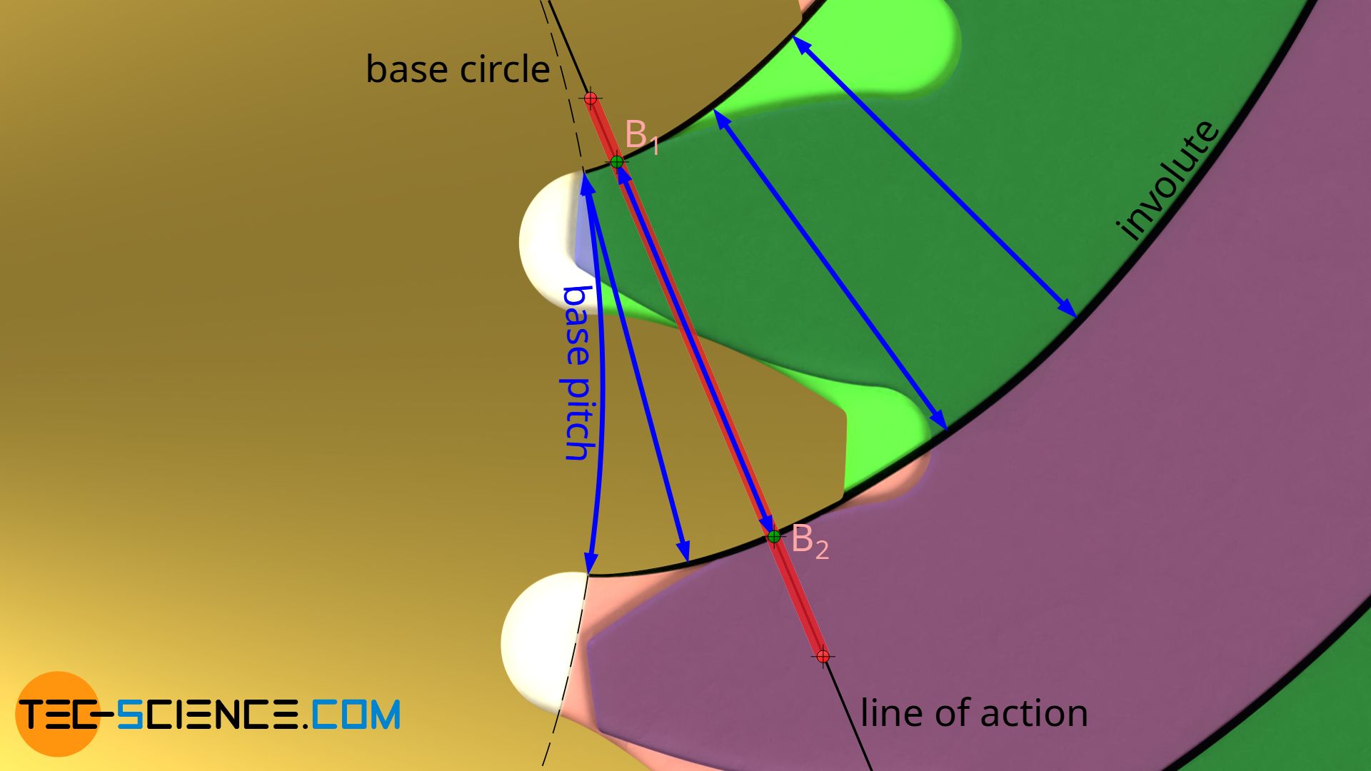
The base pitch corresponds to the arc-shaped distance between two adjacent flanks on the base circle!
Influence of the center distance on the transmission ratio
When two gears mesh, the direction of the force corresponds to the normal at the contact point of two tooth flanks. In the case of involute gears, this corresponds exactly to the line of action. No matter how the line of contact changes with a change of the center distance, the force therefore always remains tangential to the base circle and is therefore always perpendicular to the base circle radius.
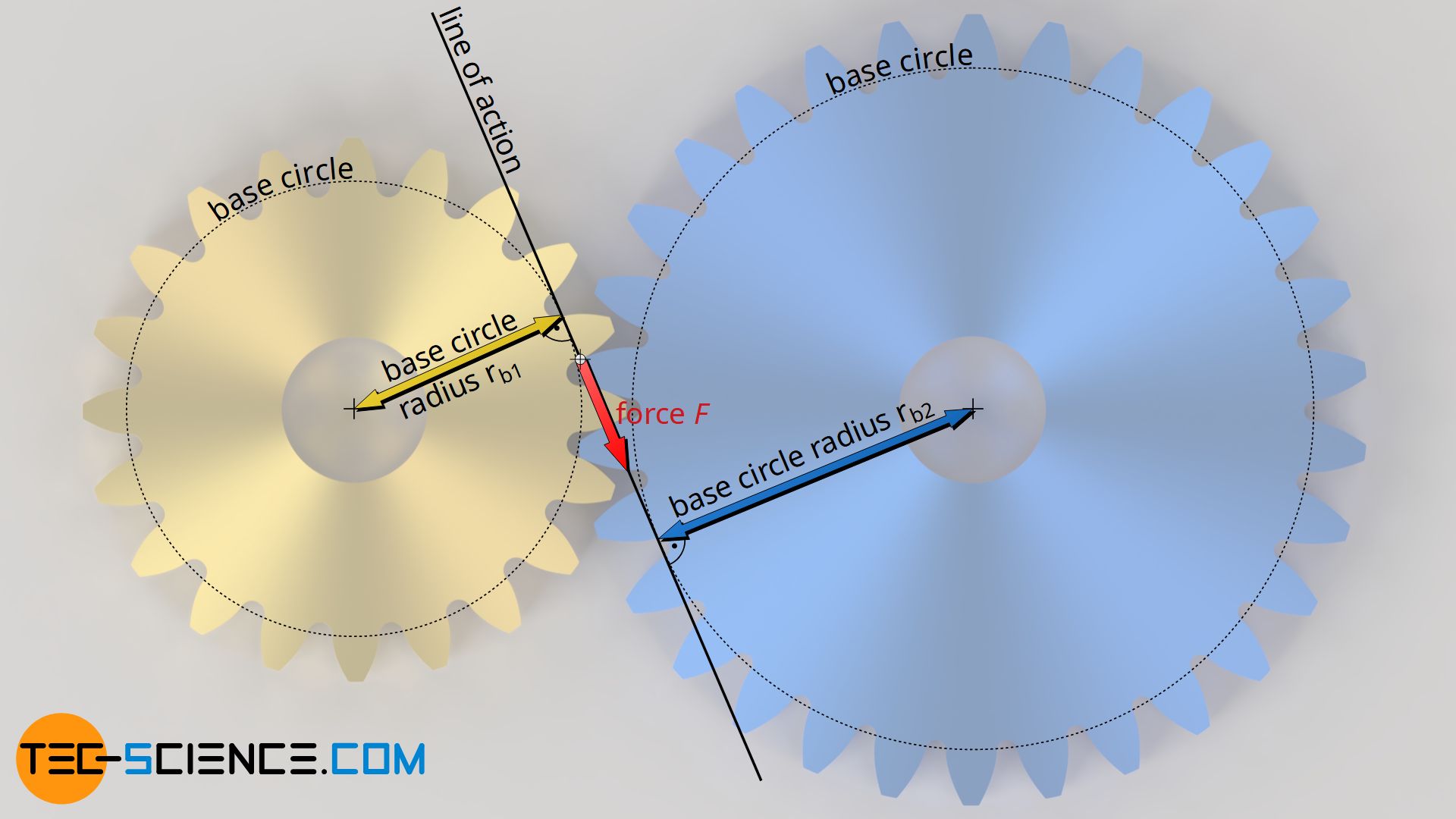
The base circle itself does not change for gears, even with changes in center distance, since the base circle determines the shape of the involute tooth flank. Conversely, this means that the base circle is clearly predetermined by the shape of the tooth. Since the tooth shape does not change when the center distance changes, the base circle or the base circle radius always remains constant.
Since the force is always perpendicular to the base circle radius even when the center distance is changed, the torque does not change. This also means that the transmission ratio of involute gears is independent of the center distance (for example, this is not the case with cycloidal gears). For this reason – and because of the relatively simple manufacturing process – involute gears are mainly used in mechanical engineering. This statement must of course be limited if the center distance becomes so large that the flanks lose contact with each other.
The transmission ratio of involute gears is independent of the center distance!
The constant transmission ratio applies not only to the torques but also to the speeds. This means that if the center distance changes, there is no change in the speed at the output wheel! Because the mechanical power results from the product of rotational speed (angular velocity) and torque. If the torque does not change when the supplied power is constant, then the speed must also remain constant. Otherwise, this would contradict the principle of energy conservation.
Pitch point and operating pitch circle
The tooth flanks of involute gears generally slide onto each other during meshing, only at the so-called pitch point C there is no sliding but pure rolling. This means that the circumferential speeds of both gears are identical at this pitch point. One can imagine the gears at this point as pitch cylinders that roll onto each other.
The corresponding diameters are then called operating pitch diameters. Before and after the pitch point, relative motions take place between the tooth flanks. These sliding motions are also the reason why gears generally have to be lubricated in order to minimize wear on the flanks.
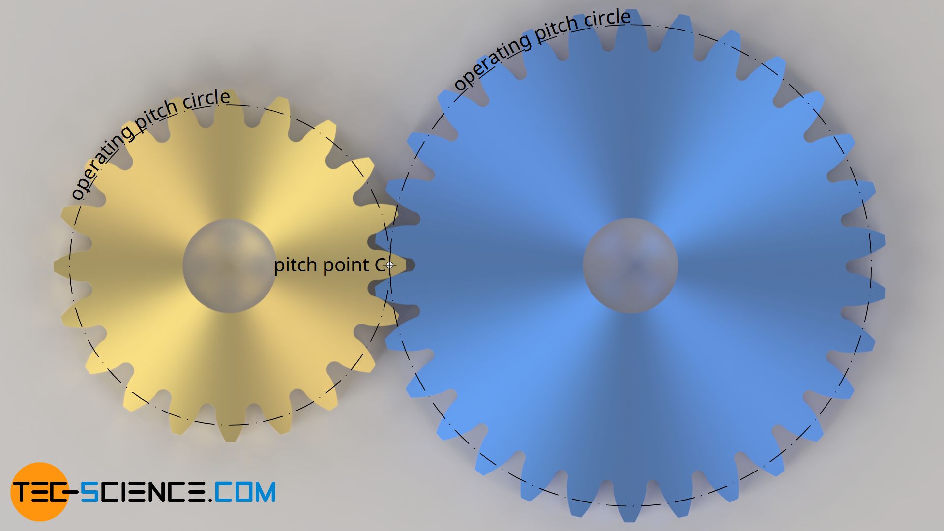
The tooth flanks of the gears generally slide onto each other; pure rolling occurs only at the pitch point! The corresponding operating pitch diameters indicate the diameters of imaginary (pitch) cylinders that roll onto each other without sliding!
The pitch point does not lie at the center of the line of action, as is often claimed, but is located at the intersection between the line of action and the line of centers.
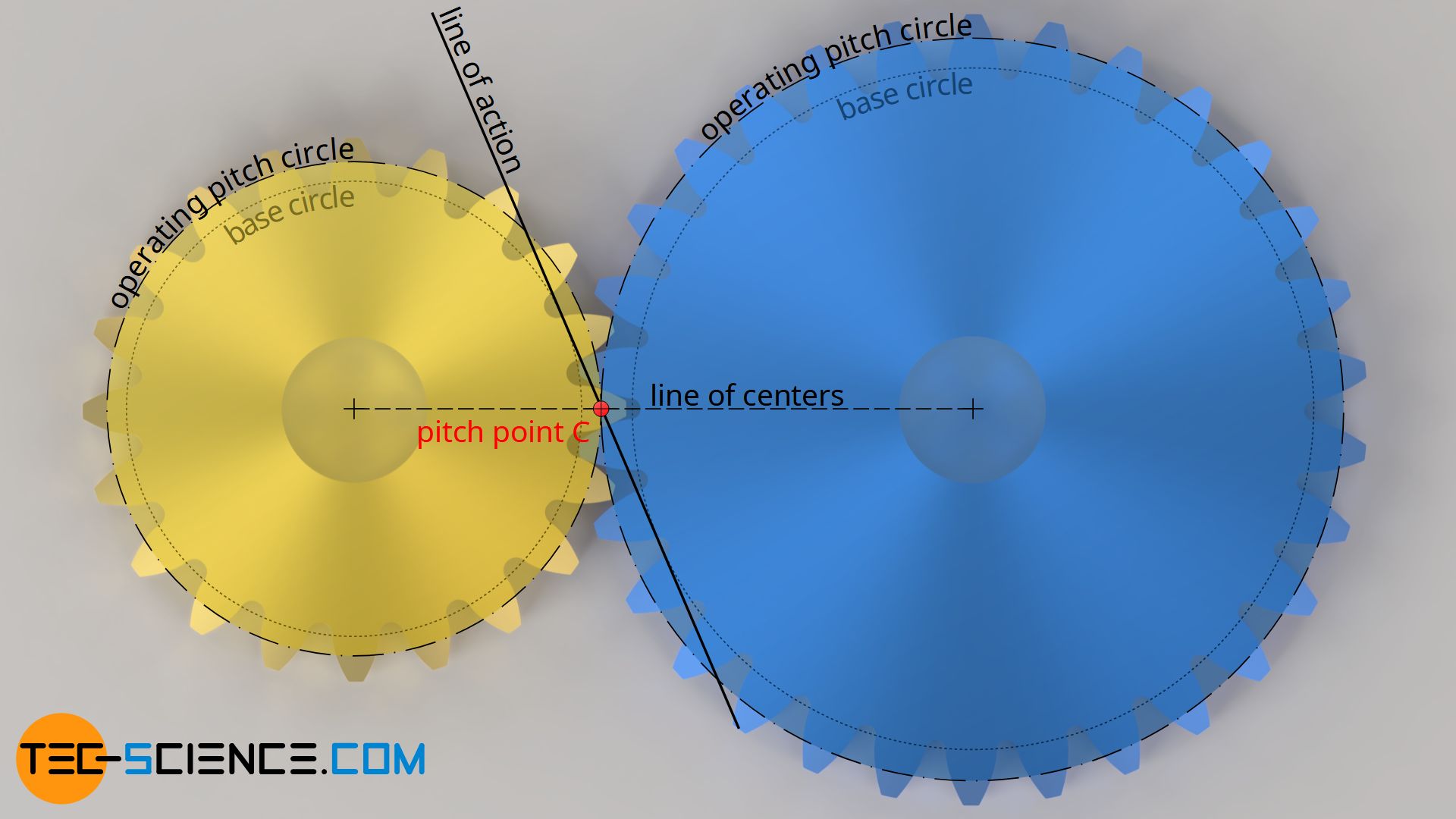
In contrast to the standard (reference) pitch diameter, the operating pitch diameter is not a constant parameter of a gear, but depends on the center distance. If the center distance is changed, the inclination of the line of action (i.e. the pressure angle) and thus the position of the pitch point also changes. This also changes the operating pitch circles. The operating pitch diameters increase with increasing center distance.
The operating pitch circles of two meshing gears depend on the center distance: The larger the center distance, the larger the operating pitch diameter!
Calculation of the operating pitch diameter
As already explained in detail in the article Construction and design of involute gears, the standard reference pitch circles of gears are specially defined circles to which the circular pitch is related. The standard pitch circles are only identical with the operating pitch circles if the gears are paired backlash-free and the operating pressure angle αb thus corresponds to the standard pressure angle α0.
If, however, the pressure angle changes due to a change in center distance, the operating pitch circles differ from the standard pitch circles. The operating pitch circles can be determined using the operating pressure angle αb, as shown below.
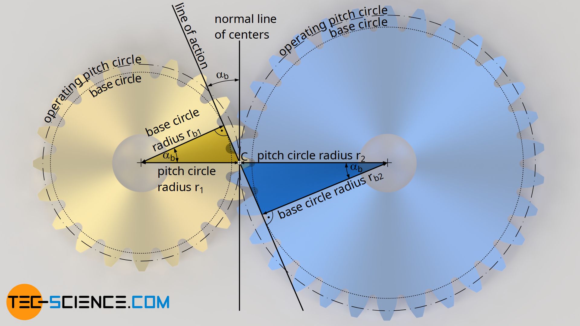
As already explained in the previous section, the base circles do not change even if the center distance or the pressure angle is changed. Thus the same base circle radius rb applies to the standard pressure angle α0 with the corresponding standard pitch circle radius r0 as well as to any operating pressure angle αb with the corresponding operating pitch circle radius r.
Both radii and diameters are related by the cosine of the pressure angle (see yellow and blue triangles in the figure above). In this way, the standard pitch diameter d0 can be used to determine the operating pitch diameter d by means of the operating pressure angle αb as follows:
\begin{align}
&r_b(\alpha_b)=r_b(\alpha_0) \\[5px]
&r \cdot \cos(\alpha_b) = r_0 \cdot \cos(\alpha_0) \\[5px]
&\tfrac{d}{2} \cdot \cos(\alpha_b) = \tfrac{d_0}{2} \cdot \cos(\alpha_0) \\[5px]
&\boxed{d = d_0 \cdot \frac{\cos(\alpha_0)}{\cos(\alpha_b)}} ~~~\text{with } \alpha_0 = 20° ~\text{for a standard gear} \\[5px]
\end{align}
Note that the standard pitch diameter d0 and the standard pressure angle α0 are fixed parameters of a gear and do not change during operation! In a nutshell, the standard pressure angle describes the shape of a tooth flank and the standard pitch diameter the size of the gear. Since these parameters of the gear are known in advance, the corresponding operating pitch diameter d can be determined directly using the operating pressure angle αb.
At this point it becomes clear once again that the operating pitch circle obviously only corresponds to the standard pitch circle if the operating pressure angle is equal to the standard pressure angle (αb=α0). In many cases, however, this is not the case in practice, so that the operating pitch circle differs from the standard pitch circle. This applies in particular to corrected gears (gears with a profile shift).
Fundamental law of gearing
It has already been explained in the section “Influence of the center distance on the transmission ratio” that the transmission ratio of involute gears is independent of the center distance. Such an independence of the transmission ratio should not only apply to changes in center distance, but should also be present in principle.
If, for example, the tooth flanks of an involute gear differ from the ideal involute shape, the force direction of the tooth flanks can change during meshing on the line of action. This also changes the lever arm perpendicular to the force and thus the torque. This in turn leads to torque and speed fluctuations. In such a case, no constant transmission ratio is obtained.
The flank shape thus has a decisive influence on the constancy of the transmission ratio. For this reason, the first question to be asked with all tooth forms for gears is how they must be formed so that a constant transmission ratio is present during operation. The answer to this question can be reduced to the following fact:
For a constant transmission ratio, the normal at the point of contact of two tooth flanks must run at any time through the pitch point (fundamental law of gearing)!
This statement is also referred to as the fundamental law of gearing. If the direction of the force were not to run constantly through the pitch point, this would lead to a permanently changing lever arm and thus cause torque fluctuations. The transmission ratio would therefore not be constant.


")

