Learn more about the different manufacturing processes for cutting involute gears in this article.
Gear hobbing
Involute gears are often manufactured by hobbing. The cutting edges of a hob are straight-flanked and wrap spirally around the milling tool (similar to the thread of a screw). The cross-sectional profile of a hob is equal to that of a rack!
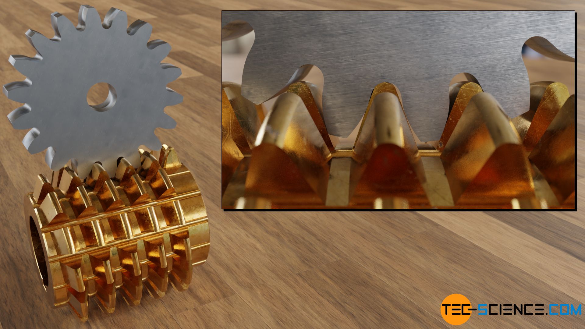
As the gear rotates, the teeth of the hob, which also rotate, continue to mill inwards into the gear over time until the final depth is reached. During one rotation of the hob, the gear moves forward by one tooth. In this respect, the pitch of the cutters corresponds exactly to the tooth pitch of the gear. Gear and hob form a kind of “worm gear” in their motion sequence.
The rotational speed between gear and hob must therefore be matched to each other so that the teeth can form correctly. The number of teeth on the gear reflects the ratio of the rotational speeds. When manufacturing a gear with 18 teeth, the rotational speed of the hob must therefore be 18 times higher than the speed of the gear.
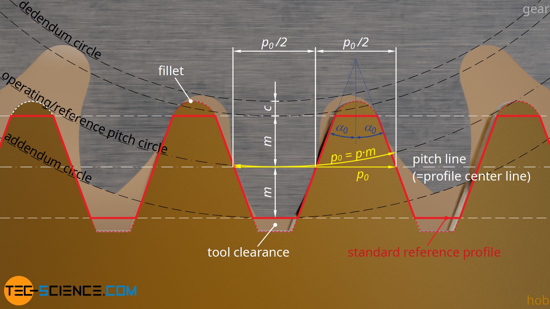
The geometry of the rack-shaped tool profile depends on the desired flank profile of the gear tooth. The tool flanks are inclined against the vertical by the standard pressure angle α0. The actual tool profile is created from the so-called standard reference profile after consideration of the root fillet and the clearance c. The center line of the profile corresponds to the pitch line.
The cutting performance of gear hobbing is very high, so that especially very thick gears can be produced in a relatively short time. However, this process cannot be used to produce internal gears. For this purpose, for example, gear shaping can be used, which will be described in more detail in the next section.
The basic relationship between a gear and a rack (“tool profile”) is shown in the figure below. It is shown that the perpendicular distance between the involutes for all gears with the same module always corresponds to the perpendicular distance between two adjacent flanks. This distance ist called base pitch pb and corresponds to the distance between two contacting flanks in mesh with a mating gear (or rack).

Furthermore the figure shows, that the base pitch pb is directly related to the circular pitch p0 on the reference pitch circle by the standard pressure angle α0. Note that the circular pitch p0 is identical for all gears with the same module, otherwise they could not mesh. For this reason, the circular pitch p0 of the rack also corresponds to the circular pitch of the gears.
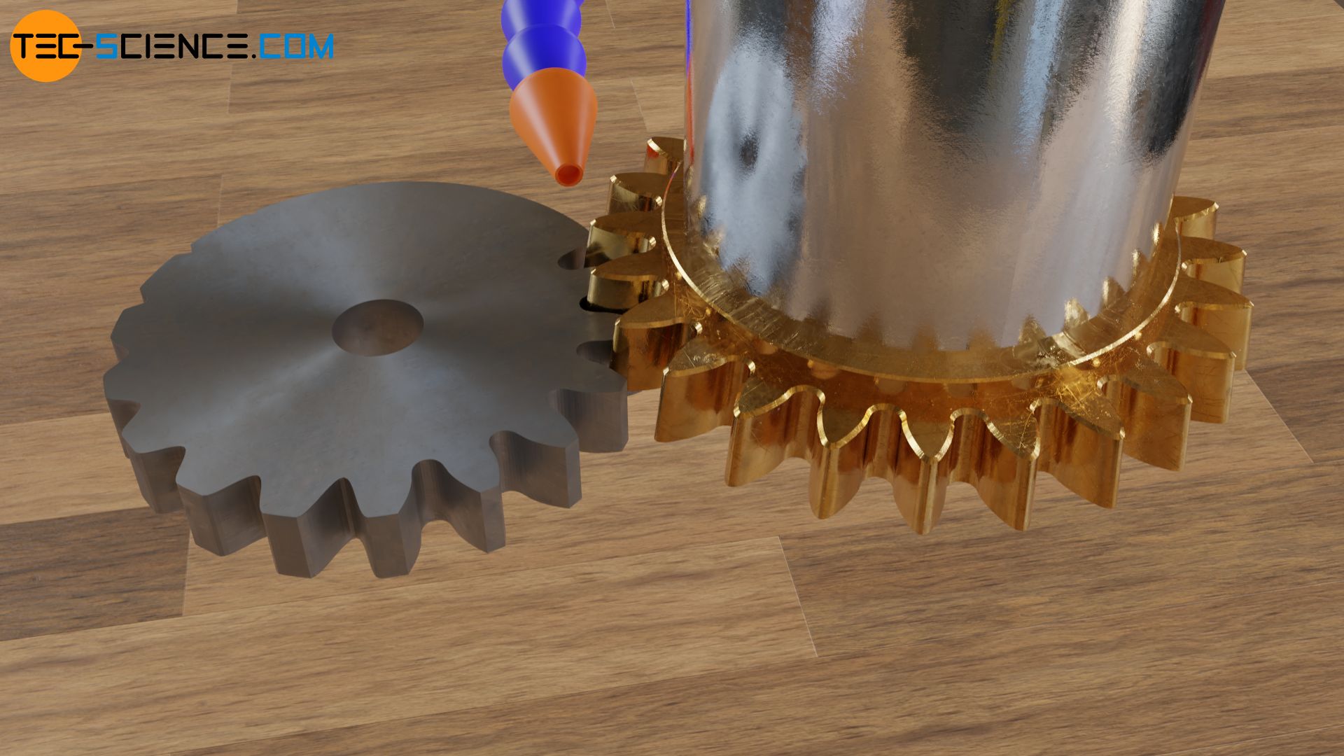
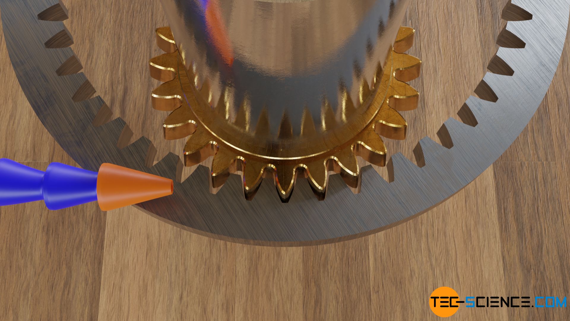
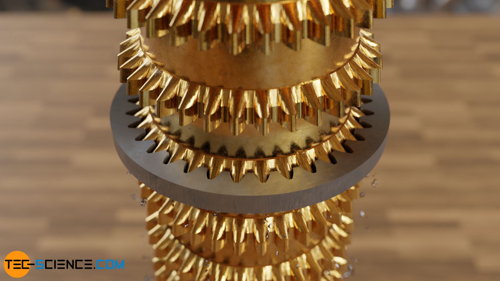
Therefore, one single rack-type hob can be used to produce gears with any number of teeth and then paired with each other. Thus, a 6-tooth gear (red) is produced with the same tool as an 18-tooth gear (green) or a 9-tooth gear. This applies not only to gear hobbing, but also to gear shaping and gear planning.
Note: As the above animation shows, if the number of teeth is too low, the teeth are “undercut” during the manufacturing process and thus weakened. Such an undercut – and how it can be avoided even with a small number of teeth – is described in more detail in the article Profile shift.
Gear shaping
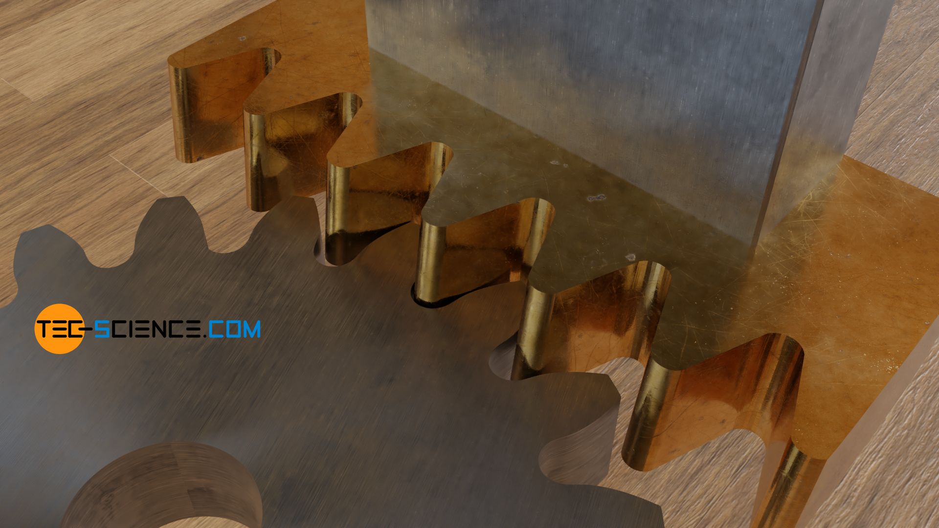
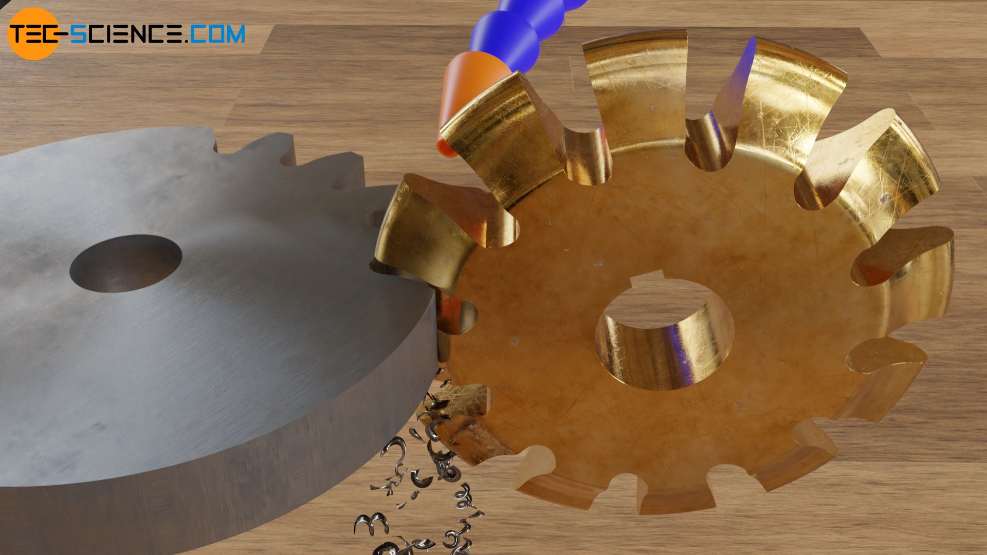
Gears can be produced not only by hobbing but also by shaping. In contrast to hobbing, however, shaping is performed by a translational reciprocating motion of the tool.
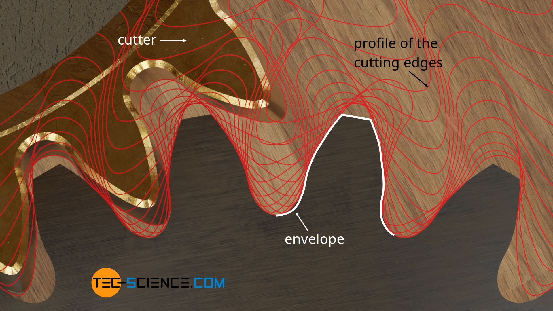
With shaping the cutting edges are arranged like the teeth of a gear on the circumference of the tool. The backward tapered cutting edges have involute flanks. The tool reciprocates in axial direction during the cutting process. During the cutting stroke, the cutting edges push into the gear blank and remove material. During the return stroke (back stroke), the tool is retracted slightly to prevent collision with the gear blank. The reciprocating motion of the tool is a rotating motion of the tool and workpiece superimposed. The tool rolls on the gear blank in a cutting manner. The tool can actually be regarded as a “gear with cutting edges”.
In contrast to gear hobbing, gear shaping can also be used to manufacture internal gears. Shaping can also be used to produce helical gears. For this purpose, the tool is simply inclined by the amount of the helix angle.
With gear shaping internal gears can be produced!
Hobbing, shaping and planing (described in the next section) are ultimately based on the same principle, which can be illustrated using the example of gear shaping: The cutting tool roll on the pitch circle of the gear blank perpendicular to the cutting motion. The envelope of the cutting edges then creates an involute tooth shape.
Gear planning with a rack type cutter
Instead of a “pinion-shaped” tool as is the case with gear shaping, a rack-shaped tools can also be used. In terms of kinematics, the tool and workpiece form a kind of “rack and pinion gear“. One speacks of planning with a rack type cutter (straight-flanked cutting edges). The required clearance angle at the cutting edges is again achieved by the fact that they taper to the rear.
During the cutting stroke, the cutting edges removes material from the gear blank and is then lifted slightly off the workpiece during the return stroke to avoid collision. As is usual with a “rack and pinion gear”, both the gear blank and the rack type cutter continue to move during planing. Since the rack type cutter usually has fewer cutting edges than the teeth on the gear are to be produced, the cutter must be reset after one pass.
The rack shaped cutter can also be used to produce helical gears. For this purpose, the cutter only has to be set at an angle corresponding to the helix angle. In contrast to gear shaping with a pinion type cutter, whose cutting edges are involute-shaped, the rack type cutter has straight flank cutting edges. Rack type cutters can therefore be produced much more easily and thus more cost-effectively. However, internal gears cannot be produced. Planing with a rack type cutter is mainly used for very large gears. The cutting performance is relatively low compared to gear hobbing.
Gear form cutting with a disc cutter
With form cutting, the cutting edges on the milling tool have the shape of the tooth space. The milling tool mills each tooth space individually before the gear blank is rotated one tooth space at a time. The teeth of the gear are produced exclusively by the rotational motion of the tool. During the machining process, there is therefore no superimposed rotational motion of the gear blank as is the case with gear hobbing, shaping or planing. In the latter three manufacturing processes, the shape of the tooth is created by the envelope of the cutting edges; with form cutting or broaching (explained in the next section), however, the tooth shape is created directly by the cutting edge geometry of the tool.
In contrast to hobbing, shaping or planing, the cutting motion of the tool does not have to be matched to the motion of the workpiece. Therefore, form cutting can also be carried out on ordinary milling machines. However, since the tooth spaces have different geometries depending on the size of the gear, a single form cutter can only be used to produce a specific gear. For each module (or diametral pitch) and each number of teeth, separate disc cutters are required, which are relatively expensive due to the individual shape.
Form cutting of gears (milling) can be performed on ordinary milling machines. Special disc cutters are required for each module (diametral pitch) and each number of teeth!
Gear broaching
Broaching is similar to shaping or planing in terms of motion. However, a broaching tool has several cutting edges arranged one behind the other. Each cutting edge takes material and thus successively creates the final shape. If the broaching tool has been completely moved through the workpiece, the final shape is usually already reached. Broaching thus has a high cutting efficiency and is used above all for internal gears.
In contrast to gear shaping or planing, the tooth geometry of the gear is produced directly by the involute shape of the cutting edges of the broaching tool and not by an envelope of the cutting edges. Therefore, only one specific gear can be produced with one broaching tool. For each number of teeth or module, a specific broaching tool is required. Gear broaching is therefore only used in mass production.


")


