Involute function
For the calculation of involute gears, the involute tooth flank must first be described mathematically. The figure below shows the involute belonging to the base circle with the radius rb. A point P on this involute can be described by the angle α, which is spanned between the straight lines GP and GT. The point G corresponds to the center of the base circle and T to the tangent point on the base circle.
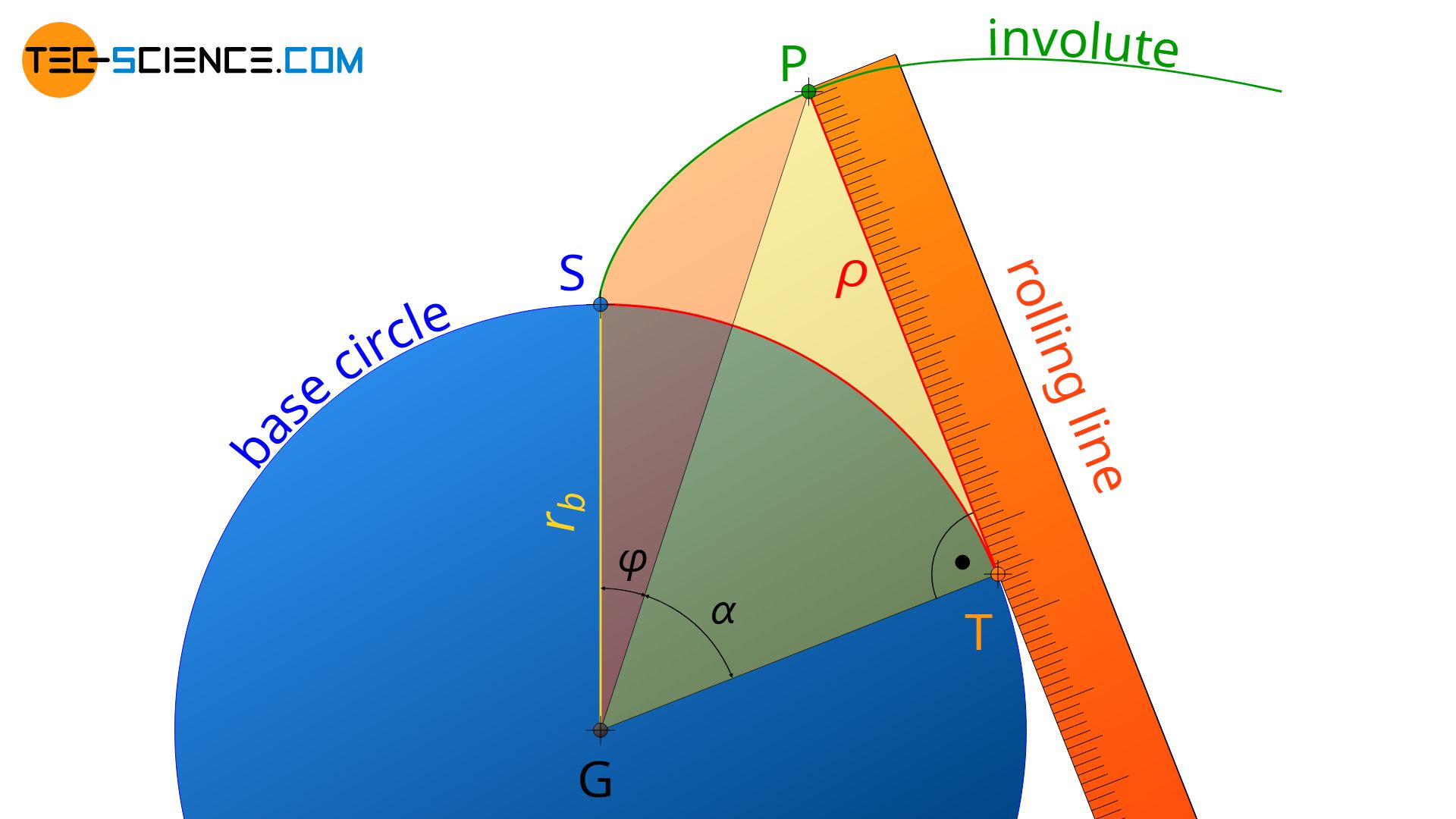
The length of the distance TP is identical to the radius of curvature ϱ of the involute at point P. Furthermore, the distance TP corresponds to the arc distance ST on the base circle, because the rolling line rolls without gliding on the base circle during the construction of the involute:
\begin{align}
\label{1}
\overset{\frown}{ST} &= \overline{TP} \\[5px]
\end{align}
Definition of the involute function
Although the angle α clearly describes a point on the involute, for many geometric calculations the angle φ drawn in the figure above is of greater importance. The angle φ describes the “thickness” of the involute tooth, so to speak.
Using equation (\ref{1}), the following relationship can be established between the angles φ and α:
\begin{align}
\overset{\frown}{ST} &= \overline{TP} \\[5px]
r_b \cdot \left(\varphi + \alpha \right) &= r_b \cdot \tan(\alpha) \\[5px]
\end{align}
\begin{align}
\label{p}
&\boxed{\varphi = \tan(\alpha)-\alpha} \\[5px]
\end{align}
The function resulting from the equation (\ref{p}) is called involute function inv(α). With the involute function many geometric gear parameters can be calculated.
\begin{align}
\label{involute}
&\boxed{\text{inv}(\alpha) = \tan(\alpha)-\alpha} = \varphi ~~~\text{involute function} \\[5px]
\end{align}
All angles for the involute function must always be given in radians!
Operating pressure angle
That the involute angle as well as the pressure angle are denoted by the same greek letter α is no coincidence! The involute angle α in the involute function can be interpreted as the operating pressure angle αb, if the considered point P is located on the operating pitch circle of the gear and thus corresponds to the pitch point C=P!
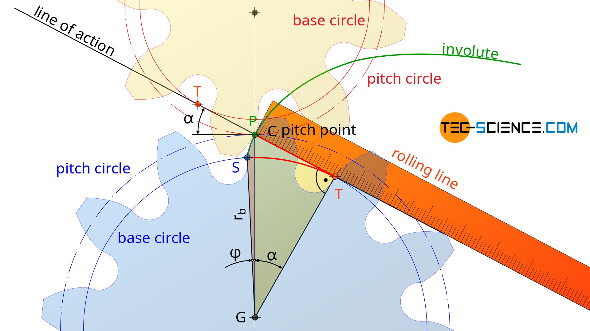
Since the line of action is defined by the tangent to the base circle, which runs through the pitch point C, the distance TP is thus a part of the line of action. The involute angle α thus corresponds to the operating pressure angle αb. If the point P is located on the reference pitch circle of the gear, then the standard pressure angle α0 is obtained!
Calculation of the tooth thickness
The involute function explained in the previous section can be used to determine the tooth thickness s on an arbitrary diameter d of a gear. The figure below shows the geometric relationships: s0 denotes the tooth thickness on the reference pitch circle and r0 the corresponding reference pitch circle radius. The tooth thickness at the considered distance r to the center of the base circle G is denoted by s.
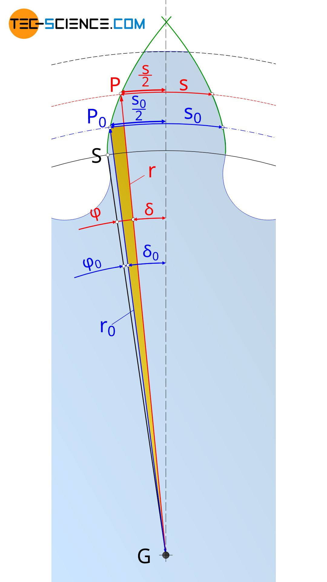
The derivation for the formula to calculate the tooth thickness s is done by the yellow triangle marked in the figure above. The acute angle of the yellow triangle can be determined by the difference between the angles δ0 and δ, whereby the angles are determined according to the definition of radians as “ratio of the arc length to the length of the radius” as follows:
\begin{align}
\label{delta}
\underline{\delta_0} =\frac{\tfrac{s_0}{2}}{r_0}=\frac{s_0}{2 r_0} =\underline{\frac{s_0}{d_0}} ~~~~\text{and}~~~~ \underline{\delta} =\frac{\tfrac{s}{2}}{r}=\frac{s}{2 r} = \underline{\frac{s}{d}} \\[5px]
\end{align}
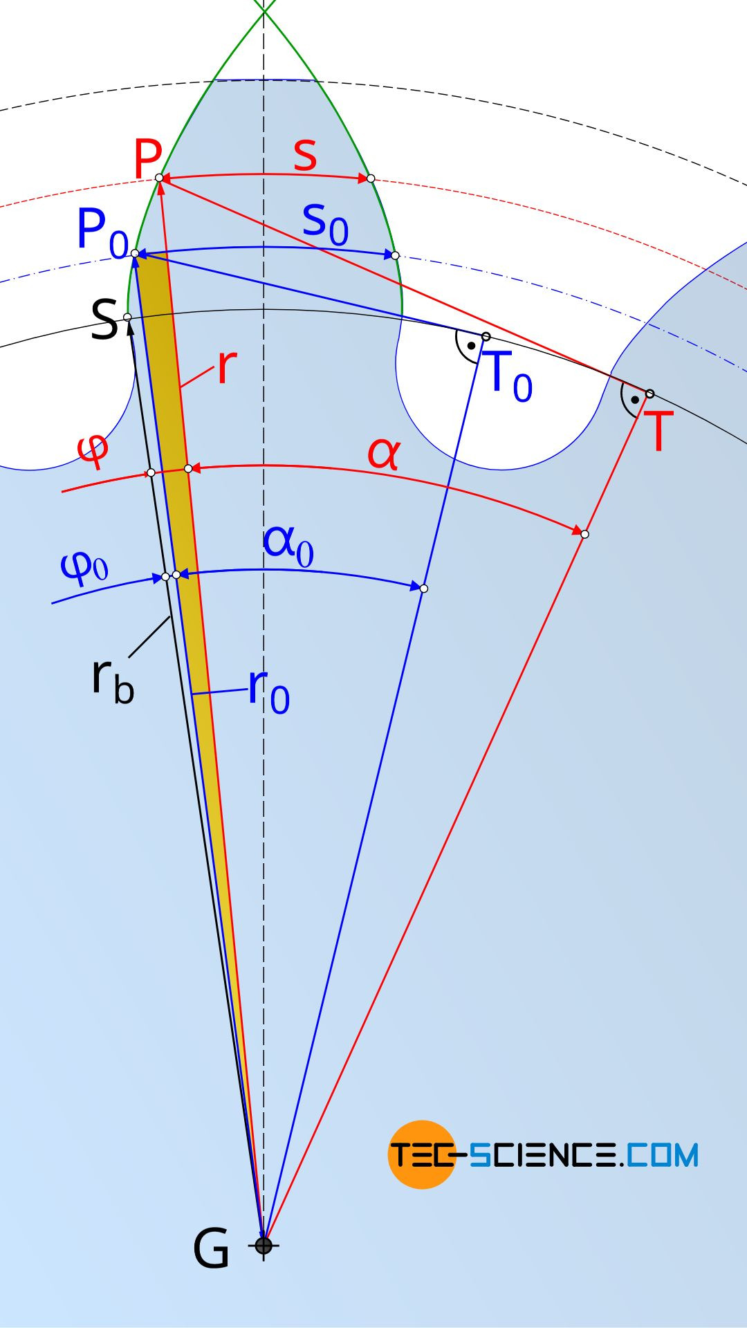
On the other hand, the acute angle of the yellow triangle can also be determined by the difference between the angles φ and φ0. Thus the following relationship applies between the angles δ and φ or δ0 and φ0:
\begin{align}
\delta – \delta_0 &= \varphi_0 – \varphi \\[5px]
\frac{s}{d} – \frac{s_0}{d_0} &= \varphi_0 – \varphi \\[5px]
\end{align}
This equation can now be solved for to the tooth thickness s as a function of the considered diameter d:
\begin{align}
s &= d \left( \frac{s_0}{d_0} + \varphi_0 – \varphi \right) \\[5px]
\end{align}
The angles φ and φ0 correspond to the angles that can be determined using the involute function inv(α) according to equation (\ref{involute}).
\begin{align}
\label{ss}
\underline{s = d \left( \frac{s_0}{d_0} + \text{inv}(\alpha_0) – \text{inv}(\alpha) \right)} \\[5px]
\end{align}
When using equation (\ref{ss}), it must be noted that the tooth thickness s0 on the reference pitch circle depends on a possible profile shift. In the article Profile shift of gears, the relationship between the profile shift coefficient x and the tooth thickness s0 has already been derived (with m as module of the gear):
\begin{align}
&\underline{s_0 = m \cdot \left(\frac{\pi}{2} +2 \cdot x \cdot \tan(\alpha_0) \right) } \\[5px]
\end{align}
In the previous section it was explained that the involute angle α in equation (\ref{ss}) corresponds to the operating pressure angle if the considered point P is located on the operating pitch circle. In the case of the point P0, which is located on the reference pitch circle, the involute angle α0 is then identical to the standard pressure angle α0, which is usually set to α0=0.349 rad (=20°).
Even if the considered point P on the circle on which the tooth thickness s is to be determined does not necessarily correspond to the actual operating pitch circle, any point P can always be regarded as being located on a operating pitch circle. This is because in the end the operating pitch circle only results from the center distance between the two gears in mesh. Since the center distance can be chosen arbitrarily, the operating pitch circle can theoretically always be adjusted so that it runs through the point P.
Due to this consideration a connection between the (operating pitch circle) diameter d of the circle on which the tooth thickness s is to be determined and the (operating pressure) angle α can be established. This connection is made by the standard pressure angle α0 and the corresponding reference pitch circle diameter d0 and has already been derived in the article Construction and design of involute gears. The basis of this relationship is the identical basic circle diameter db which is identical both when considering the operating pitch circle (with the parameters d and α and when considering the reference pitch circle (with the parameters d0 and α0):
\begin{align}
\label{base}
&\overbrace{d \cdot \cos(\alpha)}^{\text{base circle diameter } d_b} = \overbrace{d_0 \cdot \cos(\alpha_0)}^{\text{base circle diameter }d_b} \\[5px]
\label{z}
&\underline{\alpha = \arccos \left(\frac{d_0}{d} \cdot \cos(\alpha_0)\right)} \\[5px]
\end{align}
Note: The angle α in equation (\ref{z}) generally does not correspond to the operating pressure angle αb! In this case, the angle α merely represents an “auxiliary quantity“, which results from the considered diameter d. Only if the diameter d actually corresponds to the operating pitch circle diameter, the angle α will be identical to the operating pressure angle αb. When considering the tooth thickness on the reference pitch circle, the angle α corresponds to the standard pressure angle α0.
With the involute function according to equation (\ref{involute}), the tooth thickness s at an considered circle with the diameter d is completely determined. The necessary equations are summarized again below:
\begin{align}
\label{tooth}
&\boxed{s = d \left( \frac{s_0}{d_0} + \text{inv}(\alpha_0) – \text{inv}(\alpha) \right)} \\[5px]
&\text{with} \\[5px]
\label{tooth0}
&\boxed{s_0 = m \cdot \left( \frac{\pi}{2} + 2 \cdot x \cdot \tan(\alpha_0) \right)} \\[5px]
&\boxed{\text{inv}(\alpha_0) = \tan(\alpha_0)-\alpha_0} ~~~~~\text{with}~~~~~ \boxed{\alpha_0 =0,349 \text{ rad } (=20°)} \\[5px]
&\boxed{\text{inv}(\alpha) = \tan(\alpha)-\alpha} ~~~~~\text{with}~~~~~ \boxed{\alpha = \arccos \left(\frac{d_0}{d} \cdot \cos(\alpha_0)\right) } \\[5px]
\end{align}
The angle α in the equations above is to be considered as an “auxiliary quantity” and generally does not correspond to the operating pressure angle αb!
Calculation of the circular and the base pitch
The circumferential pitch (circular pitch) is the arc distance between two adjacent tooth flanks of the same direction. On an arbitrary circle with a diameter d, the circular pitch p results from the ratio of the circumferential length π⋅d and the number of teeth z:
\begin{align}
\label{p1}
&\underline{p = \frac{\pi \cdot d}{z}} \\[5px]
\end{align}
In case of the reference pitch circle with the diameter d0, the circular pitch p0 is obtained::
\begin{align}
\label{p0}
&\underline{p_0 = \frac{\pi \cdot d_0}{z}} \\[5px]
\end{align}
If equation (\ref{p1}) is divided by equation (\ref{p0}), then the circumferential pitch p0 can be used to establish a connection between an arbitrary diameter d and the resulting circular pitch p:
\begin{align}
&\frac{p}{p_0} = \frac{d}{d_0} \\[5px]
\label{pitch}
&\boxed{p = \frac{d}{d_0} \cdot p_0} \\[5px]
\end{align}
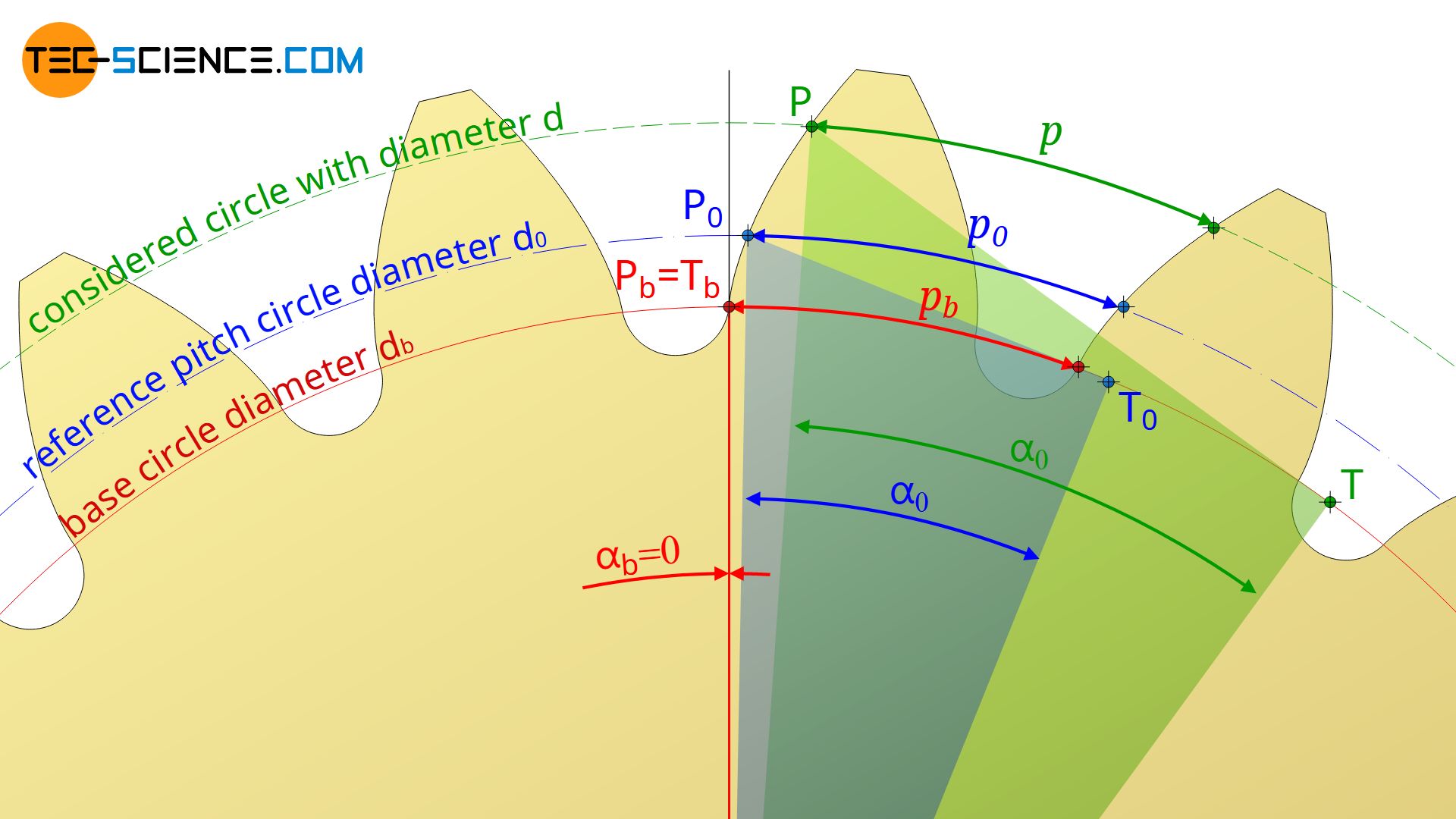
According to equation (\ref{base}), the ratio d/d0 can also be expressed by the involute angle α (corresponding to the diameter d) and the involute angle α0 (corresponding to the reference pitch diameter d0 → standard pressure angle α0). This ultimately means that a point on the involute is considered which is located on the circle with the diameter d (→ α) or on the reference pitch circle with the diameter d0 (→ α0).
\begin{align}
\label{kap}
&\overbrace{d \cdot \cos(\alpha)}^{\text{base circle diameter } d_b} = \overbrace{d_0 \cdot \cos(\alpha_0)}^{\text{base circle diameter }d_b} \\[5px]
\label{d}
&\underline{ \frac{d}{d_0}=\frac{\cos(\alpha_0)}{\cos(\alpha)} } \\[5px]
\end{align}
If equation (\ref{d}) is applied in equation (\ref{pitch}), the pitch p can also be determined as follows:
\begin{align}
\label{pp}
&p = \frac{d}{d_0} \cdot p_0= \frac{\cos(\alpha_0)}{\cos(\alpha)} \cdot p_0 = \frac{\overbrace{\cos(\alpha_0) \cdot p_0}^{p_b}}{\cos(\alpha)} = \frac{p_b}{\cos(\alpha)} \\[5px]
\end{align}
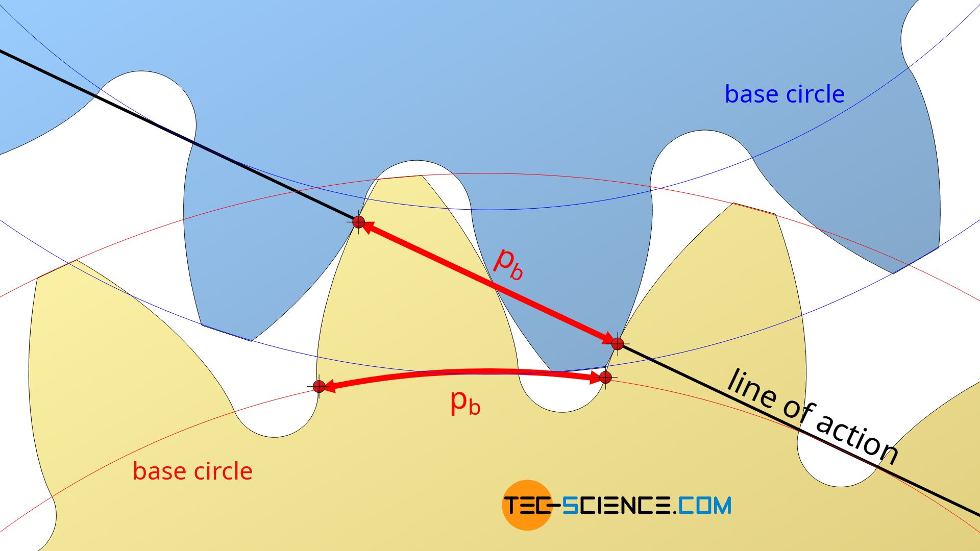
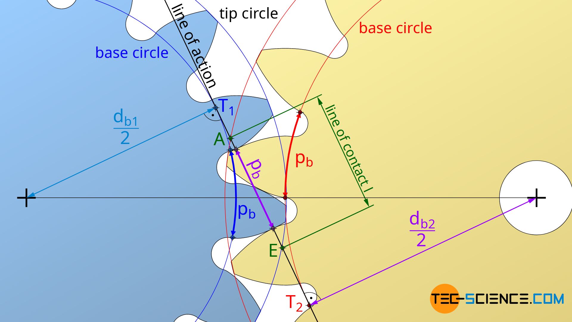
As shown in the article Construction and design of involute gears, the term p0⋅cos(α0) occurring in equation (\ref{pp}) corresponds to the base pitch pb and therefore corresponds the distance between two tooth flanks in contact on the line of action when meshing (see figure below).
The pitch on the base circle corresponds to the distance between two tooth flanks in contact on the line of action!
Since the circular pitch p0 can also be expressed by the module m and the number π (p0=π⋅m, see article Construction and design of involute gears), for the base pitch applies finally:
\begin{align}
\label{pb}
&\boxed{p_b = \pi \cdot m \cdot \cos(\alpha_0)} \\[5px]
\end{align}
Calculation of the center distance
In this section, the center distance of two corrected gears will be determined as a function of the respective profile shift coefficients x.
The starting point is the backlash-free meshing of the two gears, so that the tooth thickness on the operating pitch circle of one gear fits exactly into the tooth space on the operating pitch circle of the mating gear. The sum of the respective tooth thicknesses s1 and s2 thus corresponds to the circumferential pitch p on the operating pitch circles of the gears, which must be identical for both, otherwise the teeth could not mesh.
\begin{align}
\label{ppp}
& \underline{p = s_1 + s_2} \\[5px]
\end{align}
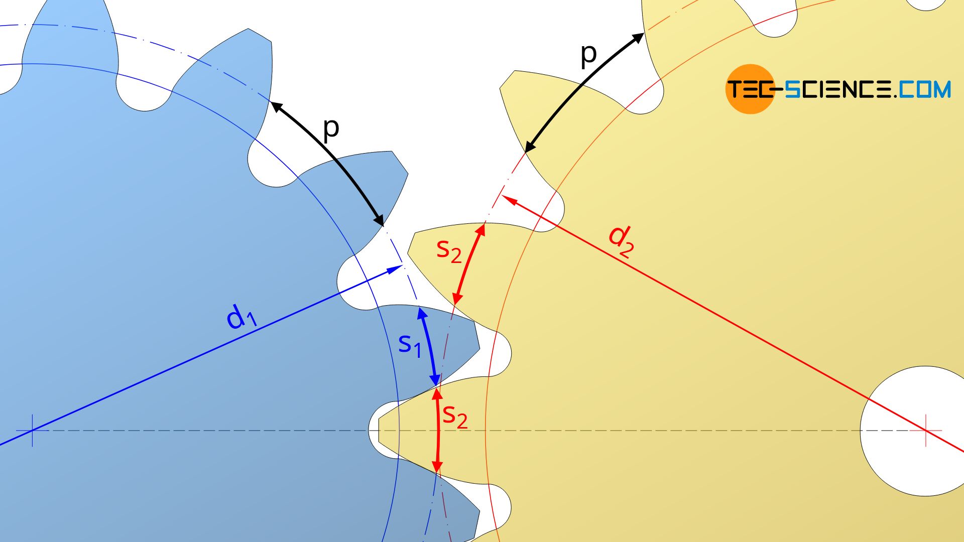
The circular pitch p on the operating pitch circles should not be confused with the circular pitch p0 on the reference pitch circles!
The tooth thickness s on an arbitrary circle with a diameter d can be determined from equations (\ref{tooth}) and (\ref{tooth0}) (parameters with the index “0” refer to the reference pitch circle):
\begin{align}
\label{s}
&s = d \left( \tfrac{s_{0}}{d_{0}} + \text{inv}(\alpha_0) – \text{inv}(\alpha) \right) ~~~\text{with} ~~~ s_0 = m \left( \tfrac{\pi}{2} + 2 x \cdot \tan(\alpha_0) \right) ~~~\text{applies}: \\[5px]
&s = d \left(\tfrac{m}{d_0} \left( \tfrac{\pi}{2} + 2 x \cdot \tan(\alpha_0) \right) + \text{inv}(\alpha_0) – \text{inv}(\alpha) \right) ~~~\text{
with}~~~m=\tfrac{d_0}{z} ~~~\text{applies:} \\[5px]
&\underline{s = d \left(\tfrac{1}{z} \left( \tfrac{\pi}{2} + 2 x \cdot \tan(\alpha_0) \right) + \text{inv}(\alpha_0) – \text{inv}(\alpha) \right)} \\[5px]
\end{align}
Since in this case the involute function inv(α) refers to the operating pitch circles d1 or d2, the involute angle α corresponds to the operating pressure angle αb. For equation (\ref{ppp}) applies finally:
\begin{align}
\notag
p = &d_1 \left(\tfrac{1}{z_1} \left( \tfrac{\pi}{2} + 2 x_1 \cdot \tan(\alpha_0) \right) + \text{inv}(\alpha_0) – \text{inv}(\alpha_b) \right) \\[5px]
\label{pppp}
&+ d_2 \left(\tfrac{1}{z_2} \left( \tfrac{\pi}{2} + 2 x_2 \cdot \tan(\alpha_0) \right) + \text{inv}(\alpha_0) – \text{inv}(\alpha_b) \right) \\[5px]
\end{align}
The operating pitch circle diameters d1 or d2 in equation (\ref{pppp}) can be determined from the definition of the circular pitch p as the ratio of pitch circle circumference π⋅d and the number of teeth z (p = π⋅d/z). Therefore, for the operating pitch circle diameters of the two gears d1 and d2 applies:
\begin{align}
\label{dd}
&d_1 = \frac{z_1 \cdot p}{\pi} ~~~~~\text{and}~~~~~d_2 = \frac{z_2 \cdot p}{\pi} \\[5px]
\end{align}
The equations (\ref{dd}) can now be applied in equation (\ref{ppp}):
\begin{align}
\notag
p = & \tfrac{z_1 \cdot p}{\pi} \left(\tfrac{1}{z_1} \left( \tfrac{\pi}{2} + 2 x_1 \cdot \tan(\alpha_0) \right) + \text{inv}(\alpha_0) – \text{inv}(\alpha_b) \right) \\[5px]
&+ \tfrac{z_2 \cdot p}{\pi} \left(\tfrac{1}{z_2} \left( \tfrac{\pi}{2} + 2 x_2 \cdot \tan(\alpha_0) \right) + \text{inv}(\alpha_0) – \text{inv}(\alpha_b) \right) \\[5px]
\end{align}
Solving this equation for the operating pressure angle αb in terms of the involute function inv(αb) finally leads to:
\begin{align}
\notag
\boxed{\text{inv}(\alpha_b) = 2 \frac{x_1+x_2}{z_1+z_2} \cdot \tan(\alpha_0) + \text{inv}(\alpha_0)} ~~~\text{and} ~~~\boxed{\text{inv}(\alpha_0) = \tan(\alpha_0)-\alpha_0} \\[5px]
\end{align}
Note that the involute function is not an algebraic function and therefore a reverse function cannot be derived. In such a case, the iterative Newton’s method offers a possibility for determining the operating pressure angle.
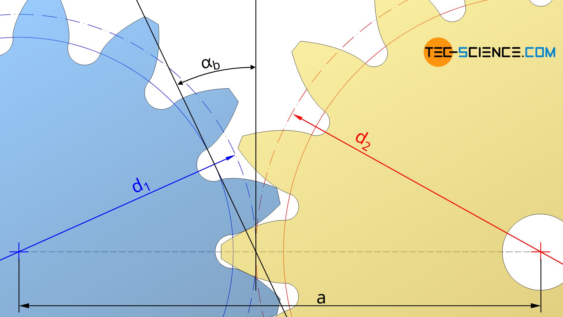
If the operating pressure angle is determined by such an approximation method, then not only the operating pitch circle diameter but also the center distance can be determined, since operating pitch circle diameter d and reference pitch circle diameter d0 are related by the operating pressure angle αb and the standard pressure angle α0 according to equation (\ref{d}):
\begin{align}
&\boxed{d = d_0 \cdot \frac{\cos(\alpha_0)}{\cos(\alpha_b)}} ~~~\text{operating pitch circle diameter} \\[5px]
\end{align}
The center distance “a” results from the sum of the operating pitch circle radii r=d/2:
\begin{align}
a &= r_1+r_2 \\[5 px]
&= \frac{d_1}{2} + \frac{d_2}{2} \\[5px]
& = \frac{d_{0,1}}{2} \cdot \frac{\cos(\alpha_0)}{\cos(\alpha_b)} + \frac{d_{0,2}}{2} \cdot \frac{\cos(\alpha_0)}{\cos(\alpha_b)} \\[5px]
& = (d_{0,1}+d_{0,2}) \cdot \frac{\cos(\alpha_0)}{2 \cdot \cos(\alpha_b)} \\[5px]
& = (m \cdot z_1 + m \cdot z_2) \cdot \frac{\cos(\alpha_0)}{2 \cdot \cos(\alpha_b)} \\[5px]
\end{align}
\begin{align}
\boxed{a = m \cdot( z_1 + z_2) \cdot \frac{\cos(\alpha_0)}{2 \cdot \cos(\alpha_b)}} \\[5px]
\end{align}
Note that gears can also be manufactured with negative profile coefficients. If the sum of the profile shift factors is zero, the same center distance is obtained as in the case of non-corrected gears (called standard center distance a0). The operating pressure angle then also corresponds to the standard pressure angle α0.
Calculation of the profile shift coefficients
The previous section derived the formula for calculating the center distance “a” of two corrected gears:
\begin{align}
\label{a}
&a = m \cdot( z_1 + z_2) \cdot \frac{\cos(\alpha_0)}{2 \cdot \cos(\alpha_b)} \\[5px]
\end{align}
The operating pressure angle αb has to be determined from an approximation method by the involute function:
\begin{align}
\label{inv}
\text{inv}(\alpha_b) = 2 \frac{x_1+x_2}{z_1+z_2} \cdot \tan(\alpha_0) + \text{inv}(\alpha_0) \\[5px]
\end{align}
In some cases, however, the center distance to be achieved is fixed by the gearbox. Then the center distance must be adjusted by a specific profile shift. The animation below shows the change of the center distance by a profile shift of both gears with the profile shift coefficients x1 and x1.
If the center distance “a” is given in advance, then the operating pressure angle αb can first be determined by solving equation (\ref{a}):
\begin{align}
\label{alpha}
&\boxed{\alpha_b= \arccos \left(m \cdot( z_1 + z_2) \cdot \frac{\cos(\alpha_0)}{2 a} \right)} \\[5px]
\end{align}
Equation (\ref{inv}) can then be solved for the profile shift coefficients:
\begin{align}
\text{inv}(\alpha_b) &= 2 \frac{x_1+x_2}{z_1+z_2} \cdot \tan(\alpha_0) + \text{inv}(\alpha_0) \\[5px]
2 \frac{x_1+x_2}{z_1+z_2} \cdot \tan(\alpha_0) &= \text{inv}(\alpha_b) – \text{inv}(\alpha_0) \\[5px]
\frac{x_1+x_2}{z_1+z_2} &= \frac{\text{inv}(\alpha_b) – \text{inv}(\alpha_0)}{2 \cdot \tan(\alpha_0) } \\[5px]
\end{align}
\begin{align}
\label{x}
\boxed{x_1+x_2 = \frac{\text{inv}(\alpha_b) – \text{inv}(\alpha_0)}{2 \cdot \tan(\alpha_0)} \cdot (z_1+z_2)} \\[5px]
\end{align}
If a certain center distance is to be achieved by a profile shift, then the sum of the profile shift coefficients must satisfy the equation (\ref{x}). As long as this is fulfilled, the coefficients can in principle be chosen arbitrarily. However, it makes sense to assign the profile shift
coefficients evenly over the two gears, whereby the sum should not be much larger or smaller than one (i.e. the sum of the profile shifts should be in the range of the module).
The sum of the profile shifts should be in the order of the module of the gears!
The distribution of the profile shift coefficients over the two gears also depends on how pointed the tip of the tooth become with a profile shift. As explained in the article Profile shift, the tip tooth thickness should be at least 0.2 times the module. If this is no longer the case with a profile shift, the tip circle must be shortened. Such a tip shortening will be discussed in more detail in the next section.
Calculation of the tip shortening
In the article Profile shift it was shown that a profile shift is connected with an increase in the tip diameter da and the root diameter dd by the amount of the (positive) profile shift:
\begin{align}
&\boxed{d_a = m \cdot (z+2x+2) } \\[5px]
\label{f}
&\boxed{d_d = m \cdot (z+2x-2) -2c } \\[5px]
\end{align}
In equation (\ref{f}), z denotes the number of teeth, m the module, x the profile shift coefficient and c) the manufacturing tip tooth clearance. The manufacturing tip tooth clearance results from the tool profile during gear cutting.
The manufacturing tip tooth clearance c must not be confused with the operating tip tooth clearance cb, which actually results in operation when two gears are in mesh! It has already been explained in the article Profile shift that the backlash-free meshing of corrected gears results in a reduction of the tip tooth clearance in comparison to the
backlash-free meshing of standard gears, since the change in centre distance is smaller than the sum of the profile shifts.
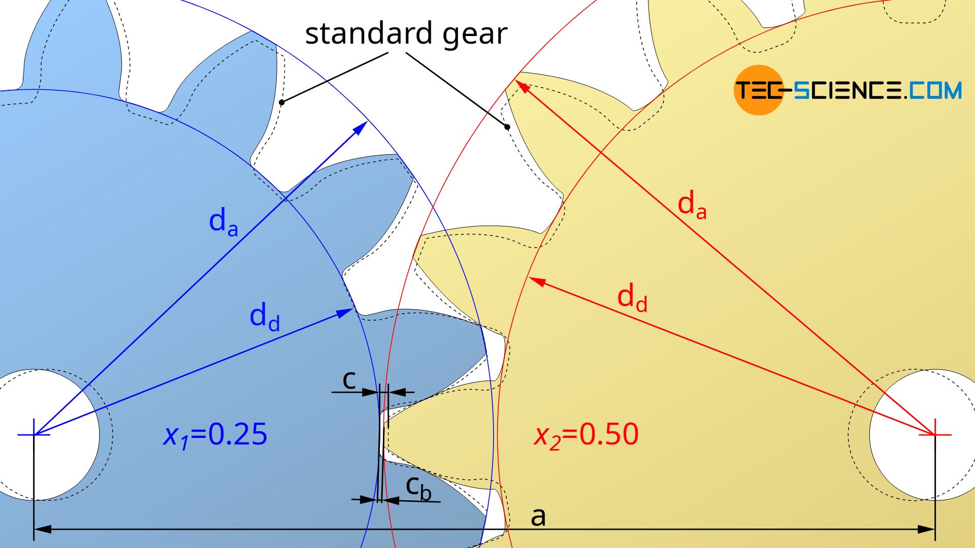
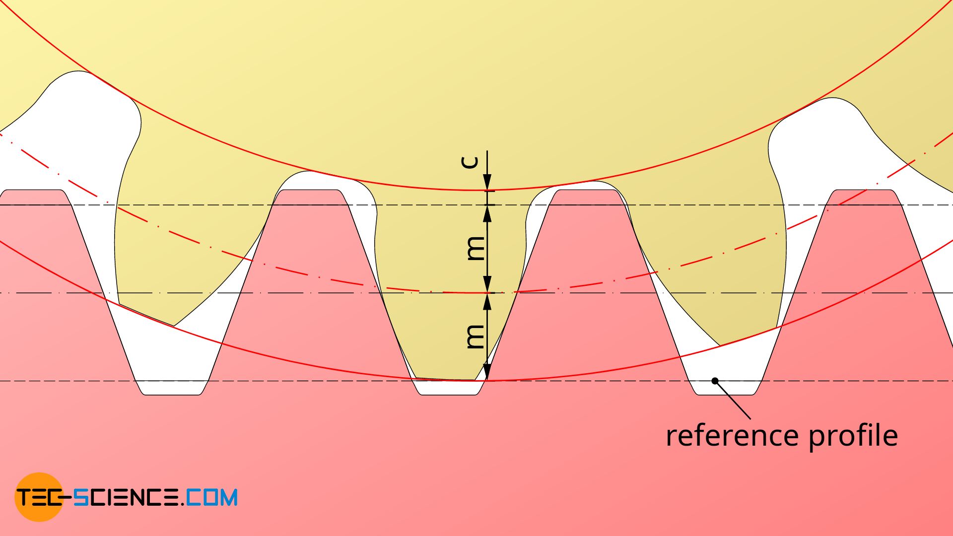
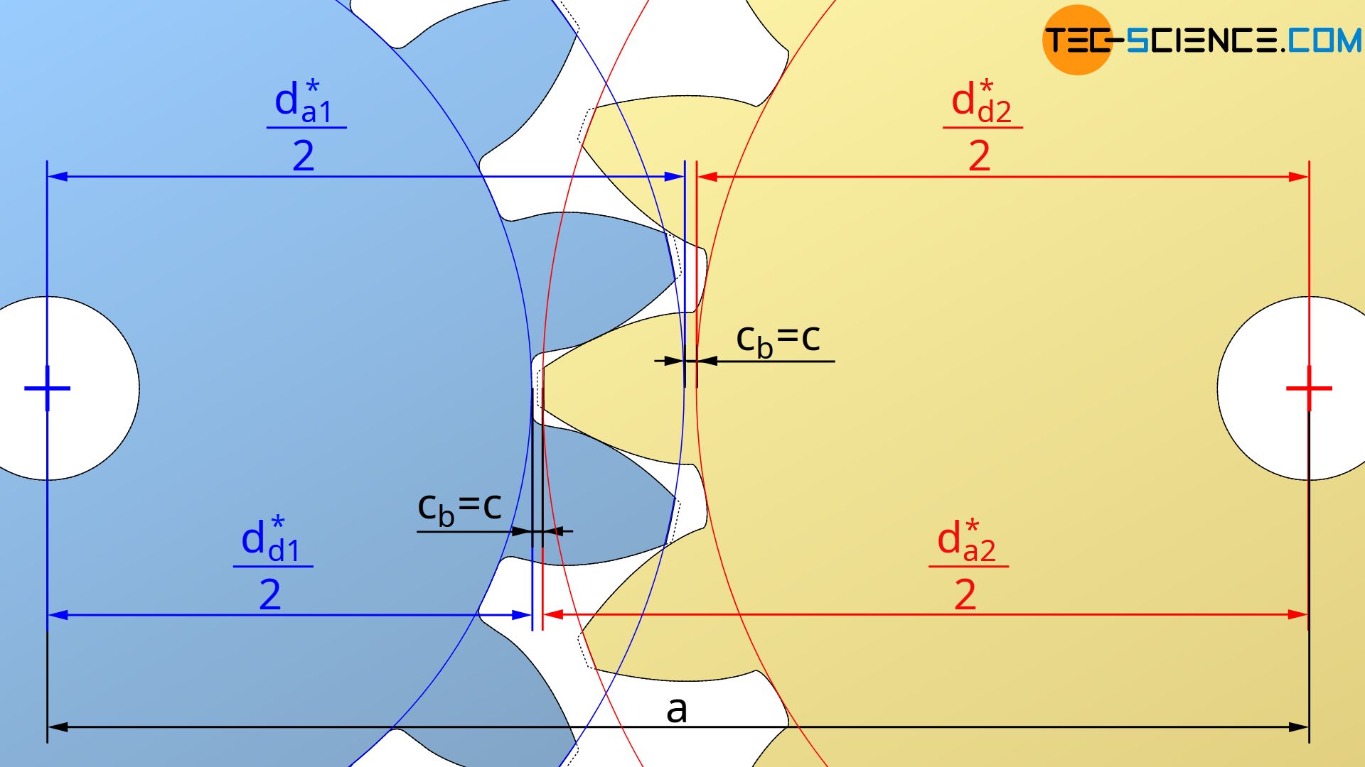
The manufacturing tip tooth clearance c given in equation (\ref{f}) therefore refers only to the clearance between tool and gear during gear cutting (see figure below). The operating tip tooth clearance cb, on the other hand, refers to the actual clearance in operation between the tip of the tooth of one gear and the root of the tooth of the mating gear. Only in the case of non-corrected standard gears are both manufacturing clearance and operating clearance identical.
The reduction of the operating tip tooth clearance when corrected gears are engaging therefore makes it necessary to shorten the tip circles if the required tip tooth clearance c is to be maintained during operation. The amounts da* to which the tip circles must be shortened are shown in the following sections.
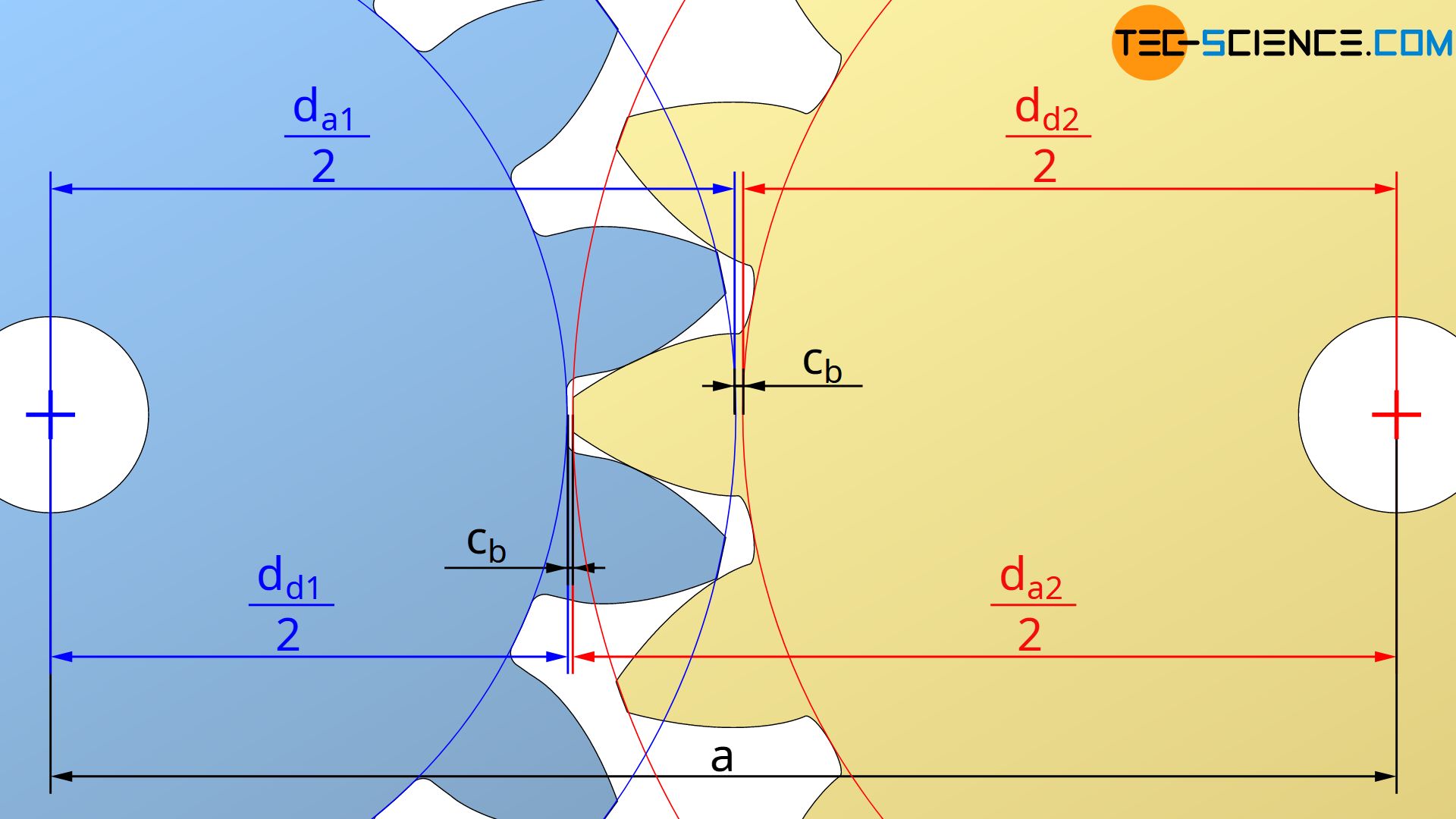
The figure below shows that the operating tip tooth clearance cb is generally determined by the center distance “a”, the root diameter dd1 of one gear and the tip diameter da2 of the mating gear:
\begin{align}
\label{cb}
&c_b = a – \frac{d_{d1}}{2} – \frac{d_{a2}}{2} \\[5px]
\end{align}
If equation (\ref{f}) is applied in equation (\ref{cb}), then the operating tip tooth clearance cb can be determined from the manufacturing tip tooth clearance c as follows:
\begin{align}
&c_b = a – \frac{\overbrace{ m \cdot (z_1+2x_1-2) -2c }^{d_{d1}}}{2} – \frac{d_{a2}}{2} \\[5px]
\label{cc}
&\boxed{c_b = a – m \cdot \left( \frac{z_1}{2} + x_1 – 1 \right) – \frac{d_{a2}}{2} + c } \\[5px]
\end{align}
If the tip diameter is to be adjusted so that the operating tip tooth clearance cb equals the manufacturing tip tooth clearance c=cb, then equation (\ref{cc}) can be solved for the shortened tip diameter da2*:
\begin{align}
&c_b = a – m \cdot \left( \frac{z_1}{2} + x_1 – 1 \right) – \frac{d_{a2}^\text{*}}{2} + c \overset{!}{=} c \\[5px]
&a – m \cdot \left( \frac{z_1}{2} + x_1 – 1 \right) – \frac{d_{a2^\text{*}}}{2} = 0 \\[5px]
\label{da2}
&\boxed{d_{a2}^\text{*} = 2 a – m \cdot \left(z_1 + 2 x_1 – 2 \right) } \\[5px]
\end{align}
The analog equation applies to the tip diameter da1*:
\begin{align}
\label{da1}
&\boxed{d_{a1}^\text{*} = 2 a – m \cdot \left(z_2 +2 x_2 – 2 \right) } \\[5px]
\end{align}
Note that the tip shortenings according to the equations (\ref{da2}) and (\ref{da1}) are not dependent on the tip tooth clearance itself!
Calculation of the contact ratio
In the article Meshing of in volute gears it has already been explained that the line of action results as a tangent to the base circles of the meshing gears. The actual line of contact runs from the intersection point A between the line of action and the tip circle of the driven gear to the intersection point E between the line of action and the tip circle of the driving gear. The ratio of the line of contact l to the base pitch pb (distance between two adjacent contact points) is called contact ratio ε.
\begin{align}
&\boxed{\epsilon = \frac{l}{p_b}} >1 \\[5px]
\end{align}
For continuous power transmission, a new tooth must be engaged before the preceding tooth leaves the line of contact. The contact ratio must therefore always be greater than one. The determination of this contact ratio of two profile shifted gears will be shown in the following sections.
Since the base pitch pb is already be determined by equation (\ref{pb}), only the line of contact l has to be calculated. For the derivation of the formula to calculate the line of contact l, the figure below is used. The figure shows that the sum of the distances T1E (yellow triangle) and T2A (blue triangle) is greater by the amount of the line of contact l than the distance T1T2. For the line of contact l therefore applies:
\begin{align}
& \overline{T_1 E} + \overline{T_2 A} – l = \overline{T_1 T_2} \\[5px]
\label{0}
& \underline{ l = \overline{T_1 E} + \overline{T_2 A} – \overline{T_1 T_2} } \\[5px]
\end{align}
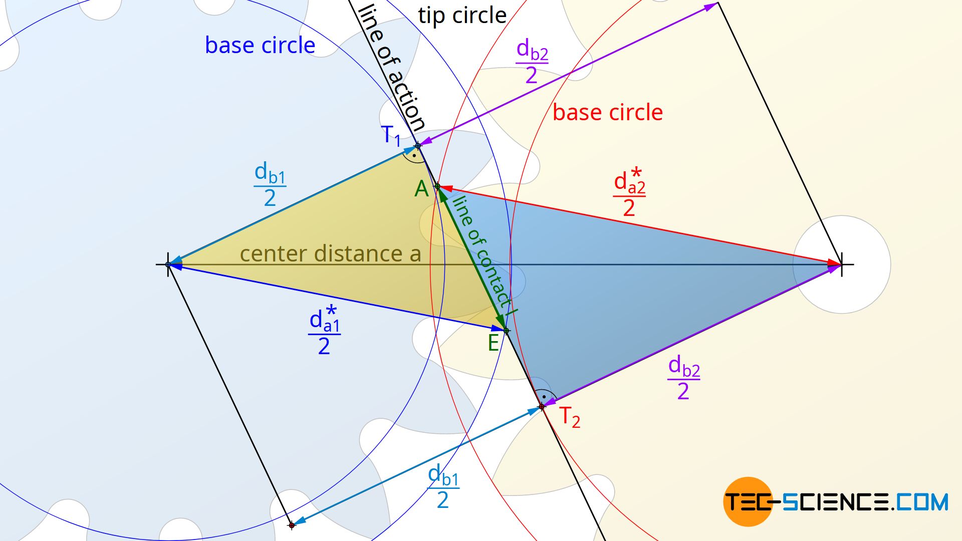
The distance T1E can be determined from the yellow triangle using the base circle diameter db1 and the (possibly shortened) tip diameter da1*:
\begin{align}
& \left( \frac{d_{a1}^\text{*}}{2} \right)^2 = \overline{T_1 E}^2 + \left( \frac{d_{b1}}{2} \right)^2 \\[5px]
\label{11}
&\underline{ \overline{T_1 E} = \sqrt{ \left( \frac{d_{a1}^\text{*}}{2} \right)^2 – \left( \frac{d_{b1}}{2} \right)^2} }\\[5px]
\end{align}
The distance T2A can be determined by the blue triangle using the base circle diameter db2 and the (possibly shortened) tip diameter da2*:
\begin{align}
& \left( \frac{d_{a2}^\text{*}}{2} \right)^2 = \overline{T_2 A}^2 + \left( \frac{d_{b2}}{2} \right)^2 \\[5px]
\label{2}
&\underline{ \overline{T_2 A} = \sqrt{ \left( \frac{d_{a2}^\text{*}}{2} \right)^2 – \left( \frac{d_{b2}}{2} \right)^2} }\\[5px]
\end{align}
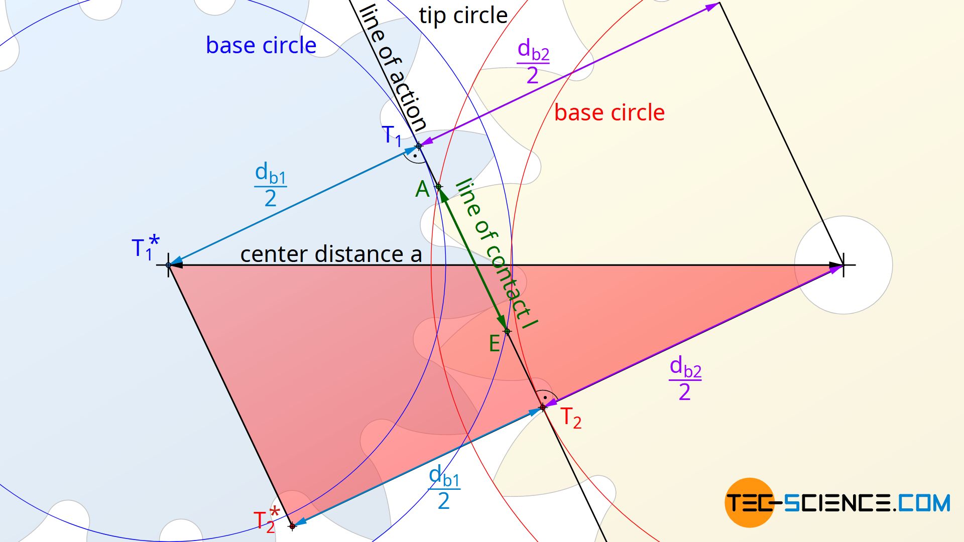
The distance T1T2=T1* T2* results from the red marked triangle in the figure below on the basis of the center distance “a” as well as the base circle diameter db1 resp. db2:
\begin{align}
& a^2 =\overline{T_1 T_2}^2 + \left( \frac{d_{b1}}{2} + \frac{d_{b2}}{2} \right)^2 \\[5px]
\label{3}
& \underline{\overline{T_1 T_2} = \sqrt{a^2 – \left( \frac{d_{b1}}{2} + \frac{d_{b2}}{2} \right)^2} } \\[5px]
\end{align}
The equations (\ref{11}), (\ref{2}) and (\ref{3}) can now be applied to equation (\ref{0}):
\begin{align}
& l = \overline{T_1 E} + \overline{T_2 A} – \overline{T_1 T_2} \\[5px]
& l = \sqrt{ \left( \frac{d_{a1}^\text{*}}{2} \right)^2 – \left( \frac{d_{b1}}{2} \right)^2} + \sqrt{ \left( \frac{d_{a2}^\text{*}}{2} \right)^2 – \left( \frac{d_{b2}}{2} \right)^2} – \sqrt{a^2 – \left( \frac{d_{b1}}{2} + \frac{d_{b2}}{2} \right)^2} \\[5px]
\label{l}
& \boxed{l = \frac{1}{2} \left[ \sqrt{ d_{a1}^\text{* 2} – d_{b1}^2} + \sqrt{ d_{a2}^\text{* 2} – d_{b2}^2 } – \sqrt{ 4 a^2 – \left( d_{b1} + d_{b2} \right)^2} \right]} \\[5px]
\end{align}
The base circle diameters db in equation (\ref{l}) can be determined by the module m, the standard pressure angle α0 and the respective number of teeth z:
\begin{align}
&d_b = \overbrace{d_0}^{= m \cdot z} \cdot \cos(\alpha_0) \\[5px]
&\boxed{d_b = m \cdot z \cdot \cos(\alpha_0) } \\[5px]
\end{align}
Finally, all parameters for determing the contact ratio ε can be calculated:
\begin{align}
&\boxed{\epsilon = \frac{l}{p_b}} \\[5px]
\text{with} \\[5px]
&\boxed{p_b= \pi \cdot m \cdot \cos(\alpha_0)} \\[5px]
\text{and} \\[5px]
&\boxed{l = \frac{1}{2} \left[ \sqrt{ d_{a1}^\text{* 2} – d_{b1}^2} + \sqrt{ d_{a2}^\text{* 2} – d_{b2}^2 } – \sqrt{ 4 a^2 – \left( d_{b1} + d_{b2} \right)^2} \right]} \\[5px]
&\boxed{d_{b1} = m \cdot z_1 \cdot \cos(\alpha_0) } \\[5px]
&\boxed{d_{b2} = m \cdot z_2 \cdot \cos(\alpha_0) } \\[5px]
\end{align}
The tip diameters da* correspond to the shortened tip circles, if a tip shortening was carried out.
The formulas given for the calculation of the contact ratio only apply to gears without undercut! In the case of undercutted gears, the line of contact is shortened and the contact ratio is thus reduced!
Excel spreadsheet for calculating involute gears
The following Excel spreadsheet for gear calculation offers the possibility to calculate different geometric parameters of involute gears:
- center distance
- tip shortening
- sum of the profile shift coefficients to obtain a certain center distance
- operating pressure angle
- transmission ratio
- standard reference pitch circle
- operating pitch circle
- tip, root and base circle diameter
- tip tooth clearance
- (tip) tooth thickness
- contact ratio
The calculations have not yet been completely checked for correctness!


")
")

