Involute toothing is often used in mechanical engineering for gears, as it offers favorable meshing and is easy to produce.
Introduction
In mechanical engineering, the involute is used almost exclusively as a tooth form for gears. Such gears are called involute gears. The use of involute toothing is due on the one hand to the favorable meshing (engagement of two gearwheels). On the other hand, involute gears can be manufactured cost-effectively due to the relatively simple tool geometry.

Construction of an involute
In the case of involute toothing, the shape of the tooth flanks consists of two involutes of circles (called involutes for short). An involute is constructed by rolling a so-called rolling line around a base circle. The resulting trajectory curve describes the shape of the involute. Two mirror-inverted involutes then form the basic shape of a tooth.

The involute can also be constructed by unwinding a string from a circle. The string is always kept taut during unwinding. The end of the string then also describes the shape of the involute.

An involute is constructed by unwinding a rolling line on a base circle or by unwinding a string from the base circle!
The longer the involute, the greater the curvature radius, i.e. the smaller the curvature of the involute. From the construction of the involute it becomes clear that the radius of curvature corresponds exactly to the arc length on the base circle.

The longer the involute, the less curvature it has!
However, the flank shape cannot only be influenced by changing the base circle diameter. By means of a so-called profile shift, the tooth flanks of gearwheels are composed of the more distant part of the involute, while the base circle diameter remains the same. The tooth flank is therefore less curved and “flatter”. During meshing with another gear, the contact forces can thus be distributed more evenly. This reduces the tooth load and thus the tooth wear.
Profile shifted gears use the less curved part of the involute for the tooth shape!
Nomenclature
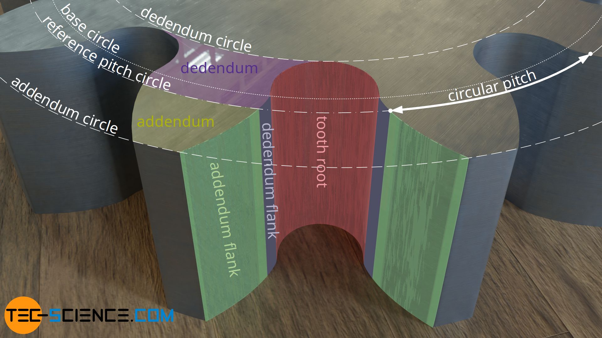
In order to avoid contact between the tip and the root of the tooth of two meshing gears, the root of the tooth is rounded out (called fillet). The resulting diameter at the root of the tooth is called the root diameter (dedendum circle). Analogous to the root diameter, a tip diameter can be assigned to the tip of the gear (addendum circle).
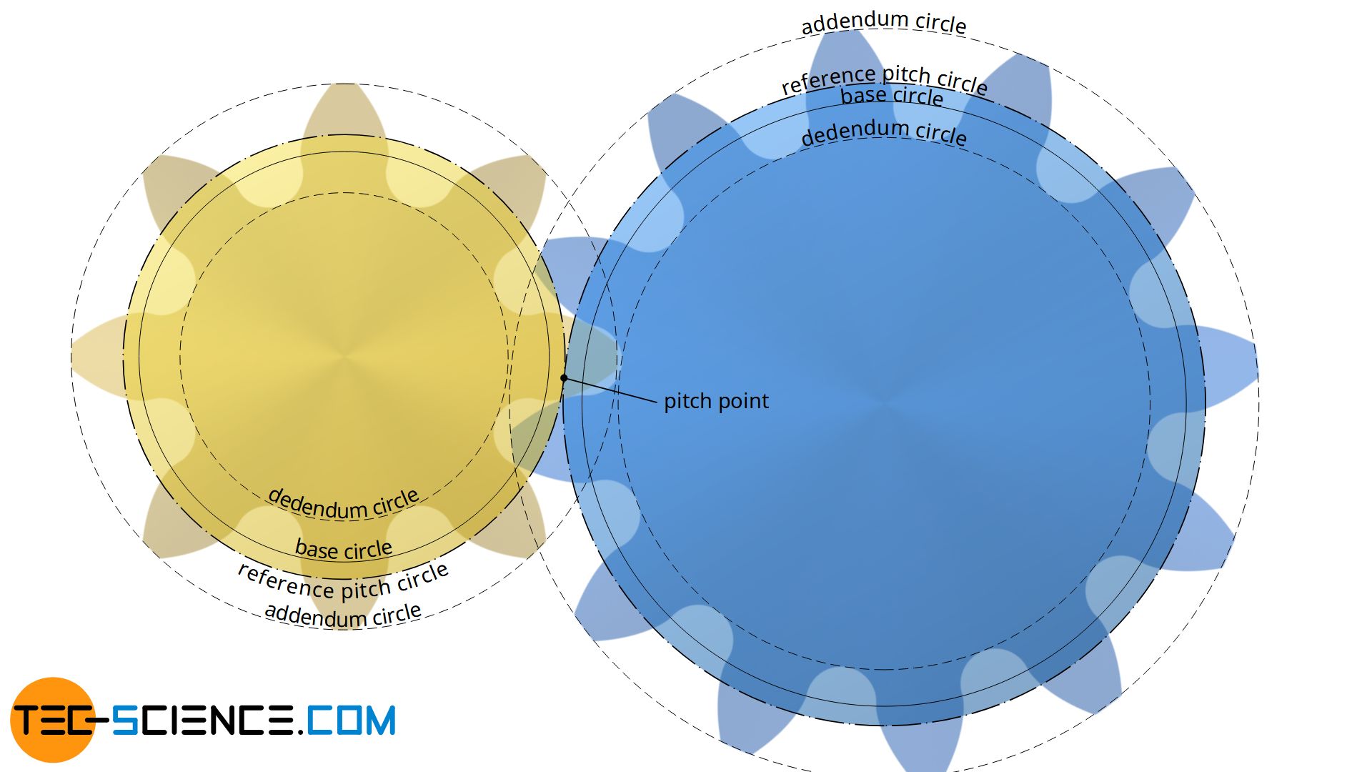
Note, that there is no contact between the tooth flanks of two meshing gears within the base circle! For further information see article meshing.
There is no contact of the tooth flanks within the base circle!
The size of a gearwheel is defined by the so-called standard reference pitch diameter. Strongly simplified, this diameter corresponds to the diameters of imaginary cylinders that roll on each other. The tooth spacing is related to this diameter and is referred to as the circumferential pitch or circular pitch. The circular pitch is the arc distance between two tooth flanks of the same direction on the pitch circle. This circular pitch must be identical for all gears so that the teeth can mesh without interfering.
The spacing of the teeth can basically also be related to the base circle. In this case, the pitch is then referred to as the base pitch. More detailed information on this can be found in the next section.
Tooth size: the module
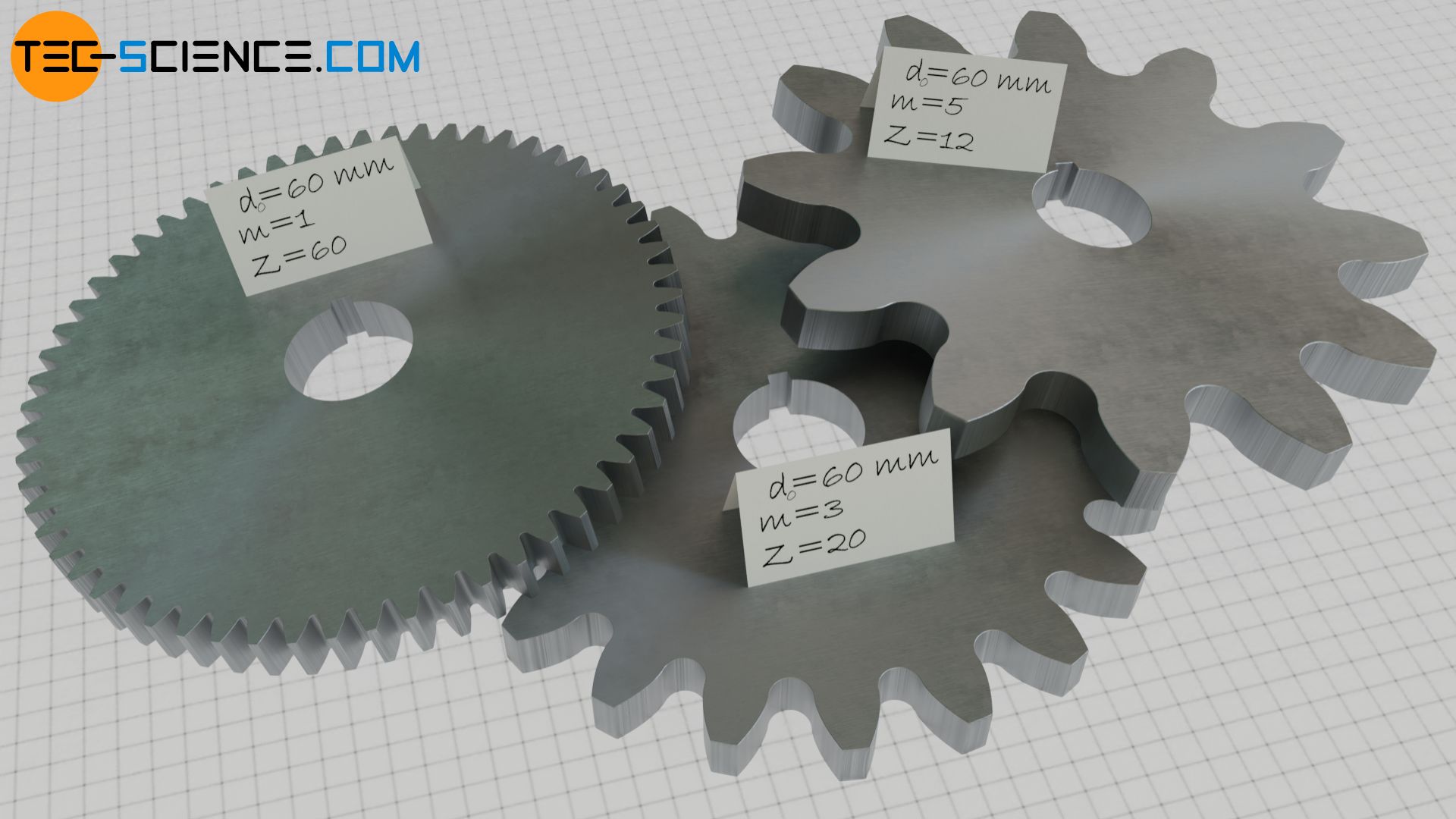
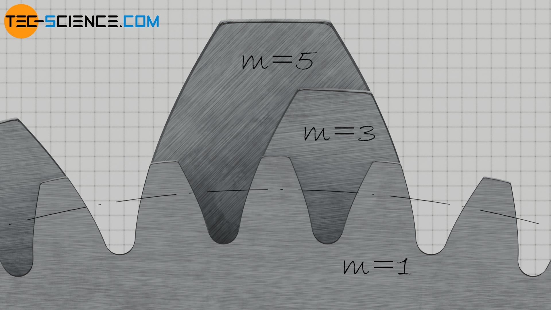
In order to characterize gears and above all to ensure that the teeth of two gears can mesh properly, one of the most important parameters is the so-called module m. The module is a measure of the tooth size of a gear and is usually given in millimeters (if the unit is in inches, the module is also called “English Module”.). Only if the teeth of gears are of the same size and thus have the same module can they be paired with each other!
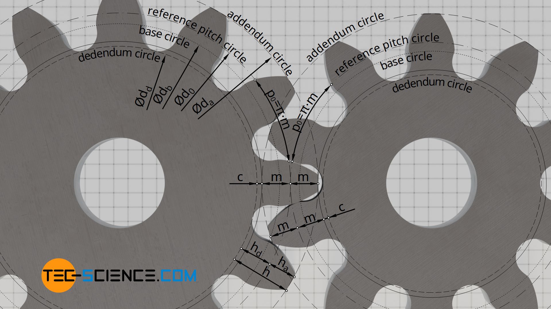
The module corresponds directly to the addendum ha. The dedendum hd also results from the module, whereby a clearance c is also taken into account. The clearance corresponds to the amount by which the tooth root is additionally deepened to avoid contact between the tip and root of two gearwheels. Depending on the application, the clearance is typically 10% to 30% of the module (often 0.167⋅m). The whole depth of the tooth h thus results from twice the value of the module m, plus the clearance c.
\begin{align}
&\boxed{h_a = m} ~~~\text{addendum} \\[5px]
&\boxed{h_d = m + c} ~~~\text{dedendum} \\[5px]
&\boxed{c = 0,167 \cdot m} ~~~\text{clearance } \\[5px]
&\boxed{h = h_a + h_d = 2 \cdot m + c} ~~~\text{whole depth} \\[5px]
\end{align}
The module is a measure of the tooth size: the larger the module, the larger the tooth! Only gears with the same module can be paired!
The figure below shows three gears of the same size (i.e. identical reference pitch circles), but manufactured with different modules. The next section deals with the reference pitch circle in more detail.
Gear size: the standard reference pitch diameter
If the clearance is neglected for now, the tooth is “divided” by the standard reference pitch diameter at half depth, so to speak. The standard reference pitch diameter d0 results from the product of module m and number of teeth z and is a measure for the size of the gear:
\begin{align}
&\boxed{d_0 = m \cdot z} ~~~\text{standard reference pitch diameter} \\[5px]
\end{align}
Note that, in contrast to the so-called operating pitch diameter, the reference pitch diameter is a fixed size of a gearwheel which is determined solely by the product of the module and the number of teeth.
The standard reference pitch diameter serves only as a reference circle for specifying the circular pitch p0, i.e. the tooth spacing which must be identical for all gears if they are to mesh. This arc length p0 between two identical tooth flanks can be determined from the quotient of the pitch circle circumference u0=π⋅d0 and the number of teeth z:
\begin{align}
&p_0 = \frac{u_0}{z} = \frac{\pi \cdot d_0}{z} = \frac{\pi \cdot m \cdot z}{z} = m \cdot \pi \\[5px]
&\boxed{p_0 = m \cdot \pi} ~~~\text{circular pitch} \\[5px]
\end{align}
At this point it becomes again clear that only gears with identical modules can be paired with each other, because obviously only then the tooth spacing p0 for all gears are identical and the teeth can mesh properly.
The standard reference pitch diameter is a measure for the size of a gearwheel. The circular pitch of the teeth is related to this diameter. All gears to be paired must have identical circular pitches on their standard reference pitch circles and thus identical modules!
The standard reference pitch diameter d0 can now be used to determine the tip diameter da (addendum circle) and the root diameter dd (dedendum circle):
\begin{align}
&d_a =d_0 + 2 \cdot h_a = m \cdot z + 2 \cdot m \\[5px]
&\boxed{d_a =m \cdot (z+2)} ~~~\text{tip diameter (addendum circle diameter)} \\[5px]
&d_d = d_0 – 2 \cdot h_d = m \cdot z – 2 \cdot (m+c) \\[5px]
&\boxed{d_d = m \cdot (z-2) – 2 \cdot c} ~~~\text{root diameter (dedendum circle diameter)} \\[5px]
\end{align}
For gears that are not profile-shifted, the circular tooth thickness s0 and the tooth space width e0 on the reference pitch circle are identical in length and thus correspond to half the circular pitch p0. Two gears can thus be paired without backlash. Thus no “rattling” occurs during the change of the direction of rotation.
\begin{align}
&\boxed{s_0 = e_0 = \frac{p_0}{2} = \frac{m}{2} \cdot \pi} ~~~\text{circular tooth thickness , tooth space width} \\[5px]
\end{align}
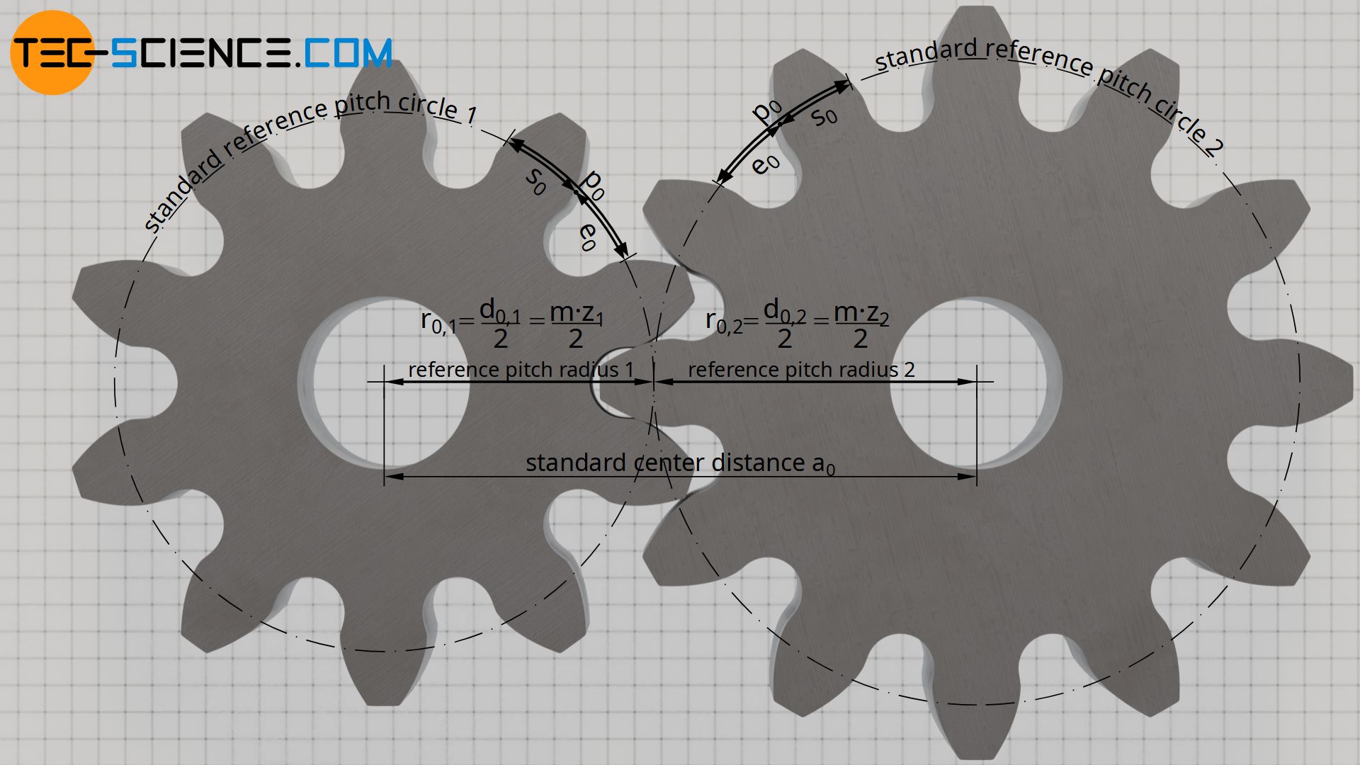
The center distance of the two non-profile shifted gears for backlash-free pairing is referred to as the standard center distance a0. The standard center distance results from the sum of the two reference pitch radii or half the sum of the reference pitch diameters:
\begin{align}
&\boxed{a_0 = \frac{d_{0,1}+ d_{0,2} }{2} = \frac{m}{2} \cdot (z_1+z_2)} ~~~\text{standard center distance} \\[5px]
\end{align}
Diametral pitch
Instead of the module, the so-called diametral pitch is often used as a measure of the tooth size. The diametral pitch DP corresponds to the inverse of the module m:
\begin{align}
&\boxed{DP = \frac{1}{m} = \frac{z}{d_0} } ~~~\text{diametral pitch} \\[5px]
\end{align}
Therefore, the diametral pitch indicates how many teeth per unit length of pitch diameter a gearwheel has.
Author’s note: The term diametral pitch ist somewhat a little bit confusing, since in contrast to the terms base pitch oder circular pitch, the diametral pitch doesn’t state a “distance per tooth”, but just the opposite: “tooth per distance”. To be consistent, the module m should therefore be the “real diametral pitch”. This inconsistence is the reason why I’m not using the term diametral pitch any further, but only the module.
Tooth shape: the pressure angle
If the teeth of gears are to mesh perfectly, not only the tooth sizes must match (described by the module m), but also the tooth flank shape must match. This flank shape is described by the so-called pressure angle. The pressure angle is described in more detail in this section.
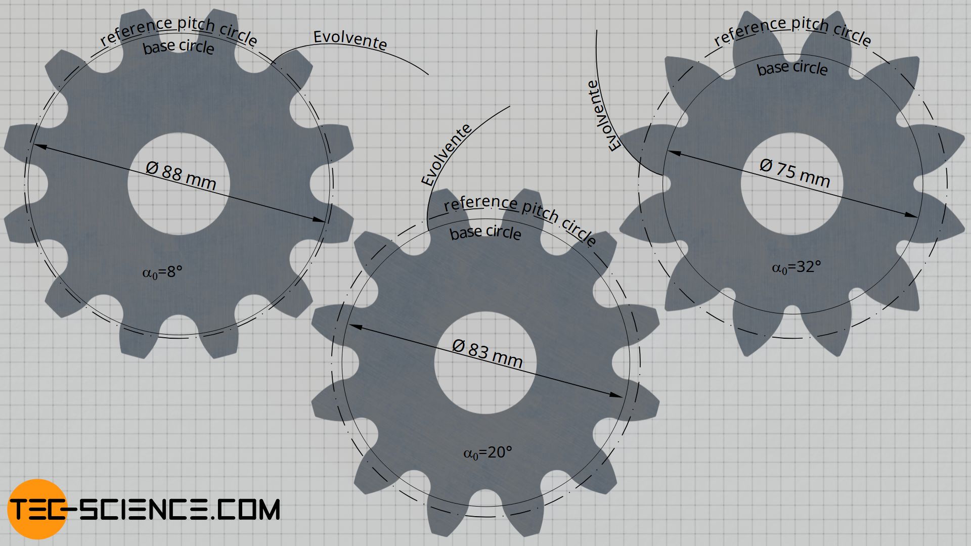
The shape of the involute and thus the tooth flank is only dependent on the base circle diameter. Each base circle therefore always has a specific involute. All involutes are geometrically similar, i.e. they can be “scaled” (enlarged or reduced in size) to the same shape.
The flank shape of a gear is determined by the base circle diameter, whereby all involutes of any base circles are geometrically similar to each other!
If larger base circle diameters are used to construct the tooth flanks for a certain gear size (i.e. for identical pitch diameters), the teeth will tend to look “square”. With smaller base diameters, however, the tip of the teeth tend to look “pointed”. The figure below shows the tooth shapes for different base diameters with identical reference pitch circles. The tooth size, i.e. the module, was chosen the same for all gears!
Two gears can only mesh properly if they have the same tooth shape. This is only the case if the ratio of base circle diameter to reference pitch diameter is identical for all gears. When increasing the number of teeth and thus the reference pitch diameter, the base circle diameter must increase by the same amount so that the tooth shape remains identical (this corresponds to the “scaling” of the involutes mentioned above).
In addition to the module, a further parameter must therefore be defined which describes the ratio of the base circle diameter to the reference pitch diameter and thus the tooth shape. The relationship between the base circle and the pitch circle becomes apparent when two gears with no profile shift are paired without backlash. In this case, the center distance corresponds to the standard center distance a0 and the pitch circles of both gears touch each other at the so-called pitch point C.
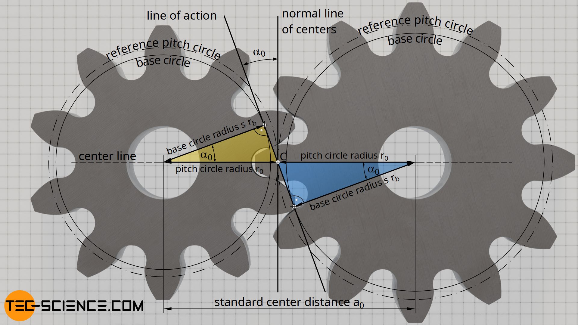
If a tangent is now applied to the two base circles of the gears, this so-called line of action encloses a certain angle with the normal of the center line. This angle is called the pressure angle α0. As the yellow and blue triangles in the figure above show, the base circle radii rb and the pitch circle radii r0 are related by this pressure angle α0:
\begin{align}
&\cos(\alpha_0) = \frac{r_b}{r_0} \\[5px]
&\boxed{\cos(\alpha_0) = \frac{d_b}{d_0}} ~~~\alpha_0 \text{ : pressure angle} \\[5px]
\end{align}
In practice, the diameter ratio of the base circle to the pitch circle, and thus the flank shape, is determined by this pressure angle. Independent of the module, a pressure angle of α0 = 20° is usually used for all gears. However, there are also gears with pressure angles of 14.5° or 25°.
In the figure “Flank shape for different base circle diameters”, a pressure angle of 8° was selected for the left gear and an angle of 20° for the center gear and an angle of 32° for the right gear.
The fact that the pressure angle directly determines the flank shape of a gear is also immediately obvious from an manufacturing point of view. In general, gears are manufactured by gear hobbing. In this case, the flank shape of the gear is determined by the inclination of the cutting edges of the rack-shaped tool profile. This tool angle corresponds directly to the pressure angle α0!
Note:
– the module is a measure for the tooth size!
– The standard reference pitch diameter is a measure for the gear size!
– The pressure angle is a measure for the shape of the tooth flank!
Base pitch
All involutes of a gear are equidistant to each other, i.e. the right-angled distances of two adjacent involutes are identical for all points on an involute. This right-angled distance also corresponds to the arc section on the base circle, since the involutes are constructed by rolling a rolling line on the base circle without sliding. This curved distance of the involutes on the base circle (= curved distance of the tooth flanks!) is therefore also called base pitch pb.

The base pitch pb on the base circle is not to be confused with the circular pitch p0 on the pitch circle. However, both pitches are not independent of each other. Just as the base circle diameter and the reference pitch diameter are proportional to each other by the pressure angle α0 (see previous section), the same ratio also applies to the corresponding pitches on the base circle and the pitch circle:
\begin{align}
&\boxed{\cos(\alpha_0) = \frac{p_b}{p_0}} \\[5px]
\end{align}
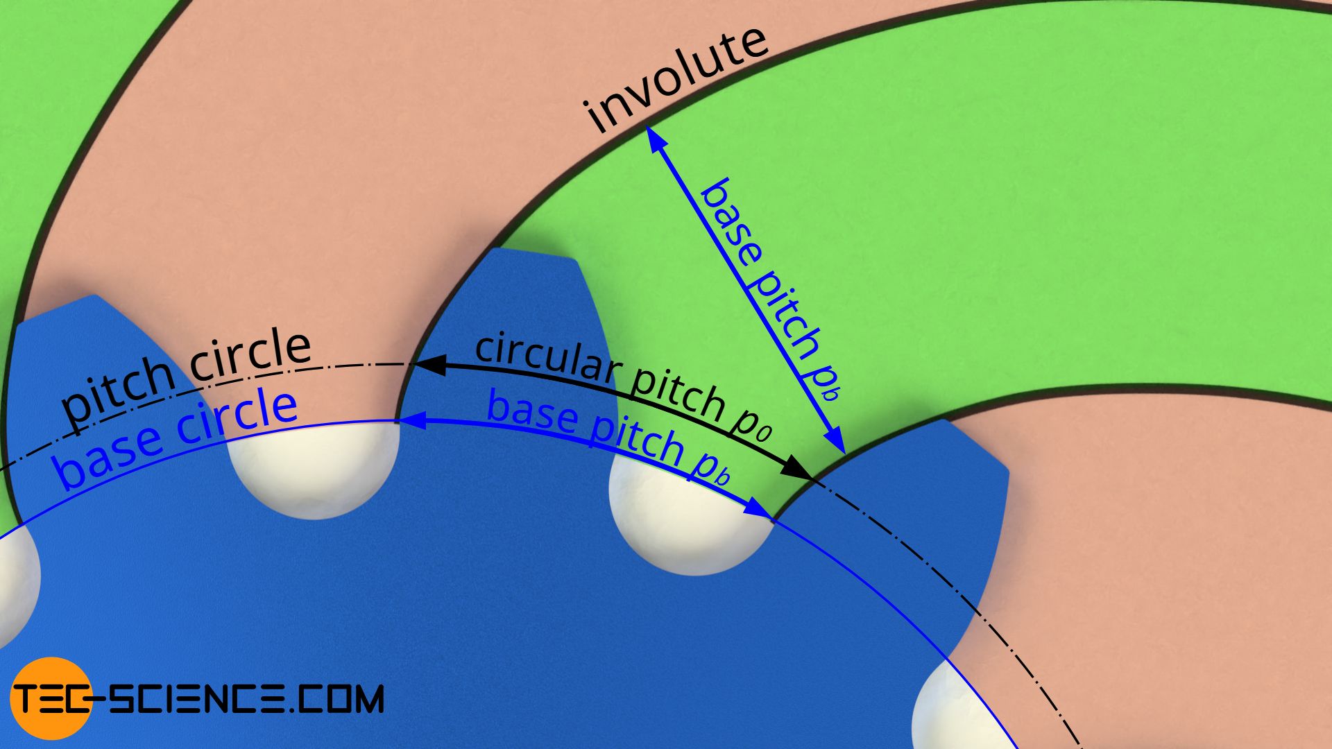
The rectangular distance between two involutes (i.e. the base pitch!) also corresponds to the distance between two tooth flanks touching each other during meshing (“meshing pitch”)!
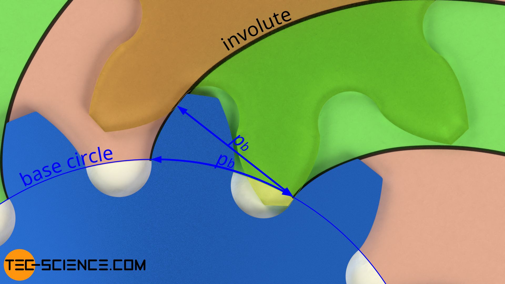
The base pitch corresponds to the distance between two meshing flanks and results from the right-angled distance between two adjacent involutes (“meshing pitch”)!
More information on the engagement of two involute gears can be found in the article Meshing of involute gears.


")

")
