In this article, learn more about the meshing of the teeth of a gear with the teeth of a rack.
Introduction
The fundamentals when two gears are meshing have already been explained in detail in the article Engaging of involute gears (meshing). In this article a special “gear” will be examined: the rack. The animation below shows the engagement of a driving gear with a driven rack.
Line of contact
A rack is basically a special case of a gear with an infinitely large diameter. The curved flanks finally change into straight flanks. The flanks are just inclined by the amount of the standard pressure angle α0 against the vertical. The line of action is also inclined by this angle α0 (= operating pressure angle), since the line of action is perpendicular to the rack flanks. As usual, the line of action is a tangent to the base circle of the gear and is thus clearly defined.
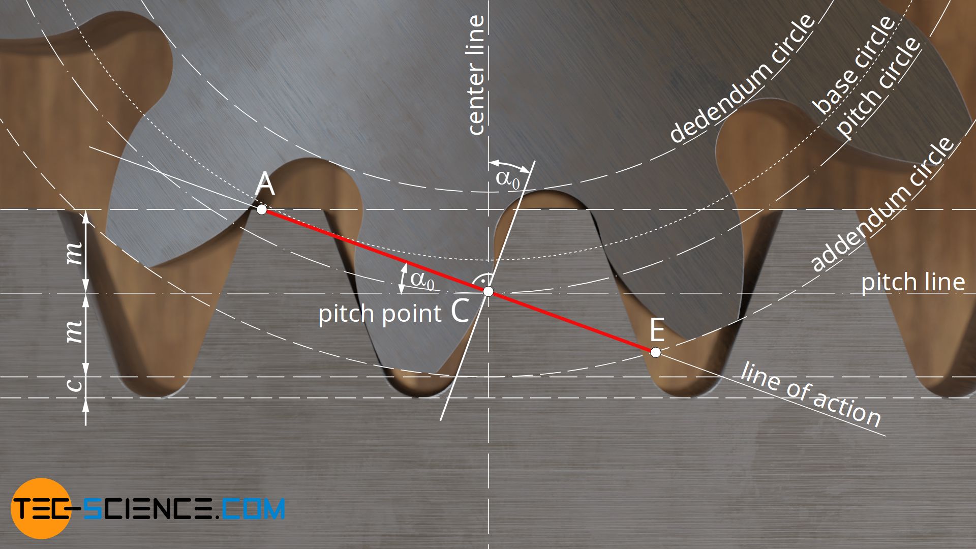
The line of contact begins analogous to the pairing of two gears at the intersection A between the line of action and the addendum circle of the driven gear, which in the case of a rack ist an addendum line. Likewise, the end of the line of contact E is again defined by the intersection between the line of action and the addendum circle of the driving gear.
Pitch point
Analogous to two gears, the pitch point C is located at the intersection between the line of action and the center line. Since such a center line always points in the radial direction of a gear and is thus always perpendicular to the “surface” of the gear, in the case of a rack it is thus perpendicular to the racks “surface”. Thus the pitch point C is also cleary defined.
With backlash-free meshing, the rack sits firmly with both flanks on the tooth flanks of the gear. Shifting the rack in radial direction does not change the position of the line of action, which is always the flank normal of the rack and the tangent of the gear’s base circle. Neither the base circle nor the flank angle change in this case, so that the line of action remains identical. This also does not result in any changes in the position of the pitch point, since the center line is also retained! The only effect of a distance change is on the length of the line of contact, which is shortened by a radial displacement of the rack away from the gear.
The position of the pitch point always remains constant with racks! The line of contact is shortened if the distance between rack and gear is increased!
The unchangeable position of the pitch point is also immediately apparent from its definition. The pitch point is defined as the point at which the circumferential speeds of both “gears” are identical. In the case of the rack, however, it is a translatory motion. Each point on the rack thus always moves at the same speed, regardless of the distance to the gear. This also does not change the pitch circle on the gear whose points move at the same speed as the rack. The pitch circle remains identical and so does the pitch point!
Definition of the standard reference pitch circle
As explained in the section before, the pitch point is independent of the distance between gear and rack! The pitch line of the rack and the pitch circle of the gear (both of which run through the pitch point) do not change either! This fact plays a special role especially when manufacturing gears with the help of rack-shaped tools (hob cutters). This means that even in the case of so-called profile shifts (which are equivalent to the radial displacement of the rack), identical pitch circles always occur on a gear. These are then also referred to as manufacturing pitch circles.
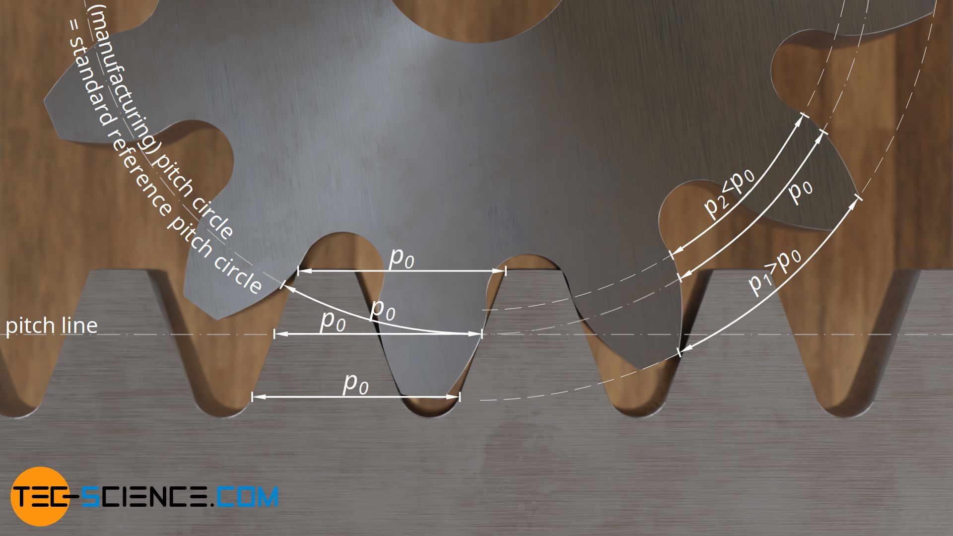
In contrast to a gear, rack-shaped tools (or racks) have identical tooth spacings p0 at every point. In the case of gear, however, these tooth spacings depend on the circumference of the circle under consideration. With increasing diameter, which is considered, the teeth are also distributed on an ever larger circumference and the tooth distance consequently increases. Only where the teeth of the rack-shaped tool (or rack) “roll” directly on the gear are identical tooth spacings found (circumferential pitches or circular pitches p0). By definition, this corresponds to the manufacturing pitch circles.
For this reason, the manufacturing pitch circles are also called standard reference pitch circles, since the circumferential pitches p0 are identical for all gears manufactured with the same rack-shaped tool. The standard reference pitch circle is therefore a fixed (unchangeable) parameter of a gear, which is determined solely by the rack-shaped cutting tool! Therefore, a rack can actually be used as a definition of the standard reference pitch circle of a gear:
The standard reference pitch circle of a gear corresponds to the manufacturing pitch circle when manufacturing the gear with a rack-shaped tool! Or in case of an actual rack: The standard reference pitch circle of a gear corresponds to the operating pitch circle when meshing with a rack!
The always identical circular pitches on the manufacturing pitch circles make it possible not only to pair “normal” gears with profile-shifted gears, but also to combine gears of any size, i.e. any number of teeth, if these were manufactured with the same rack-shaped tool!

")

")

