The conversion of speed and torque takes place in gearboxes through the arrangement of gears or pulleys of different sizes.
Conversion of speed
As explained in the article What is a transmission (gearbox) and what is it used for?, transmissions are used, among other things, to set the speed to a desired value. Such a conversion of the speed becomes obvious when looking at the animated gear transmission below. In this case, the speed is reduced from gear to gear.
The reduction in speed can be attributed to the different number of teeth between the respective pairs of gears. For example, the first driving gear (green) on the drive shaft has a total of 15 teeth. As a result, these 15 teeth rotate completely once when the gear wheel is turned. They push the following driven gear (orange) by 15 teeth further.
However, this driven gear has more teeth due to its larger diameter. As a result, it no longer moves by a full turn. In the present case, the driven gearwheel has a total of 30 teeth. Thus, during one rotation of the driving gearwheel, the driven gearwheel is pushed on by only half a rotation. This ultimately means a halving of the speed.
Note that the individual teeth of the larger gears also have the same dimensions as the teeth of the smaller gears, as the respective teeth must fit togehter. Such an interlocking of gears is also called meshing.
Transmission ratio
The change in speed from a driving to a driven wheel is described by the so-called transmission ratio i. It is defined as follows:
\begin{align}
\label{def_uebersetzungsverhaeltnis}
&\boxed{i = \frac{n_1}{n_2}} \\[5px]
\end{align}
In this equation, n1 denotes the rotational speed of the driving wheel and n2 the rotational speed of the driven wheel. If the direction of rotation is reversed with a gearstage, this is usually indicated by a negative sign. For reasons of simplicity, however, this convention will not be applied in the following.
In the case described above, the transmission ratio between the two gears is i = 2, which means that the driving wheel rotates twice as fast as the driven wheel or the driven wheel moves only half as fast as the driving wheel. Frequently, transmission ratios are also given in the form 2:1 (“two to one”).
The transmission ratio is defined as the ratio of the rotational speeds of the driving wheel to the driven wheel. It descriptively shows how often the driving wheel has to turn for one rotation of the driven wheel!
Gear drive
For two paired gears, the transmission ratio is determined by the (inverse) ratio of the number of teeth z or the corresponding pitch circle diameter d:
\begin{align}
\label{zaehne_uebersetzungsverhaeltnis}
&\boxed{i = \frac{z_2}{z_1} = \frac{d_2}{d_1}} \\[5px]
\end{align}
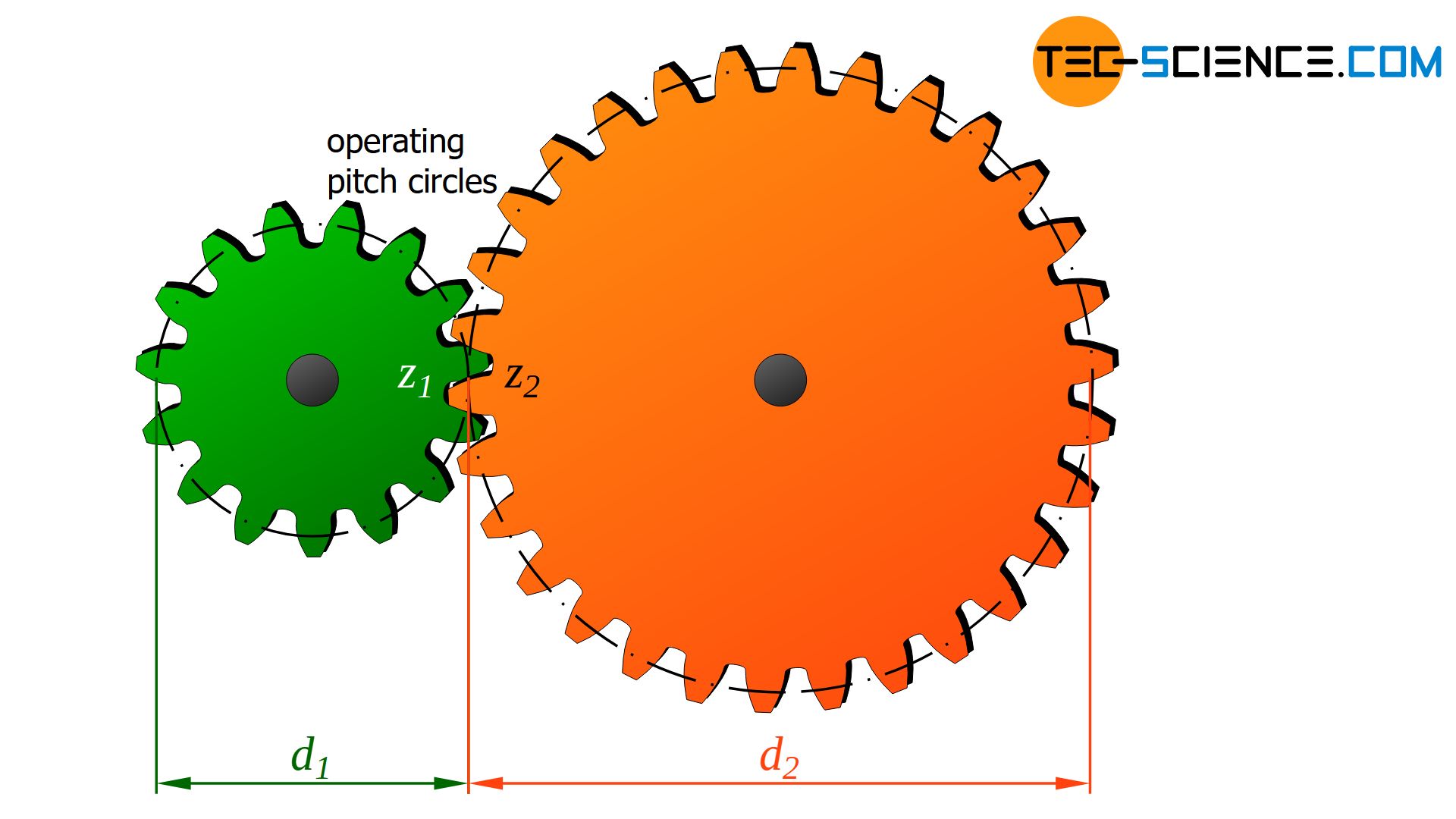
The operating pitch circle diameter is the diameter of imaginary pitch cylinders that roll onto each other without sliding (somewhat a bit imprecise just referred to as pitch circle diameter). Consequently, the circumferential speeds on the operating pitch circle of both gears are identical. The pitch circle diameter of a toothed wheel is ultimately the equivalent of the pulley diameter of belt drives.
The operating pitch circle diameter is the diameter of imaginary cylinders that roll onto each other without slipping!
Belt drive and chain drive
In the case of a friction wheel drive or belt drive (or chain drive), the transmission ratio can be determined by the (inverse) ratio of the respective wheel diameters d:
\begin{align}
\label{rad_uebersetzungsverhaeltnis}
&\boxed{i = \frac{d_2}{d_1}} \\[5px]
\end{align}
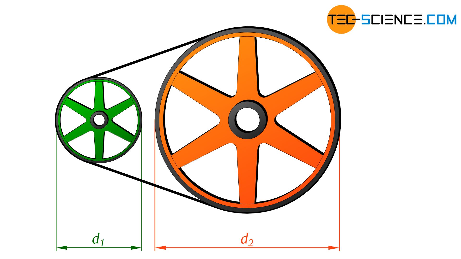
If, for example, the driven wheel is twice as large as the driving wheel, this also applies to the corresponding wheel circumferences. While the driving wheel rotates once, the double-sized wheel rotates only half a turn (either by rolling onto each other in the case of friction wheels or by chains or belts in the case of belt drives or chain drives). The speed is therefore halved and a transmission ratio of i = 2 is again present.
Gear stages
In principle, a certain transmission ratio can be assigned to each wheel pair within a transmission at which the speed changes. The animations above of the gear transmission and the belt transmission show that a transmission usually does not consist of one pair of wheels but of several, each mounted on a different shaft.
Each pair of wheels that mesh with one another represents a so-called gear stage and is characterized by a certain transmission ratio. In general, a gearbox has several gear stages, each with different transmission ratios.
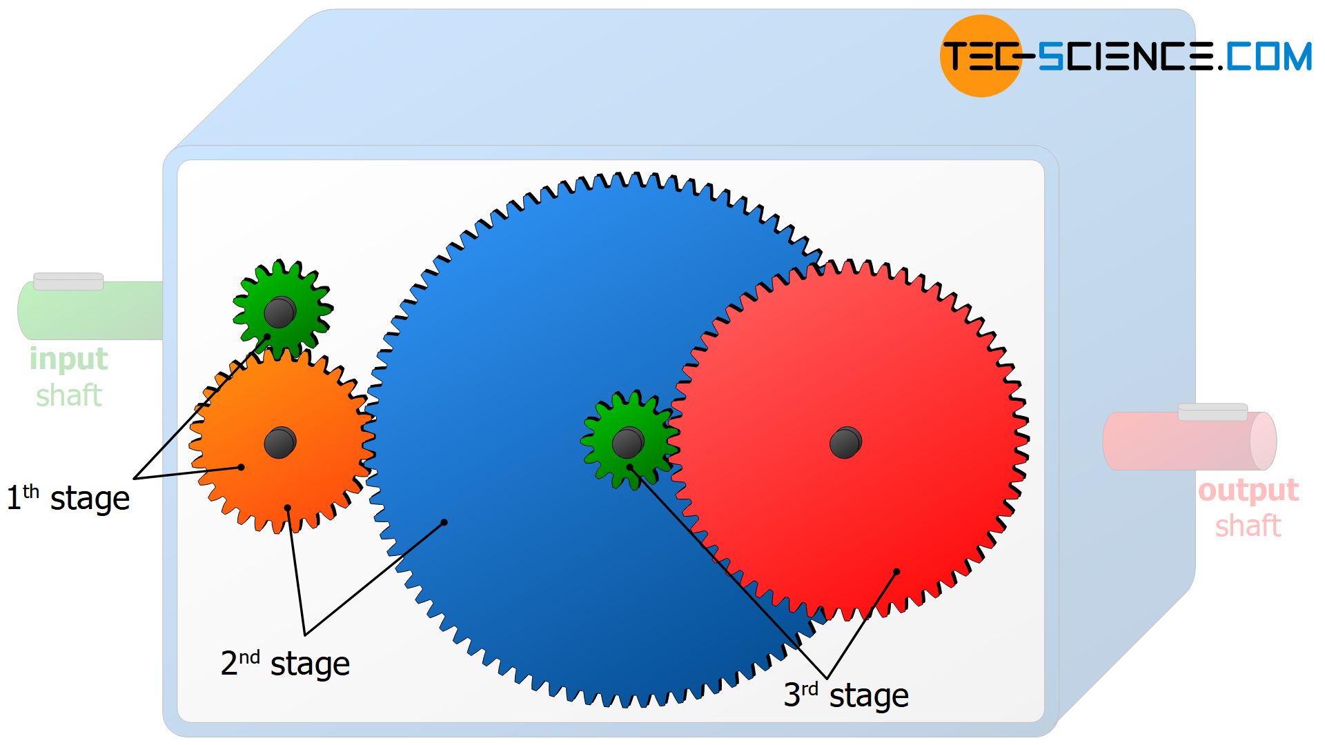
A gear stage is a wheel pairing within a gearbox at which the speed or torque changes!
So when we talk about the transmission ratio of the entire gearbox, we mean the overall transmission ratio, i.e. the transmission ratio between input shaft and output shaft of the whole gear unit! The total transmission ratio it can be calculated by multiplying the individual transmission ratios of the gear stages:
\begin{align}
&\boxed{i_{t} = i_1 \cdot i_2 \cdot i_3 \cdot \dots} \\[5px]
\end{align}
The overall transmission ratio of a gear unit results from the multiplication of the individual transmission ratios of the respective gear stages!
More detailed information on the function and structure of gear stages can be found in the article What is a gear stage?.
Forms of transmission ratios
Gearboxes do not always have to be designed to reduce the speed as is the case in the animations above. In many technical applications, an increase in speed is also desired. This is the case, for example, when driving on highways. In order to move forward as fast as possible, the wheels have to turn as fast as possible. Therefore, it is necessary to increase the speed of the motor shaft by means of a transmission. Then a large gear wheel must then drive a smaller wheel.
In such cases the transmission ratios are smaller than one and one also speaks of a speed ratio. At transmission ratios greater than one, the driven wheel rotates slower than the driving wheel and one speaks somewhat imprecisely of a power ratio. Note, that power in the physical sense ist not transformed but remains constant. Only the torque ist increased at a power ratio. Since the speed is reduced according to the increase of torque, the transmission is often called gear reducer or speed reducer.
A transmission ratio that leads to an increase in speed is called speed ratio. A transmission ratio that leads to an increase in torque is called power ratio.
For example, when starting off with a car in first gear, there is a power ratio with a maximum transmission ratio of about imax = 3.6. Accordingly, the speed is reduced by a factor of 3.6 compared to the motor speed. In top gear, on the other hand, the shiftable motor gearbox has a speed ratio with a minimum transmission ratio of approx. imin= 0.8. The speed is therefore increased by a factor of 1.25 (=1/0.8).
Gearboxes that can change their transmission ratio are also referred to as shiftable transmissions or manual transmissions or, for short, gearshifts. An important characteristic of shiftable transmissions is the increase in the transmission ratio from the minimum to the maximum. The greater this increase is, the larger the speed ranges can be shifted. This increase is also referred to as transmission spread S and is calculated as follows:
\begin{align}
&\boxed{S = \frac{i_{max}}{i_{min}}} = \frac{3.6}{0.8}=4.5 \\[5px]
\end{align}
For the described gearbox, the spread is S = 4.5, which means that the gear ratio can be increased by a factor of 4.5 starting from the minimum value.
The ratio of maximum to minimum gear ratio of a shiftable gearbox is called transmission spread!
Conversion of torque
In the previous section, the conversion of the speeds of two gears was described. Due to the energy conservation, a change in torque is always associated with this speed change (see also article What is a gearbox and what is it used for?)! This is discussed in more detail in the following sections.
Gear drive
The change in torque within a pair of gears becomes clear when one looks more closely at the forces occurring. In the following it is assumed that the driving gear wheel has the torque M1. The adjacent gear wheel is driven by this torque.
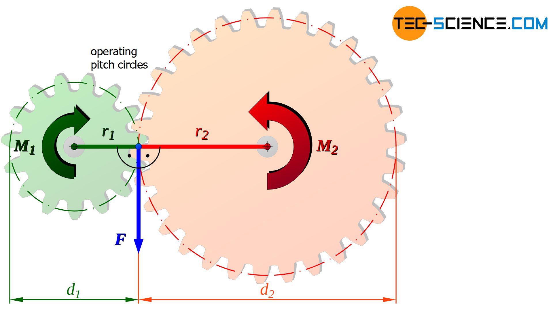
Depending on the diameter d1 of the driving gear, a certain force F is connected to the torque M1. With this force, the tooth flanks on the pitch circle of the driving gear now press against the tooth flanks of the driven gear (also acting on the pitch circle).
The acting force F can be determined from the definition of torque (“torque = force applied x lever arm”). Thus, at a given torque M1, the corresponding force F at the tooth flanks can be determined using the respective pitch circle diameter d1:
\begin{align}
&M_1 = F \cdot r_1 = F \cdot \frac{d_1}{2} \\[5px]
\label{m_t}
&\underline{F = 2 \cdot \frac{M_1}{d_1}} \\[5px]
\end{align}
Note: To simplify matters, it was assumed that the force acts tangentially to the pitch circle, so that force and lever arm (= half pitch circle diameter) are perpendicular to each other. More detailed information on the actual direction of force of involute gears can be found in the corresponding article.
The calculated force F of the driving gear from equation (\ref{m_t}) also acts on the driven gear. However, since the driven gear has a different pitch circle diameter, the force now acts on a changed lever arm (d2/2). Consequently, this is also associated with a change in torque:
\begin{align}
&M_2 = F \cdot r_2 = F \cdot \frac{d_2}{2} ~~~\text{with equation (2)}~~~F = 2 \cdot \frac{M_1}{d_1} ~~~\text{:} \\[5px]
&M_2 = \underbrace{2 \cdot \frac{M_1}{d_1}}_{= F} \cdot \frac{d_2}{2} \\[5px]
\label{m_1}
&\underline{M_2 = M_1 \cdot \frac{d_2}{d_1}} \\[5px]
\end{align}
It is shown by equation (\ref{m_1}) that the torque M2 on the driven gear is proportional to the ratio of the respective pitch circle diameters d2/d1. The larger the driven gear in relation to the driving gear, the greater the increase in torque will be.
For gears, the pitch circle diameter is directly proportional to the number of teeth. Because with a double (pitch circle) diameter, the gear wheel circumference is twice as large and thus also offers space for twice the number of teeth.
If the driven gear has twice as many teeth as the driving gear, the associated double lever arm ultimately doubles the torque. In this respect, the torque increase can also be expressed by the ratio of the number of teeth:
\begin{align}
\label{m_2}
&\underline{M_2 = M_1 \cdot \frac{z_2}{z_1}} \\[5px]
\end{align}
The ratio of pitch circle diameters in equation (\ref{m_1}) or ratio of the number of teeth in equation (\ref{m_2}) corresponds to the transmission ratio i in equation (\ref{zaehne_uebersetzungsverhaeltnis}). This means that the change in torque can also be expressed directly by the transmission ratio:
\begin{align}
\label{1}
&\boxed{M_2 = M_1 \cdot i }~~~\text{with}~~~\underline{i = \frac{z_2}{z_1}= \frac{d_2}{d_1}=\frac{n_1}{n_2}} \\[5px]
\end{align}
Note that the transmission ratio is defined as the ratio of the rotational speeds of driving gear to driven gears. Thus, for the speed n2 of the driven gear at a certain transmission ratio i the following relationship to the original speed n1 applies:
\begin{align}
\label{2}
&\boxed{n_2 = \frac{n_1}{i} } \\[5px]
\end{align}
As the torque increases according to equation (\ref{1}) at a certain transmission ratio, the speed decreases to the same extent according to equation (\ref{2}) and vice versa. This is ultimately a direct consequence of the law of energy conservation. In the section “Energetic approach”, this relationship is explicitly derived using the law of energy conservation.
As the speed is increased by a gearbox, the torque is reduced to the same extent and vice versa!
Note that the equations above apply only to the ideal case of a non-dissipative gearbox. In general, friction cause a reduction in power and thus a reduction in the theoretically calculated torque for the driven shaft. These power losses are taken into account by a gear efficiency \(\eta_g\):
\begin{align}
&\boxed{M_2 = M_1 \cdot i \cdot \eta_g } \\[5px]
\end{align}
For the calculation of the speed, however, the gear efficiency does not play a role, since the speed conversion results from the number of teeth (the teeth cannot penetrate each other and thus produce a lower speed than is preset by the ratio of the number of teeth).
Belt drive
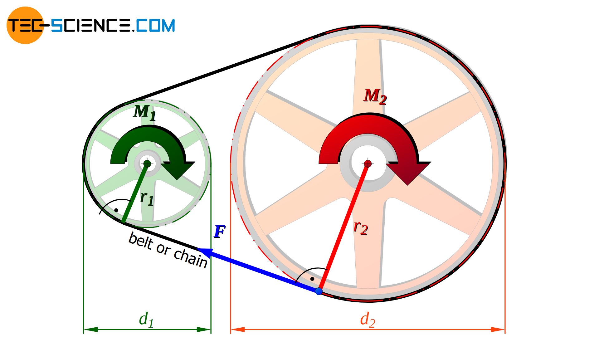
Also with traction mechanism, the change of torque takes place in a similar manner as in gear transmissions. Depending on the diameter d1, the driving wheel with the torque M1 pulls on the belt or the chain with a certain force F according to equation (\ref{m_t}).
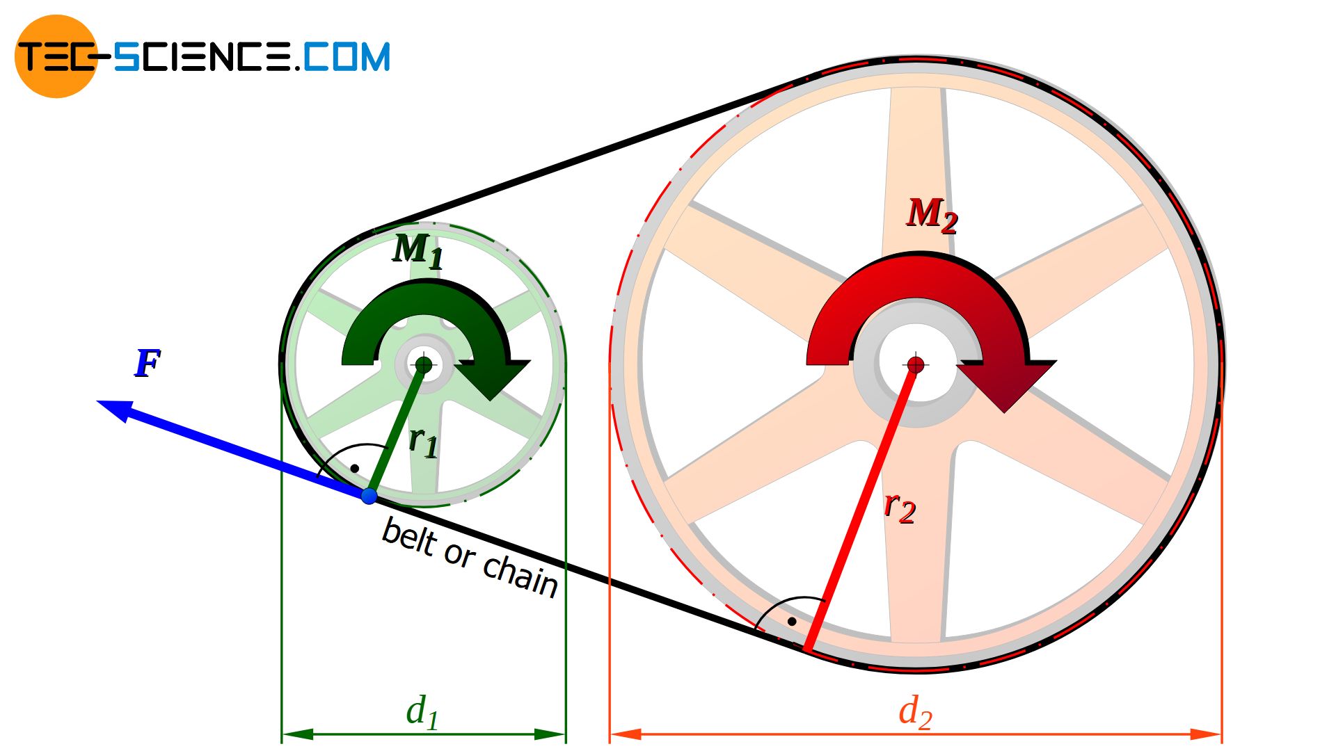
The same force F also acts on the driven wheel through the belt or the chain. Since the diameter d2 of the driven wheel differs from the driving wheel, a change in torque M2 results. The changed torque M2 at the driven wheel again results from equation (\ref{m_1}). The exact forces acting on belt drives are described in more detail in separate articles.
 are there?")
 and what is it used for?")
")

