The shape of the flank of a cycloidal gear corresponds to a cycloid constructed by rolling a rolling circle on a base circle.
Construction of a cycloid
The shape of the flank of a cycloidal gear is a so-called cycloid. A cycloid is constructed by rolling a rolling circle on a base circle. A fixed point on the rolling circle describes the cycloid as a trajectory curve. A distinction can also be made between an epicycloid and a hypocycloid. An epicycloid is obtained when the rolling circle is rolled on the outside of the base circle. If, on the other hand, the rolling circle is rolled on the inside of the base circle, this is referred to as a hypocycloid. Accordingly, rolling circles can be divided into inner rolling circles (-> hypocycloids) and outer rolling circles (-> epicycloids).
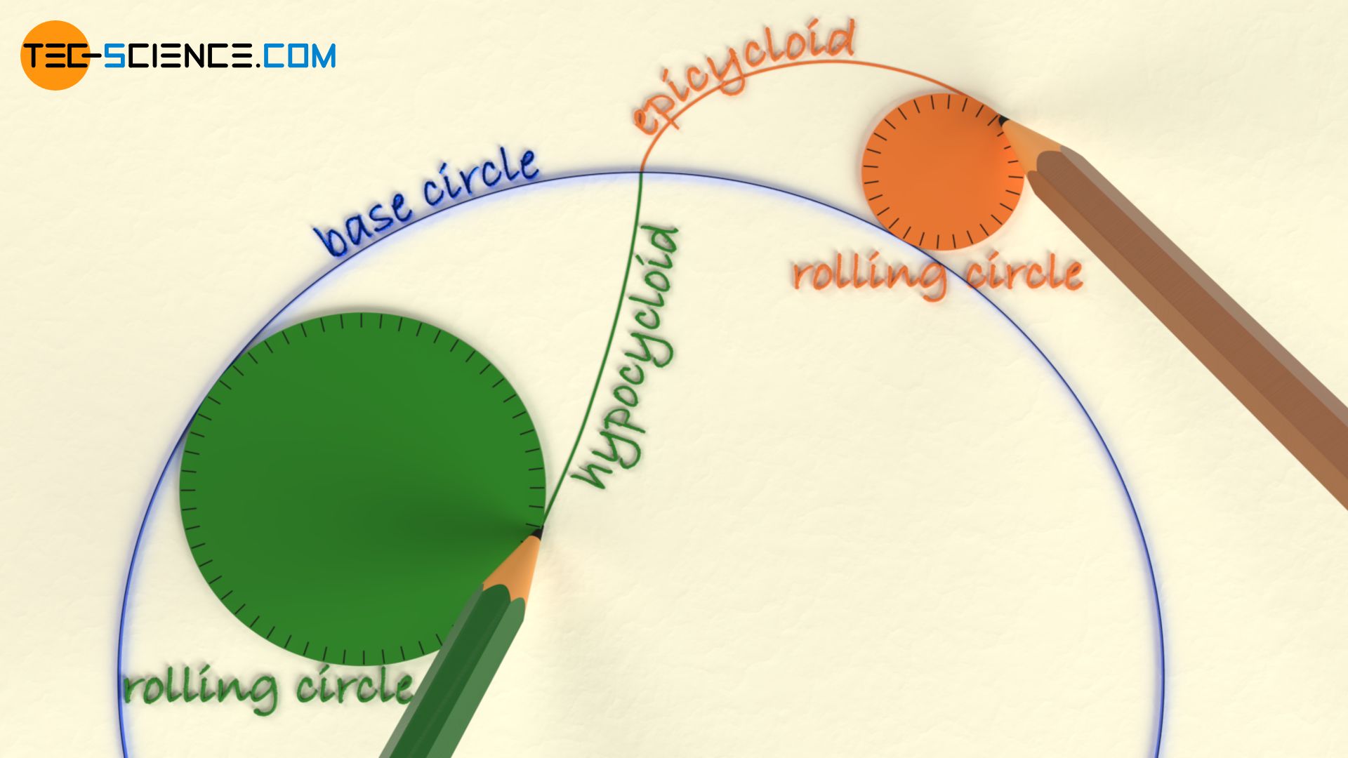
A cycloid is obtained by rolling a rolling circle on a base circle! Epicycloids result from rolling on the outside of the base circle and hypocycloids from rolling on the inside of the base circle!
Construction of cycloidal gears
With cycloidal toothing, the addendum flank of the tooth has the shape of an epicycloid and the dedendum flank the shape of a hypocycloid. The inner rolling circle with which the hypocycloid is constructed generally does not correspond to the outer rolling circle with which the epicycloid is constructed, i.e. different rolling circles are used.
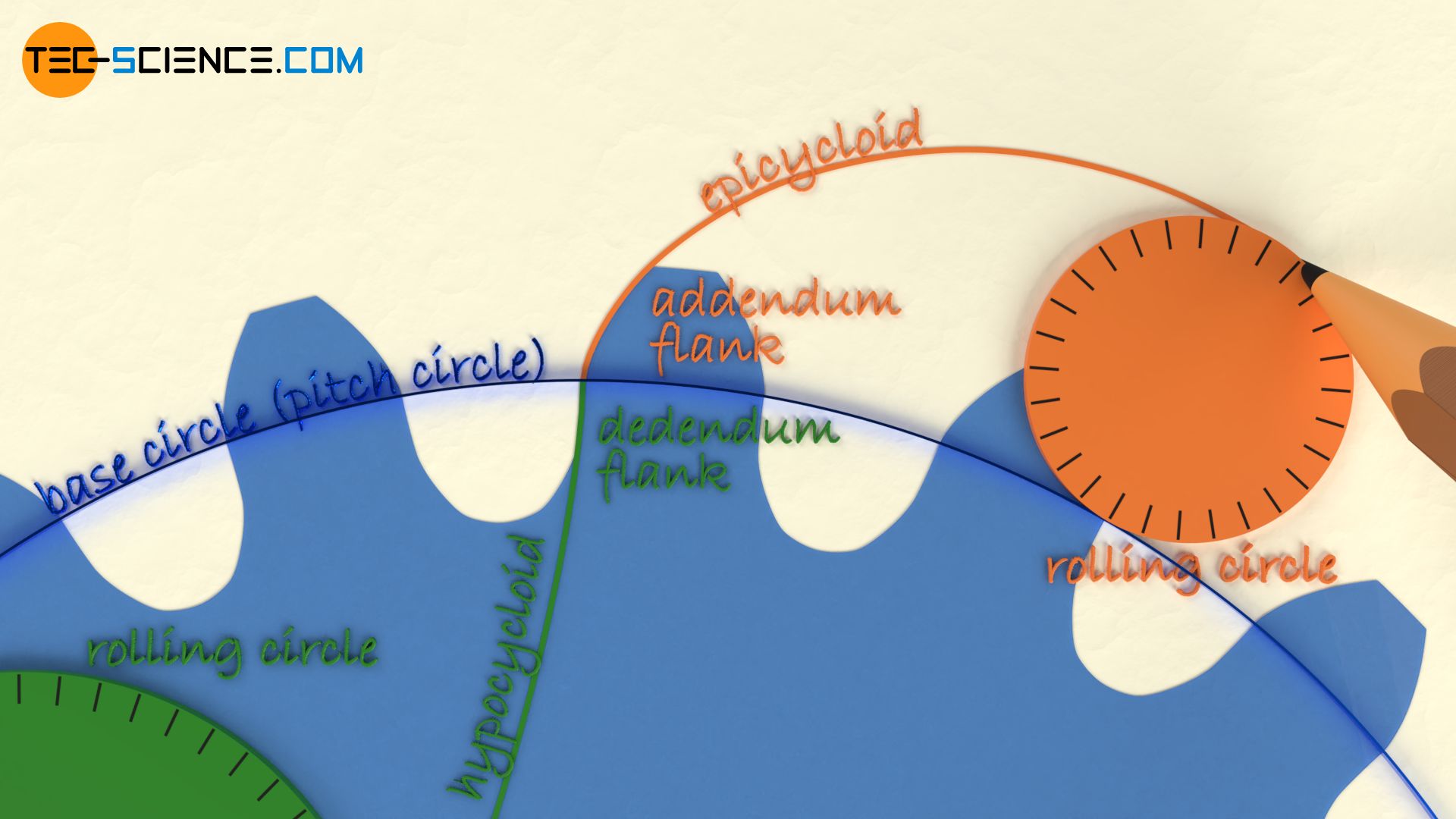
So that the teeth of two cycloidal gears can mesh correctly without interference, the outer rolling circle which is used for the construction of the addendum flank (epicycloid) of one gear, is then used as the inner rolling circle for the construction the dedendum flank (hypocycloid) of the mating gear! Conversely, the inner rolling circle for the construction of the dedendum flank (hypocycloid) of one gear corresponds to the outer rolling circle for the construction of the addendum flank (epicycloid) of the mating gear. This connection of the identical rolling circles ensures the validity of the fundamental law of gearing, which is necessary for a constant transmission ratio.
The rolling circle for the construction of the addendum flank of one gear is used for the construction of the dedendum flank of the mating gear and vice versa!
Since a rolling circle is always used to construct the tooth shape of two gears to be mated, cycloidal gears are always specially matched to each other. A cycloidal gear cannot be replaced easily by a gear with a different number of teeth as is the case with involute gears. Such a interchangeability of gears with cycloidal toothing is only possible if the rolling circles are always chosen identically and are only related to the base circle of the “main gear”.
Cycloidal gears must always be specially matched to each other and can generally not be exchanged at will!
The rolling circles are generally matched to the base circles, i.e. they are in a certain ratio to each other, since the ratio of rolling circle diameter to basic circle diameter determines the shape of the cycloid and therefore the shape of the tooth flank. All cycloids with the same rolling circle to base circle ratio are geometrically similar to each other. A ratio of about 1:3 for rolling circle diameter to base circle diameter is often found (the rolling circle diameter refers to the inner rolling circle for the construction of the hypocycloid!).
The base circle of a cycloidal gear always corresponds to the standard reference pitch circle which is in the case of cycloidal gears identical to the operating pitch circle. The contact point of the pitch circles corresponds to the pitch point. The pitch circle diameter d is determined analogously to an involute gear by multiplying the module m and the number of teeth z:
\begin{align}
&\boxed{d = m \cdot z} \\[5px]
\end{align}
The base circle of a cycloidal gear corresponds to the pitch circle!
The addendum diameter da (tip diameter) of a cycloidal gear can also be determined analogously to an involute gear:
\begin{align}
&\boxed{d_a = d + 2 \cdot m} \\[5px]
\end{align}
Special types of cycloids
Special case of a hypocycloid: a straight line
A special case in the tooth form of cycloidal gears arises when the rolling circle corresponds to half the base circle. In this case, straight foot flanks are obtained which extend radially outwards. Such a toothing is also called “clock toothing“, since it was often found in clockworks in the past (nowadays, however, the circular arc toothing is mostly used).

Straight dedendum flanks are obtained if the rolling circle diameter for the construction of the hypocycloid corresponds to half the base circle diameter!
Note that a hypocycloid can only be constructed if the rolling circle diameter is smaller or, in extreme cases, equal to the base circle of the gear (in such an extreme case one also speaks of a point tooth form). Otherwise no rolling can take place on the inside of the base circle! However, this restriction does not apply to the construction of an epicycloid; in this case, rolling circles of any size can be used. An important special case will be discussed in more detail in the next section.
Special case of an epicycloid: an involute
An important special case of an epicycloid is obtained when the outer rolling circle is made larger and larger. In extreme cases, the result is a circle with an infinitely large diameter, which corresponds to a rolling straight line due to the infinitely small curvature. The resulting epicycloid is then called an involute and the toothing is correspondingly called an involute toothing.

Involute toothing is a special case of cycloidal toothing with a rolling circle of infinite diameter.
Pros and cons of cycloidal gears
The cycloidal shape of a tooth leads to less wear of the tooth flanks during meshing and thus to lower friction losses in comparison to the involute shape. The reason for this is the lower contact pressure (lower hertzian contact stress), since a convex and a concave flank always meet in mesh and “nestle” up against each other, so to speak.
Furthermore, cycloidal gears can be produced with a significantly lower number of teeth without undercutting compared to involute gears. In this way, gears with only three or even two teeth can theoretically be produced.
The lower friction and the low number of minimum teeth are the main reasons why cycloidal gears are/were often found in clocks.
Despite the mentioned advantages of cycloidal gears, involute gears are still the most commonly used type of gears in mechanical engineering! The reason is the relatively simple production of an involute shape (straight tool flanks) compared to a cycloidal shape (curved tool flanks).
Furthermore, cycloidal gears are very sensitive to an inaccurate adjustment of the centre distance, which then leads to a change in the transmission ratio. For these reasons, cycloidal gears are hardly found in mechanical engineering but are only used in special cases such as in the watch industry, for roots type blowers or for the drive of gear racks.


