The mechanical power is determined by the force and speed or by the torque and rotational speed.
Introduction
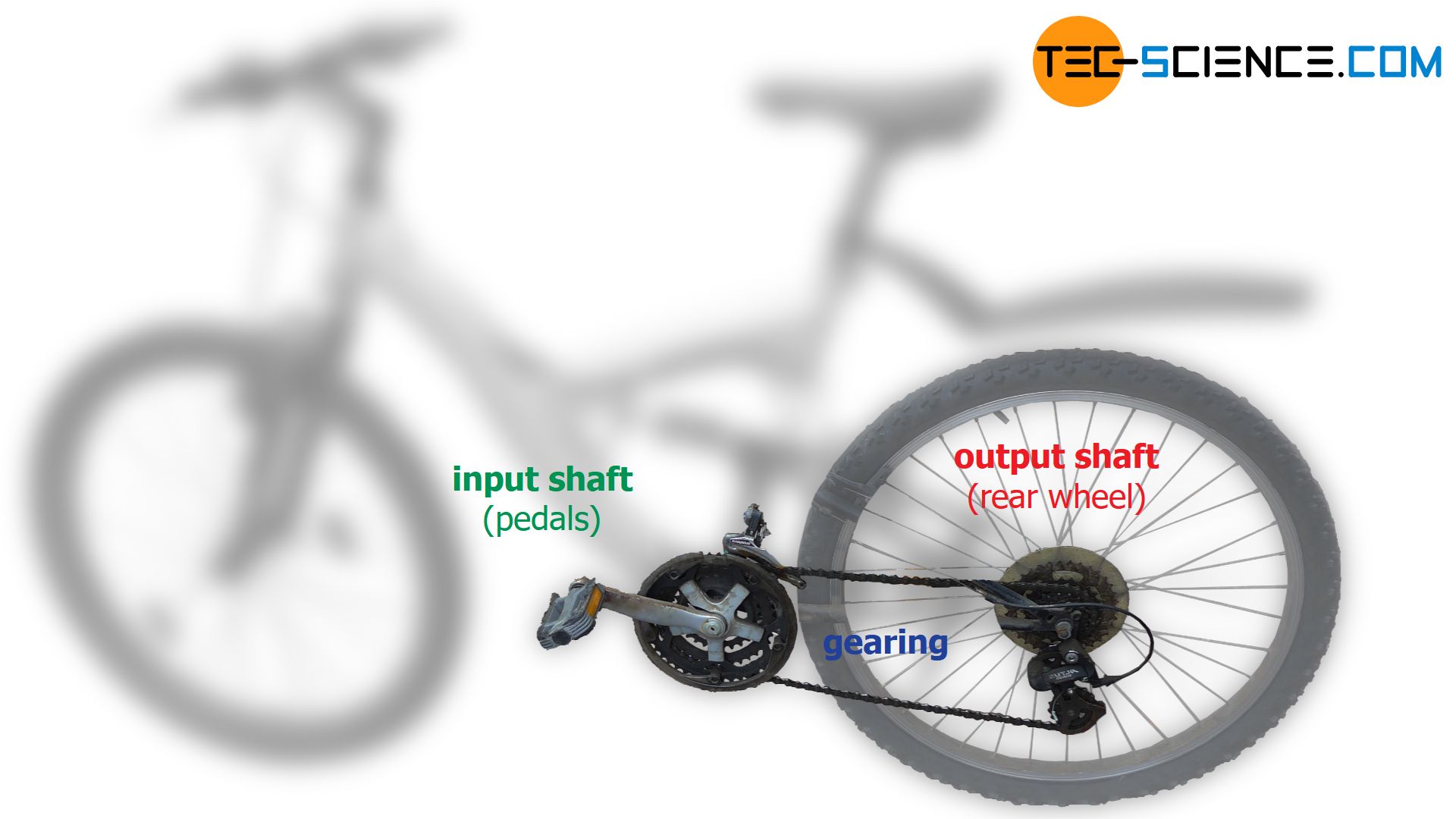
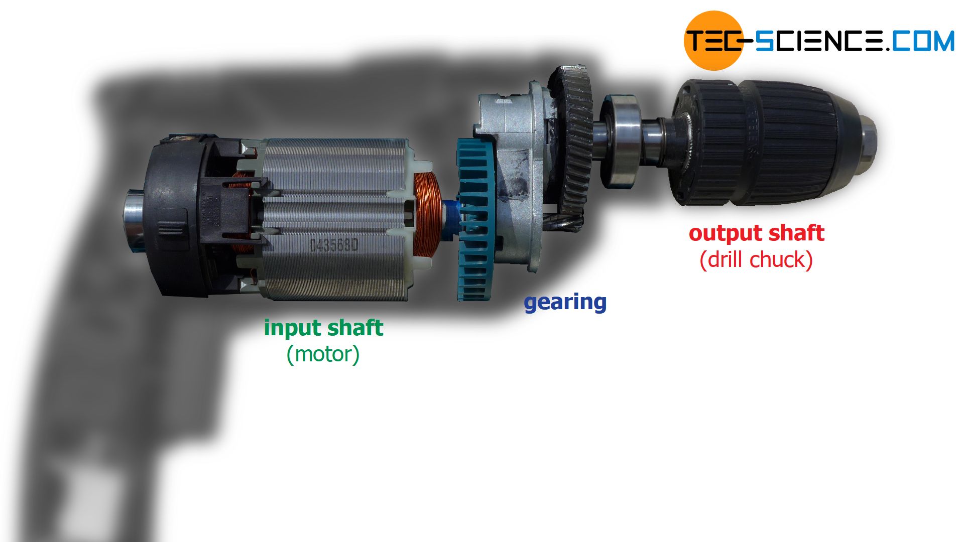
The term power (in the physical sense) plays an important role in transmissions, since they have to be dimensioned according to the motor performance. For this reason, the following article discuss the term power in more detail. In connection with gears, the question of mechanical power at the output shaft (e.g. at the drill chuck of a drill or at the rear wheel of a bicycle) always seems to be an interaction between two decisive parameters. Namely the
- translational speed (velocity) and force at translational motions; respectively the
- rotary speed and torque at rotary motions.
Everyday experience shows that for a given drive power (motor power) the gearbox can only ever change one parameter at the expense of the other parameter. For example, one will not be able to ride up a steep hill with a bicycle or a car (when a great force is required) at such a high speed compared to a flat road. The speed of the driven wheels must be reduced accordingly in favor of the force. You have to literally “shift down a gear”. Only after overcoming the ascent, when no great force is required anymore, one can pick up speed again with a higher gear.
Even a drill in the highest gear may not be able to develop the torque required to drill a large bore. At this point, too, a lower gear must be used in favour of the torque and at the expense of the speed.
Definition of mechanical power
So while an increase of force can only take place at the expense of velocity, an increase of speed results in an inevitable reduction of force. This situation is ultimately a direct consequence of the principle of energy conservation (more details on this see article operating principle).
To understand this, a basic knowledge of the terms power and work is required. For this reason, the following sections describe these terms in more detail.
Physically, the mechanical power P of a moving body is defined by the work or energy W transferred within a certain time Δt:
\begin{align}
\label{def_leistung}
&P = \frac{W}{\Delta t} \\[5px]
\end{align}
The more work is done within a certain period of time, the greater the power. The work W, by definition, results from the product of force F and distance Δs through which the force acts (provided force and distance are rectified):
\begin{align}
\label{def_arbeit}
&W = {F} \cdot {\Delta s} \\[5px]
\end{align}
These basic terms are used in the following sections to look more closely at mechanical power during translational and rotational motions.
Power during translational motions (linear motions)
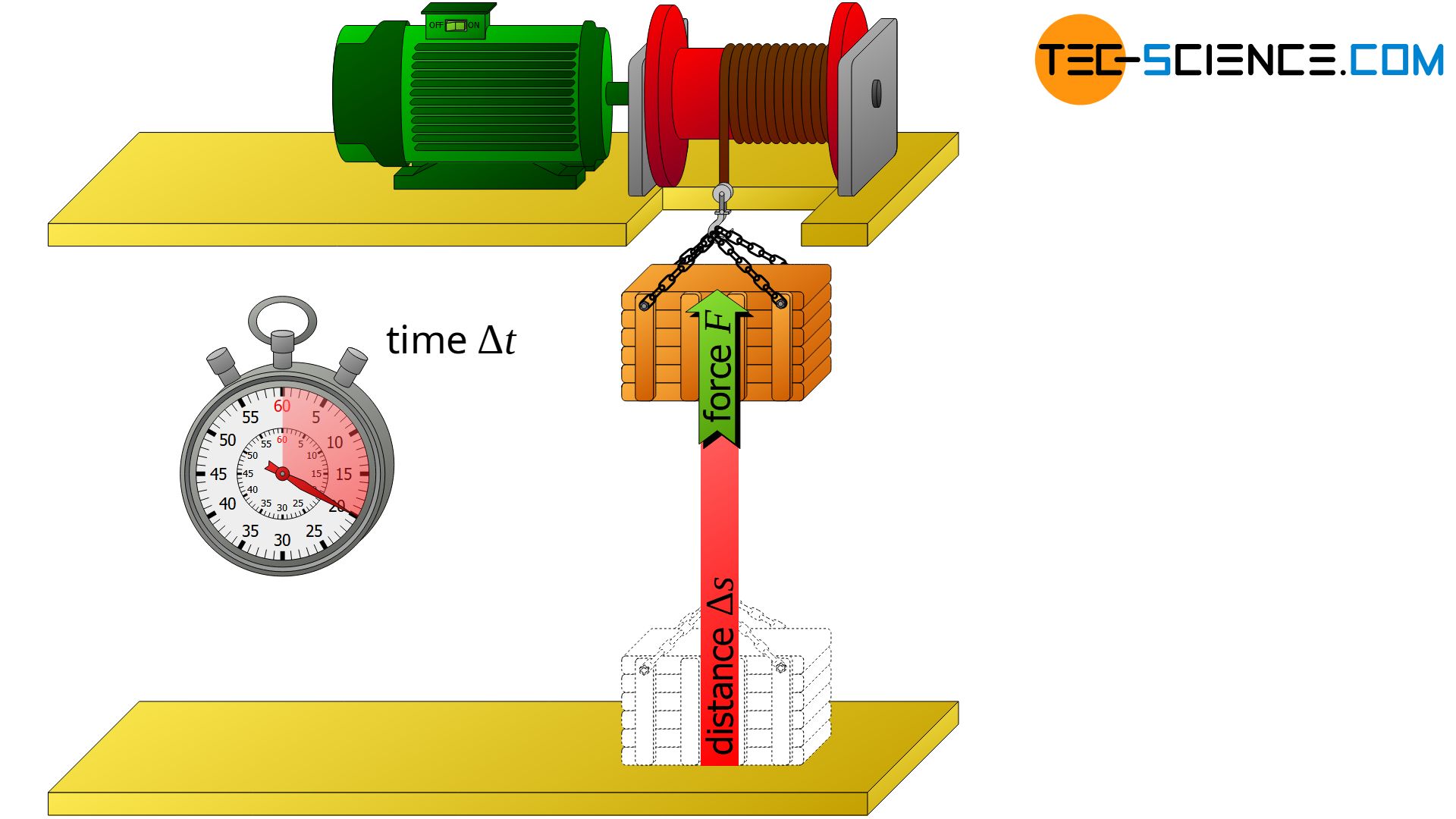
For the power of translational motions (linear motions) there is a certain connection between force and velocity. This will be shown in the following sections using a winch driven by a motor as an example.
Derivation
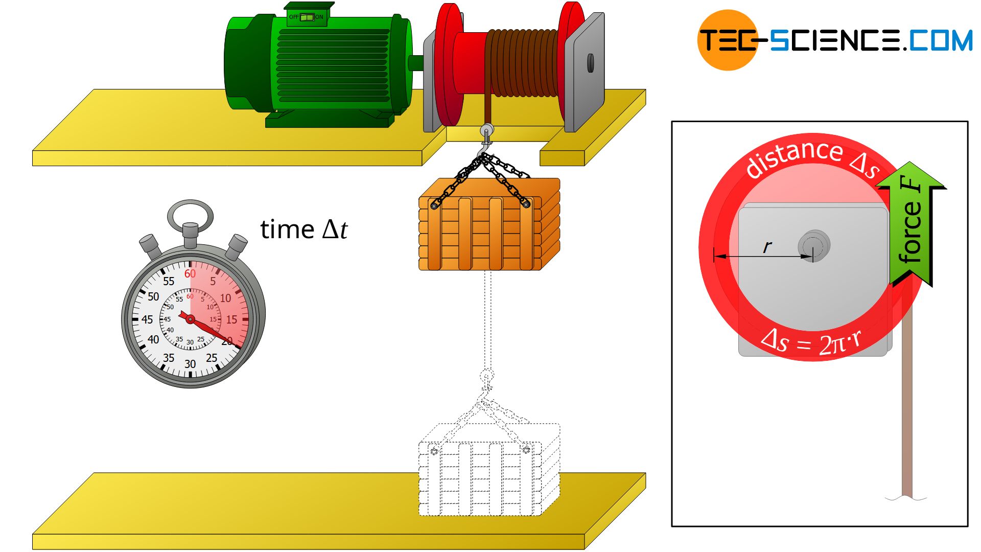
The winch pulls a crate upwards with constant velocity v and constant force F. The crate is raised by the displacement Δs within the time Δt. The work W of the winch performed during this time Δt results by definition from the product of applied force F and travelled distance Δs:
\begin{align}
\label{arbeit}
&W = F \cdot \Delta s \\[5px]
\end{align}
This work was obviously done during lifting and thus within the lifting time Δt. From the definition of the power, the converted mechanical power of the winch P can then be determined as follows:
\begin{align}
\label{leistung_trans}
&P = \frac{W}{\Delta t} = \frac{F \cdot \Delta s}{\Delta t} = F \cdot \underbrace{ \frac{ \Delta s}{\Delta t}}_{=v} = F \cdot v \\[5px]
\end{align}
During this mathematical transformation, the fact was used, that the quotient of the distance covered Δs and the time required Δt corresponds to the velocity v of the raised box.
The required mechanical power P to drive a component with constant velocity v by the force F results from the product of both quantities:
\begin{align}
\label{translationsleistung}
&\boxed{P = F \cdot v} \\[5px]
\end{align}
Influencing the motion by a transmission
In this example, the required mechanical power is supplied by the motor and transmitted directly to the winch. In principle, motors cannot provide any amount of power. Rather, the performance is limited depending on the engine design. If only a certain motor power P is available, then after transforming the equation (\ref{translationsleistung}) it becomes immediately apparent that a higher force F can obviously only be achieved with a correspondingly lower speed v.
\begin{align}
\label{kraft}
&F = \frac{P}{v} \\[5px]
\end{align}

A heavier crate can therefore only be lifted with a higher force if the speed is reduced accordingly. On the other hand, at given engine power P a lighter box (when only a lower force F is necessary for pulling up) can be lifted with higher speed v.
\begin{align}
\label{geschwindigkeit}
&v = \frac{P}{F} \\[5px]
\end{align}
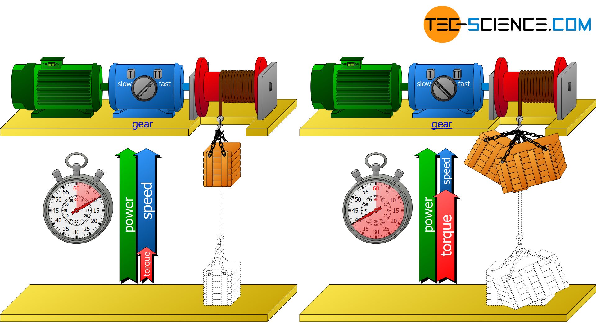
This is exactly where transmissions come into play. They take control of the power in favour of a greater force or in favour of a greater speed. A transmission cannot increase both quantities at the same time, as this would require an increase in power. However, the power is fixed by the motor and cannot be changed even by a gearbox.
Transmissions do not change the mechanical power but only the speed-force ratio, which is behind a certain power! This means either a higher force at lower speed or a higher speed at lower force.
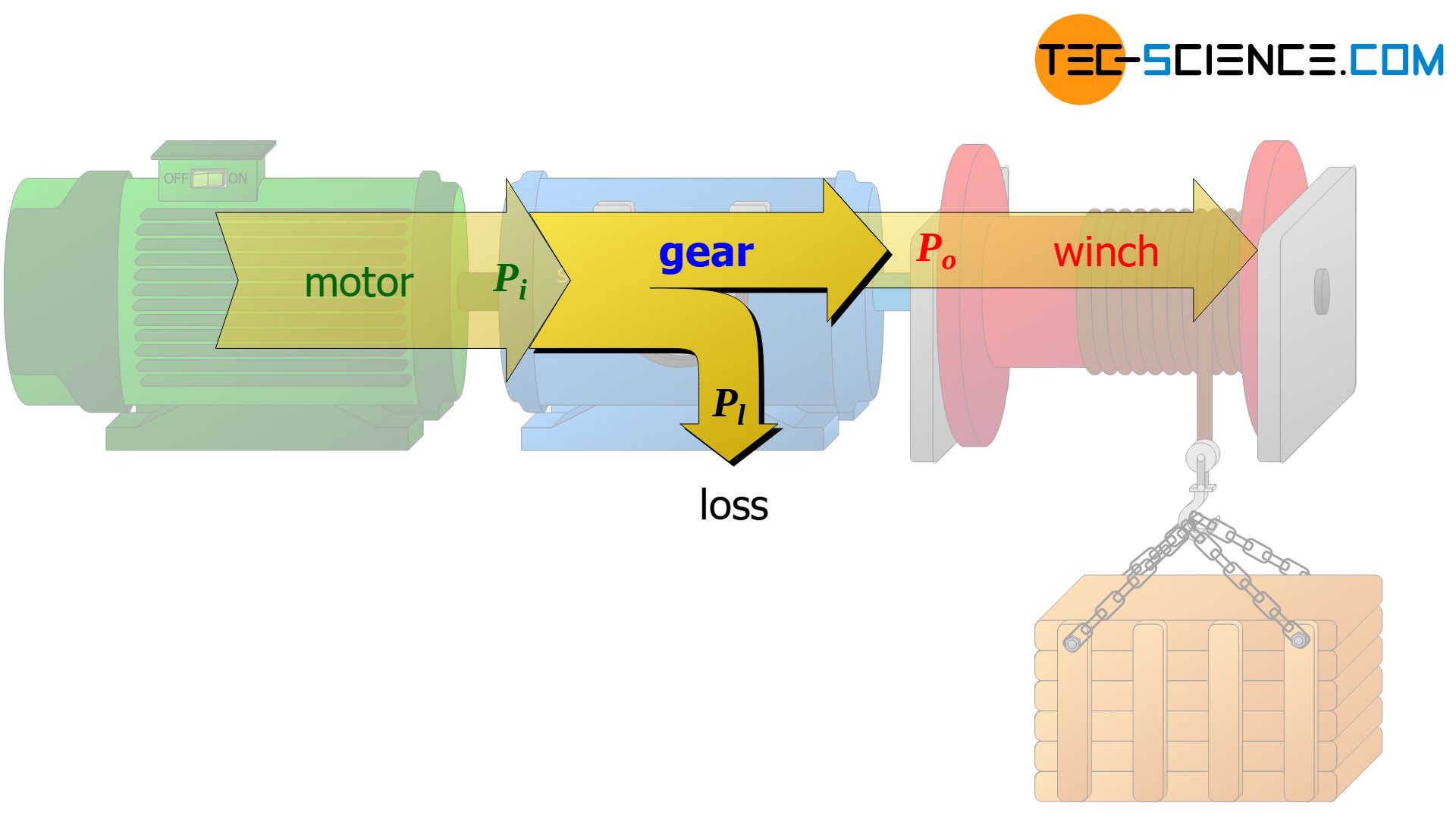
In an ideal case, the input power Pi supplied by the motor is completely transferred by the gear to the gearbox output (Po). In reality, however, power losses Pl occur in the gear unit due to friction. These are expressed by the transmission efficiency ηg (≤ 1):
\begin{align}
\label{getriebewirkungsgrad_trans}
&\boxed{P_{o} = P_{i} \cdot \eta_g} \\[5px]
\end{align}
Power during rotary motions (circular motions)
The knowledge of the relationship between force and velocity for translational motions can be transferred to rotary motions. For this purpose, the winch described in the previous section is considered again. This time, however, the circular motion of the rope winch and the acting force is considered in more detail.
Derivation
The winch pulls the rope with the force F along the arc length Δs during winding. The distance covered Δs, however, no longer describes a straight line but an arc of a circle. However, the force is always parallel to the curved path at every point. This means that the formula for the work W=F⋅Δs can be applied again.
\begin{align}
\label{arbeit_01}
&W = F \cdot \Delta s \\[5px]
\end{align}
During a whole revolution, the winch wound the rope once completely around its circumference, i.e. the force F acted along the circular path Δs=2π⋅r. The work W done by the winch during this rotation is then finally determined as follows:
\begin{align}
\label{arbeit_02}
&W = F \cdot 2 \pi r \\[5px]
\end{align}
The time Δt for this single turn is also called period T (period = “time duration per revolution”). Therefore, within the time T the work W=F⋅2π⋅r was done, leading to the following power P:
\begin{align}
\label{leistung_rot}
&P = \frac{W}{\Delta t} = \frac{F \cdot 2 \pi r}{T} = 2 \pi \underbrace{\frac{1}{T}}_{=n} \cdot \underbrace{ F \cdot r}_{=M} = 2 \pi \cdot n \cdot M \\[5px]
\end{align}
The product of acting force F and perpendicular aligned lever arm r ultimately corresponds to the effective torque M at the winch drum with which the rotary motion is carried out. Therefore both variables can be combined to the torque M.
The formula can be interpreted even further, considering the meaning of the expression 1/T. While the period T indicates “time per revolution”, the inverse of the period 1/T therefore indicates “revolutions per time”. This corresponds to the rotational speed n (or frequency f) of the rotational motion! The following relationship between the rotational speed n (or frequency f) and the period T applies:
\begin{align}
\label{drehzahl}
&n = \frac{1}{T} \\[5px]
\end{align}
Note: In principle, the term rotational speed (denoted by n) is equivalent to the term rotational frequency or frequency for short (denoted by f). However, while the term rotational speed is often used in connection with the technical unit “revolutions per minute”, the rotational frequency f is usually used in connection with the physical unit “revolutions per second”. Note that even if the symbol n is used in equations, the unit 1/s must always be used!
The mechanical power P of a component driven at constant rotational speed n by torque M results from the product of both quantities multiplied by the constant factor 2π:
\begin{align}
\label{rotationsleistung}
&\boxed{P = 2 \pi \cdot M \cdot n} \\[5px]
\end{align}
Influencing the motion by a transmission
In the present case, the power required for the rotation of the winch drum is supplied directly by the motor. Since motor performance is always limited, a motor cannot generate any desired torque. However, higher torques are required when lifting larger loads. In such a case, a gearbox must be interposed, which increases the torque M at a given motor power P. After transforming the equation (\ref{rotationsleistung)) it becomes immediately obvious that a higher torque inevitably results in a lower speed n. The crate can no longer be lifted so quickly.
\begin{align}
\label{getriebe}
&n = \frac{P}{2 \pi \cdot M} \\[5px]
\end{align}
If, on the other hand, a low load is to be lifted with a correspondingly reduced torque M, the torque can be reduced by the gear unit in favor of the speed n. In this case, the crate can be lifted faster.
Again, note that the power P is fixed by the motor and cannot be changed by the transmission! A gearbox can only control the ratio of torque and speed! The power supplied by the motor is therefore converted by the gearbox only in favor of a higher torque and thus at the expense of the speed (or vice versa).
Transmissions do not change the mechanical power but only the torque-speed ratio, which is behind a certain power! This means either a high torque at lower speed or a higher speed at lower torque.
In principle, both the torque and the speed can of course be increased at the same time by a higher motor power. But after all, the engine will not be able to deliver unlimited power. Finally, the power limit is reached and a further increase in torque can only be achieved by a gearbox that inevitably reduces the speed. Moreover, for economic reasons, increased engine power does not always make sense, as such motors are usually more expensive than engines with lower power values.
Connection between translational and rotational motion
At this point, the formula (\ref{leistung_rot}) for calculating the power of rotational motions is to be interpreted differently:
\begin{align}
&P = \underbrace{\frac{2\pi}{T}}_{= \omega} \cdot M = \omega \cdot M \\[5px]
&\boxed{P = M \cdot \omega} \\[5px]
\end{align}
In this equation, the term 2π/T ultimately indicates the angle travelled in radians per time unit:
- one full rotation = angle 2π
- time required = period T
Thus the term 2π/T can be interpreted as angular velocity ω. The angular velocity ω is connected to the rotational speed n as follows:
\begin{align}
\label{winkelgeschwindigkeit}
&\boxed{\omega = \frac{2\pi}{T}} = 2\pi \underbrace{\frac{1}{T}}_{= n} = 2 \pi n \\[5px]
&\boxed{\omega = 2 \pi n} \\[5px]
\end{align}
When comparing the power formulas for a translatory motion and a rotatory motion, a direct analogy becomes apparent. The analog quantity to the force for translational motions corresponds to the torque for rotary motions and the quantity of translational speed corresponds to the angular speed. The product of the respective quantities then corresponds to the translational power or rotational power.
| translational motion | rotational motion | |
| “motion intensity” | force F | torque M=F⋅r |
| “motion speed” | translational velocity v | angular velocity ω=v/r |
| “power” | P=F⋅v | P=M⋅ω |
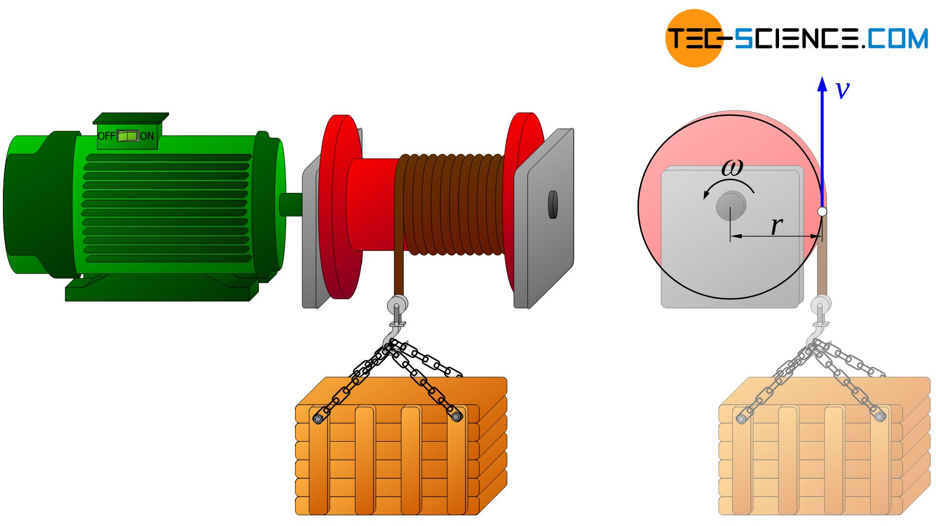
The lifting of a crate using a winch is considered again. In this case, the winch drum rotates and the crate translates. However, both motions are obviously not independent of each other. If, for example, the rotational speed of the winch drum is increased, the translational speed of the box also increases. There is obviously a certain relationship between angular velocity and translational velocity.
This relationship can be established through the mechanical power. The rotational power Prot of the winch drum is completely transferred to translational power Ptra of the crate. If the respective formulas are equated, the following relationship between the angular velocity ω and the translational velocity v applies:
\begin{align}
\label{zusammenhang}
&P_{tra}= P_{rot} \\[5px]
&F \cdot v = M \cdot \omega ~~~~~\text{mit }~~~ M = F \cdot r ~~~\text{folgt:}\\[5px]
&F \cdot v = F \cdot r \cdot \omega \\[5px]
& \boxed{v = \omega \cdot r} \\[5px]
\end{align}
The translational velocity v can be understood as the speed at which a rotating point moves at a distance r from the axis of rotation. A point on the winding rope of the winch drum will rotate at the same speed as the crate is pulled up. Torque and angular velocity of rotational motions are thus directly related to the force and translational velocity of translational motions through the radius (see table above).
Rotational and translational motions are related to each other through the radius!
 are there?")
 and what is it used for?")
")

 work?")