Undercut occurs when the number of teeth of a gear is too small. An undercut leads to a weakening of the strength of the tooth!
Undercut
Undercut due to manufacturing process
The animation below shows schematically the manufacturing process of three gears with different numbers of teeth by hobbing. It can be seen that if the number of teeth is too small, the hob obviously undercuts the tooth root. This is due to the fact that in the case of small gears, the cutting edges of the hob cutter engage relatively far into the gear (in the case of the red gear, up to about half the radius). This causes the tooth to be very strongly undercut during the rotation of the gear.

Therefore, undercuts must always be avoided, i.e. the number of teeth must not fall below a minimum.
Undercut occurs when the number of teeth of a gear is too small. An undercut leads to a weakening of the strength of the tooth!
Undercut due to meshing
An undercut during gear cutting occurs not only with hobbing but with shaping or planing as well. Although an undercut could be avoided by other manufacturing processes such as form cutting or broaching, the undercut is also absolutely necessary for functional reasons. If an undercut were not present with small gears, the teeth would interfere! As the animation below shows, the teeth of the red gear must be undercut by the teeth of the green gear for meshing.
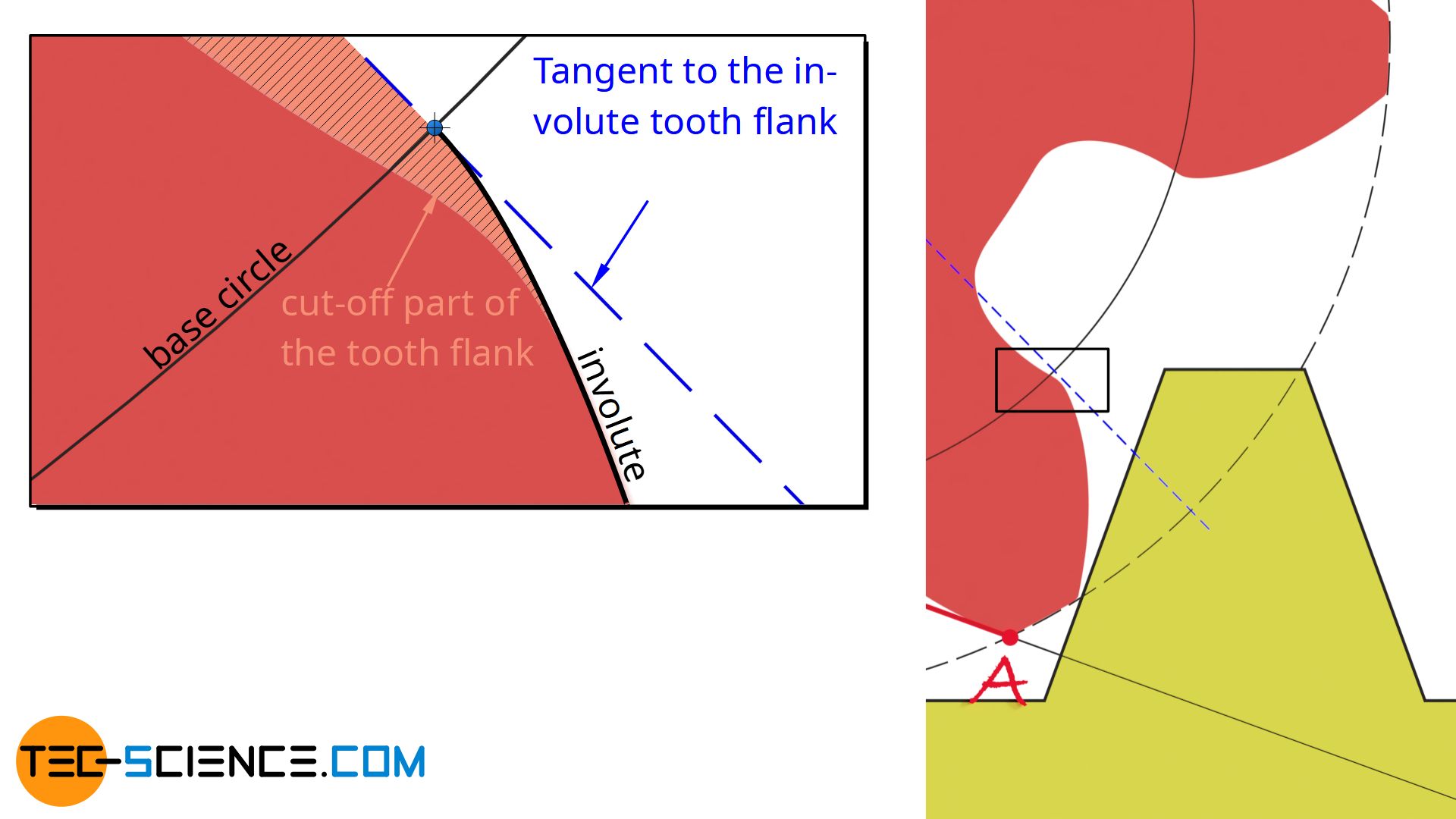
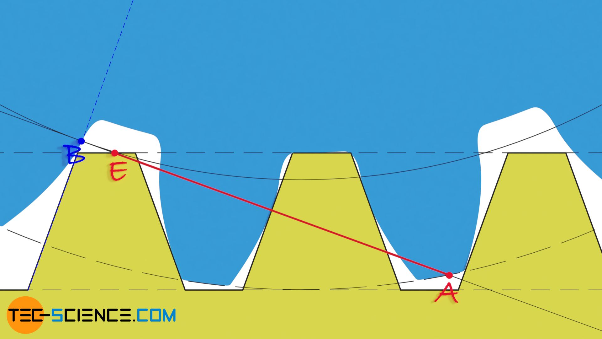
An undercut not only weakens the respective tooth but also shortens the line of contact. The undercut cuts off part of the involute tooth flank. The tooth flanks thus lose contact with each other (already at point E) well before the actual end of engagement (point E’). The enlarged figure shows that the flank contact after point E is already no longer present. The line of action is shortened accordingly.
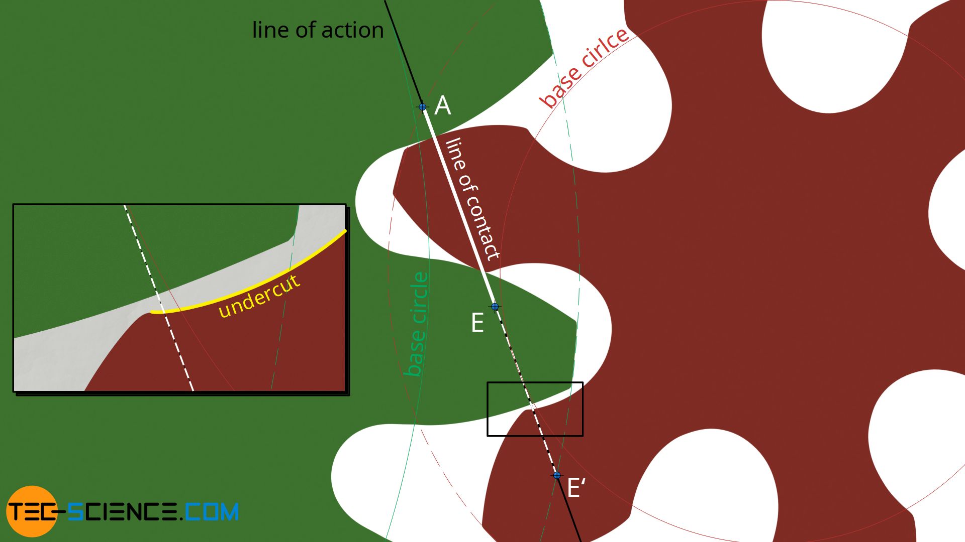
An undercut leads not only to a weakening of the tooth but also to a shortening of the line of contact!
Minimum number of teeth to avoid undercut
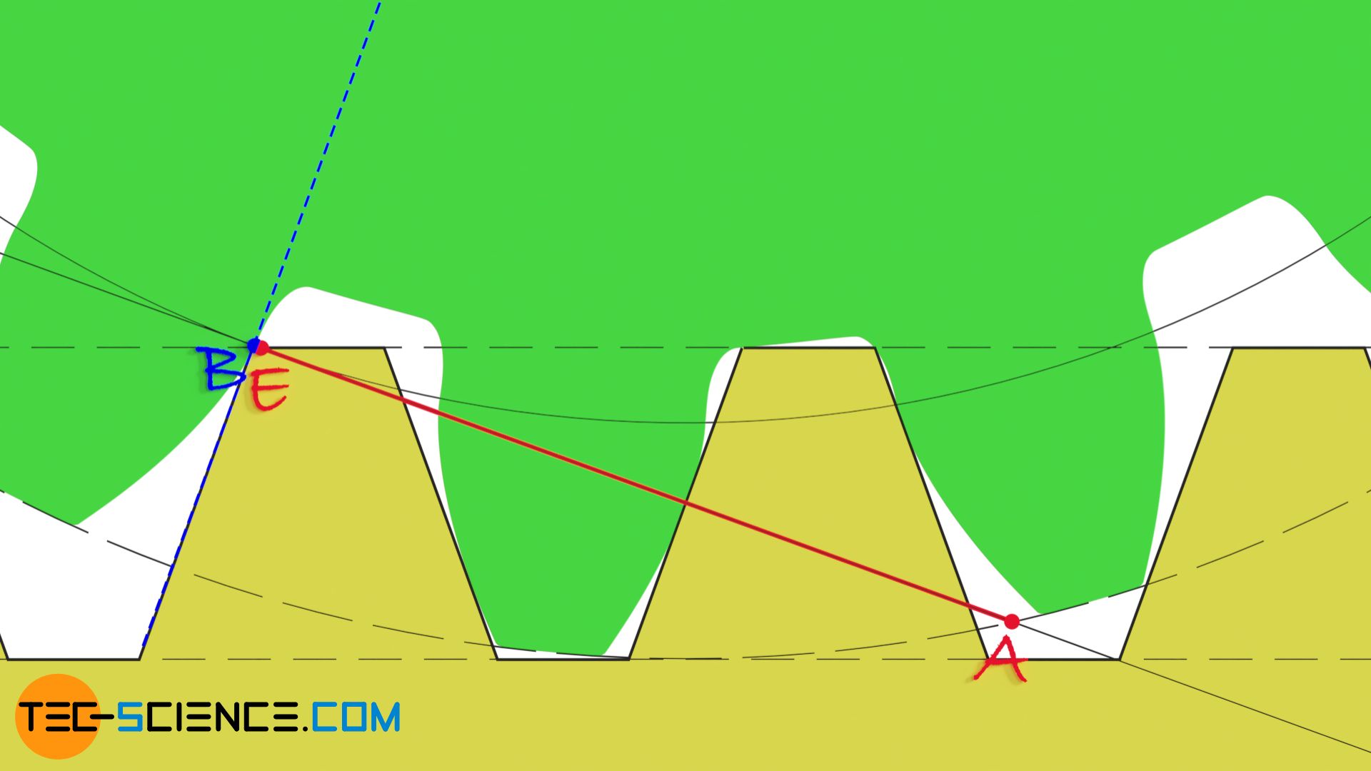
To avoid an undercut, the gear must have a minimum number of teeth. The animation below shows the reference profile of the hob as it meshes with a gear with 6 teeth. This situation can be looked at analog to the meshing of a driving rack with a gear (the basics are explained in detail in the chapter on racks). The line of action results as a tangent to the base circle and runs perpendicular to the flank of the reference profile. The meshing begins at the point of intersection A between the line of action and the tip circle of the gear and ends at the point of intersection E between the line of action and the tip line of the reference profile (the shortening of the line of contact by the undercut is not taken into account in the figure).
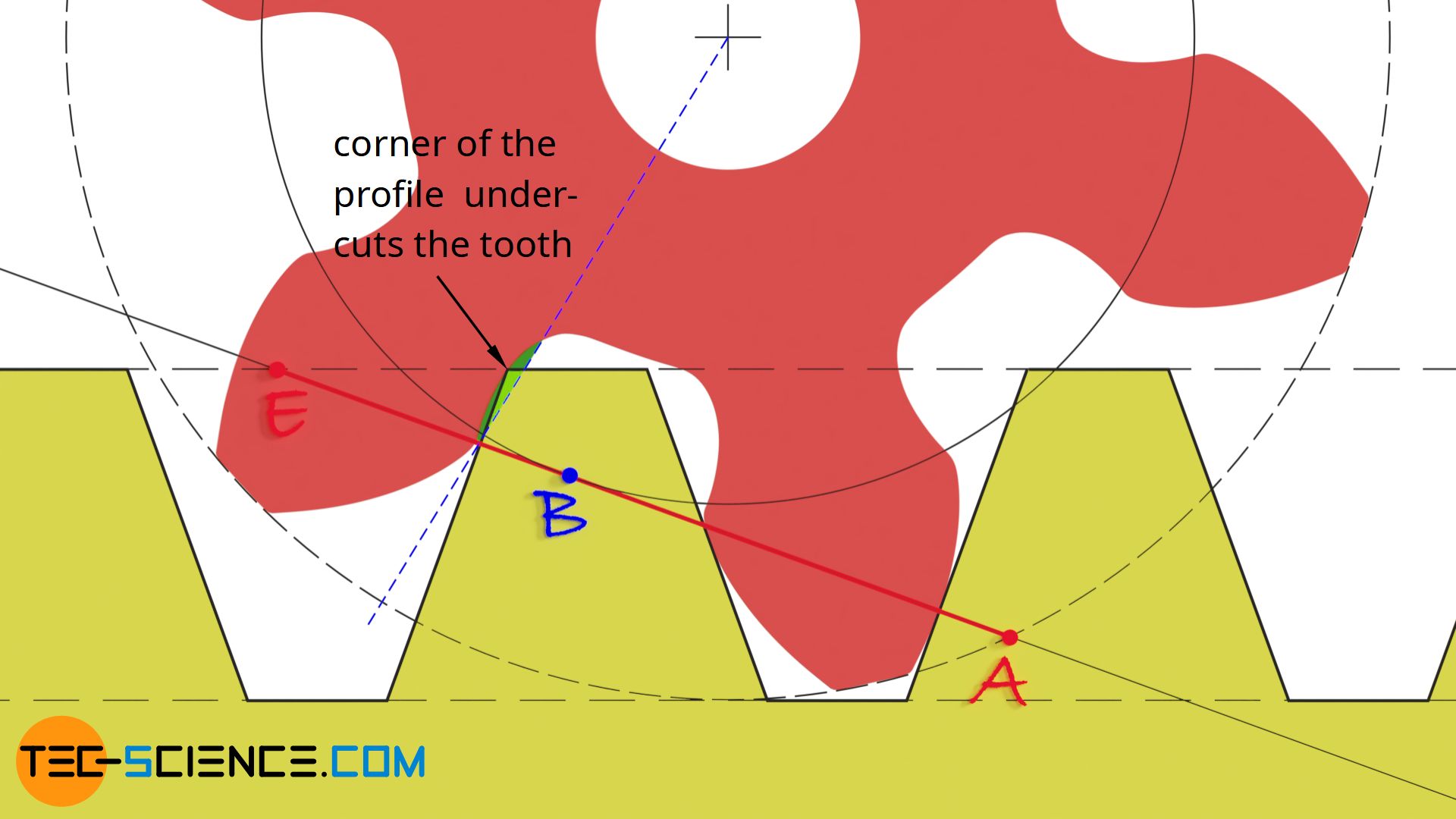
As the animation shows, the tooth is undercut from the point B. This corresponds to the point from which the corner of the reference profile moves over the radial line of the gear, thus undercutting the tooth. Between the beginning of undercutting in point B and the end of meshing in point E, the tooth is undercut within the green area.
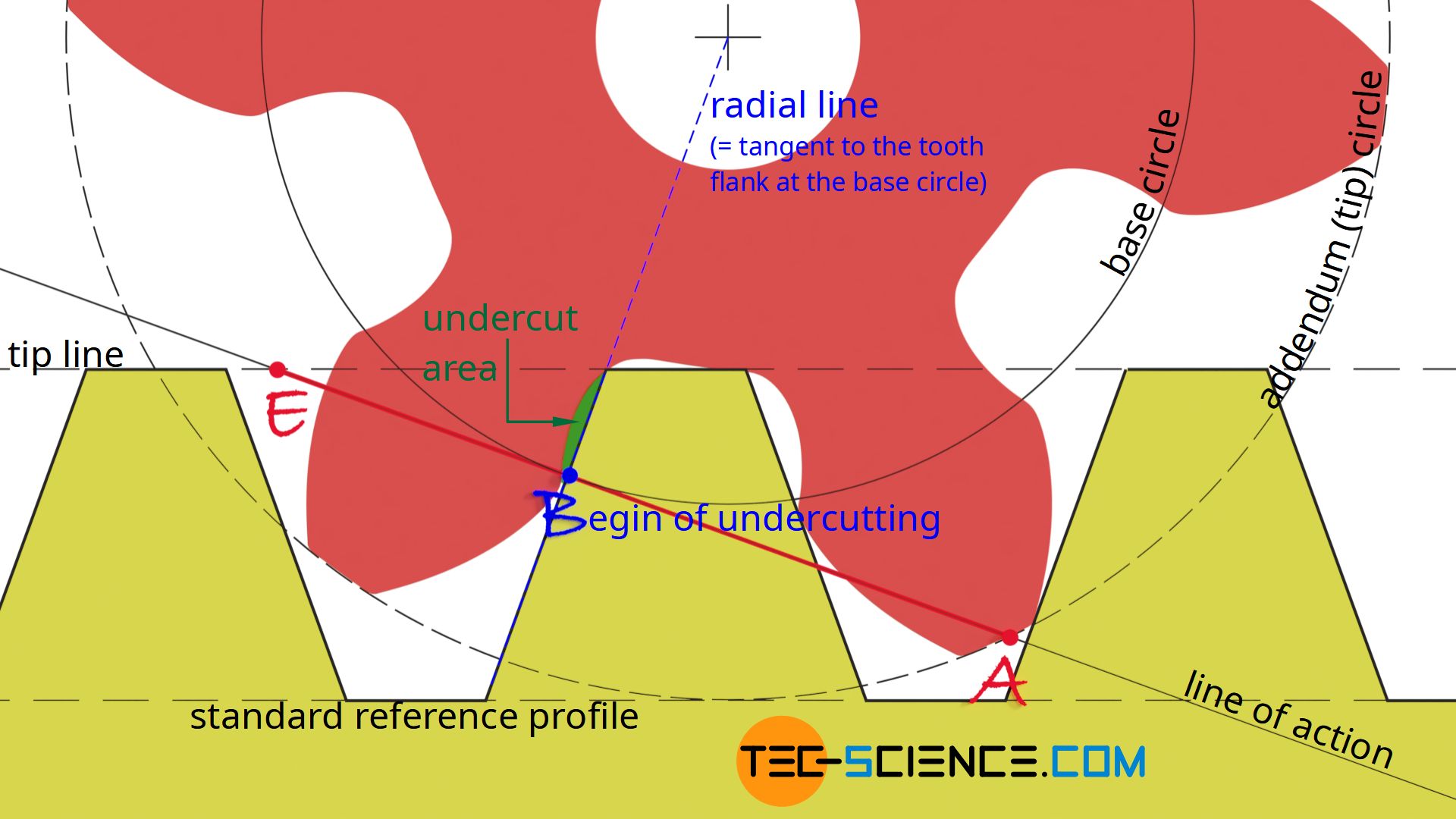
Note: The radial line corresponds to the tangent to the tooth flank at the the base circle. In the case of an undercut, however, part of the involute tooth flank is cut off, leaving a small “gap” between the radial line and the actual tooth flank.
The point B at which an undercut occurs generally corresponds to the point of contact between the base circle and the line of action. At this point, the flank of the reference profile coincides with the radial line of the gear. Beyond this point, the reference profile will then cross the radial line and undercut the tooth.
An undercut occurs at the point where the base circle touches the contact line!
In comparison to the above example, the animation below shows the meshing of the reference profile with a gear with 20 teeth. The point B at which an undercut theoretically occurs is outside the line of contact AE. The profile corner is therefore already out of mesh before it could have undercut the tooth. The teeth of the gear are therefore not undercut. An undercut will always occur if the contact point B of the base circle and the line of action lies within the line of contact AE.
An undercut always occurs when the base circle touches the line of action within the line of contact!
For the limiting case in which the teeth of a gear are not yet undercut, the beginning of the undercutting in point B coincides with the end of engagement in point E. As the animation below shows, this is the case for a gear with 17 teeth.
No undercut occurs for gears with a number of teeth above 17!
Calculation of the minimum number of teeth
The minimum number of 17 teeth mentioned in the previous section is independent of the module (or diametral pitch) and thus applies to all tooth sizes! This will be shown mathematically in the following. For this purpose, the geometric conditions resulting in the limiting case are examined more closely, i.e. if the points B and E coincide theoretically exactly.
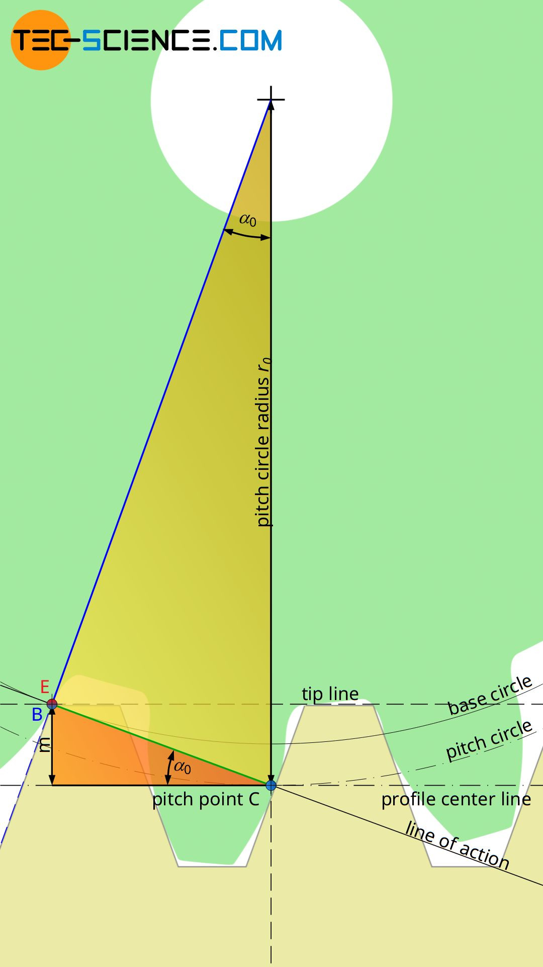
The distance between the center line and the tip line of the reference profile generally corresponds to the module m and the inclination of the flanks to the standard pressure angle α0 (see also the chapter on gear cutting). If the orange triangle shown in the figure below is considered, it can be seen that the opposite side of the standard pressure angle α0 corresponds to the module m of the gear. Thus, the following relationship applies to the distance CB.
\begin{align}
\label{1}
& \overline{CB} =\frac{m}{\sin(\alpha_0)} \\[5px]
\end{align}
The distance CB can also be determined by the pitch circle radius r0 or the pitch circle diameter d0 (see yellow triangle). The pitch circle diameter d0 results from the product of module m and (minimum) number of teeth zmin (see also the article Construction and design of involute gears):
\begin{align}
\label{2}
& \overline{CB} = r_0 \cdot sin(\alpha_0) = \frac{d_0}{2} \cdot \sin(\alpha_0) = \frac{m \cdot z_{min}}{2} \cdot \sin(\alpha_0) \\[5px]
\end{align}
The two equations (\ref{1}) and (\ref{2}) can now be equated and solved for the minimum number of teeth zmin:
\begin{align}
&\overline{CB} = \overline{CB} \\[5px]
&\frac{m}{\sin(\alpha_0)} = \frac{m \cdot z_{min}}{2} \cdot \sin(\alpha_0) \\[5px]
&\boxed{z_{min} = \frac{2}{\sin^2(\alpha_0)} } \\[5px]
\end{align}
For a standard pressure angle of α0 = 20 °, a theoretical minimum number of teeth of zmin = 17 results. In practice, however, a minimum number of teeth of 14 is assumed, at which an undercut then actually has a negative effect.
The theoretical minimum number of teeth above which no undercut occurs is 17 for a standard pressure angle of 20°. In practice, a minimum number of teeth of 14 is usually assumed!
In fact, however, it is also possible to produce gears below the minimum number of 17 teeth, without an undercut! For this, the manufacturing process must be specially adapted with a so-called profile shift. Such profile shifted gears will be discussed in more detail in the next article.

")

")

