In this article, learn more about the different types of belts and their application, as well as the respective advantages and disadvantages.
Flat belts
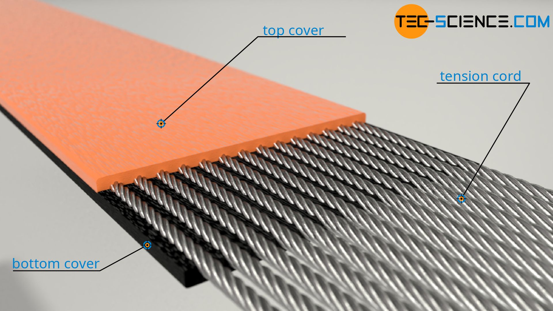
The simplest type of belt is the flat belt. It has a rectangular cross-section and was often made of leather in the early days. Today, however, steel or high-strength synthetic materials such as polyamide or aramide are used for tension cords. These force-transmitting cords are embedded in a rubber core between a top cover and a bottom cover. The bottom layer where the belt has contact with the pulley, can be coated with special rubber to increase friction and wear resistance. The top layer on the opposite side only has a protective function.
Due to their design, flat belts can in principle run on both sides around the pulleys. In this case, both sides of the belt are specially coated. The belt can then be used for multiple belt drives and for crossed belt drives.
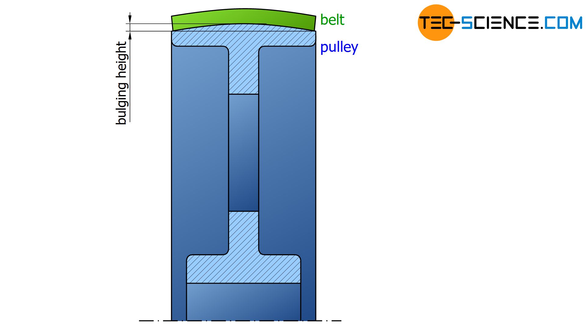
Flat belts allow high speeds and high torques to be transmitted (and thus high power). To prevent the flat belt from jumping off the pulley, the cross-section of the pulley has a slight convex crown. Depending on the width of the pulley, this hump usually ranges between 0.3 mm and 1.2 mm. This achieves self-centering of the belt and prevents it from running off and the belt keeps track.
Flat belts generally generate very little noise. This also has positive effects on the service life and the efficiency (approx. 98 %) and thus on the maintenance of the belt. Due to the relatively small belt thickness, the belt can be very strongly bent and thus allows the use with relatively small pulleys. A disadvantage of flat belts, however, is the relatively high bearing load caused by the high pretensioning forces.
Flat belts have high efficiency and flexibility as well as low wear and low noise levels; however, they require relatively high pretensioning forces!
V-belts
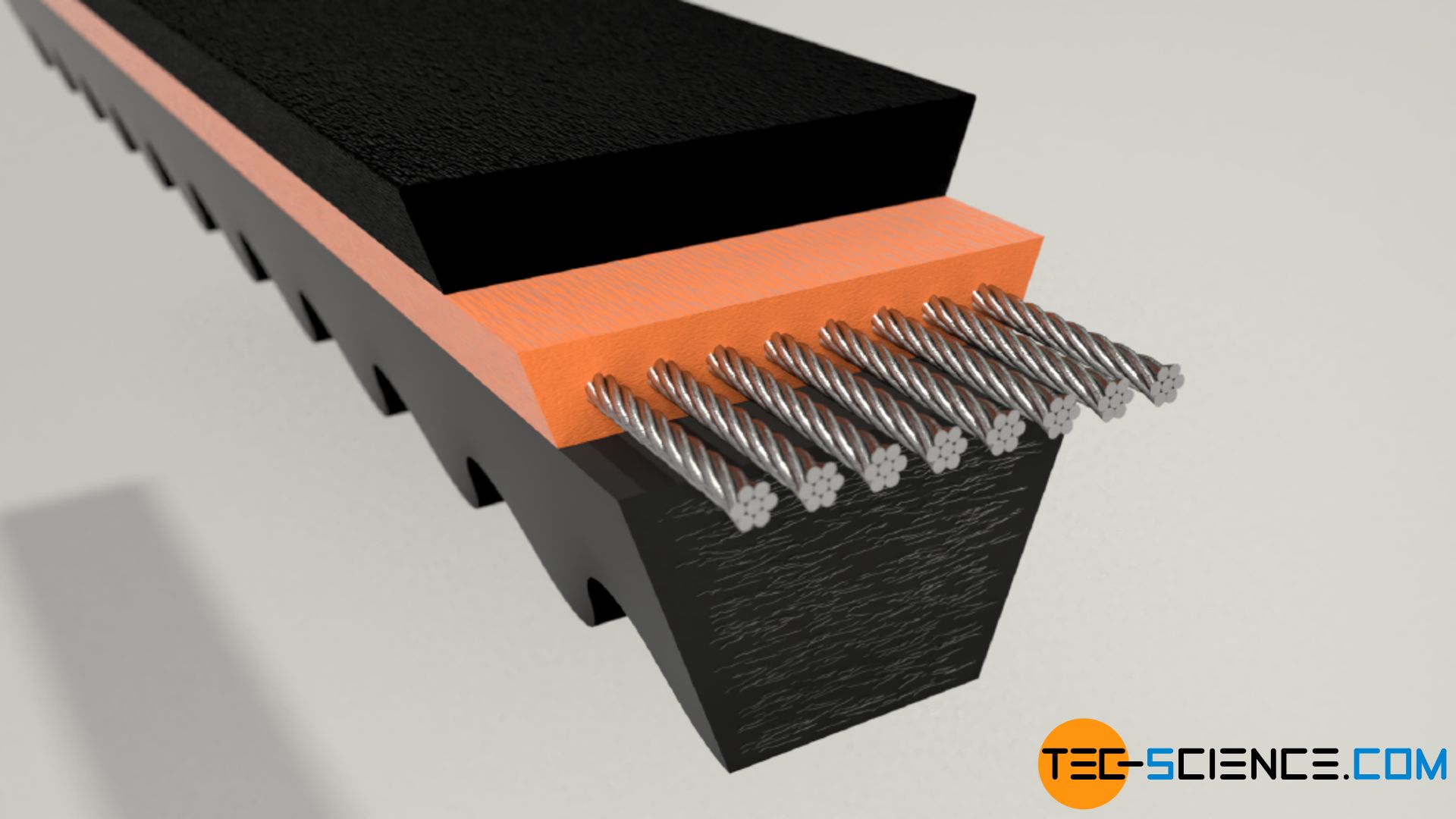
The high bearing load when using flat belts can be significantly reduced by using V-belts. The wedge-shaped cross-section leads to high frictional forces on the flanks due to the “wedge effect”. Therefore, only relatively low preload forces are necessary to generate the required frictional forces for power transmission. Accordingly, the bearing load is also significantly reduced.
Conversely, with the same pretensioning forces, much higher torques can be transmitted when using V-belts instead of flat belts. To further increase the power transmission, two or more V-belts can also be arranged parallel to each other.
V-belts can transmit significantly higher torques with the same bearing load than flat belts; however, the efficiency is lower!
The so-called groove angle \(\alpha\) is 38° or 32°, depending on the pulley diameter, whereby the belt only has contact with the pulley on the inclined flanks. The V-belt must therefore not touch the groove bottom, as the contact force must only come about by the flanks. Otherwise there would be no wedge effect! For the same radial force (bearing load), the total friction force is significantly higher for V-belts.
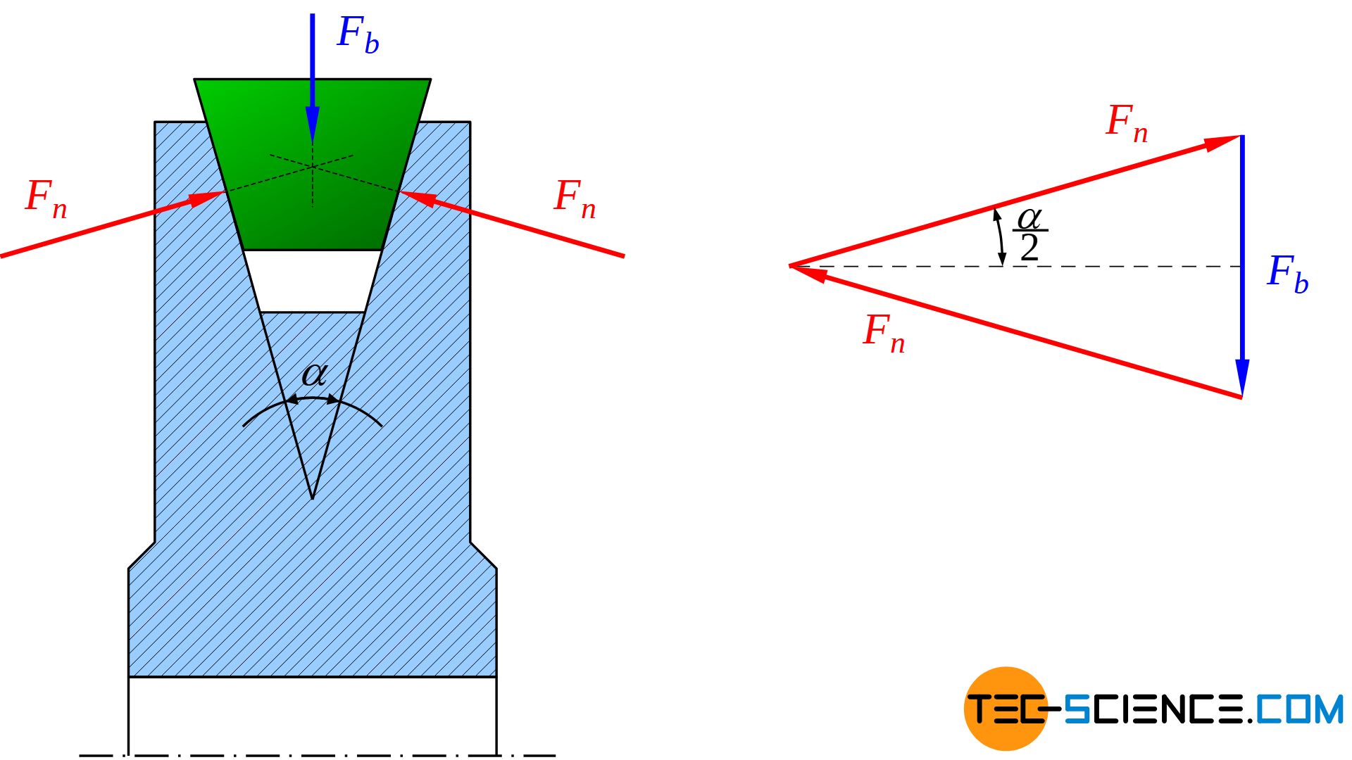
The figure above shows that the radial force \(F_b\) must be balanced with the two resulting normal forces \(F_n\) on the flanks. In this way, a relationship between the radial force and the normal forces can be established using the groove angle \(\alpha\):
\begin{align}
\sin\left(\tfrac{\alpha}{2} \right)&= \frac{\tfrac{F_b}{2}}{F_n} = \frac{F_f}{2 \cdot F_n} \\[5px]
F_n &= \frac{F_b}{2 \cdot \sin\left(\tfrac{\alpha}{2} \right)} \\[5px]
\end{align}
Since the friction force \(F_f\) is proportional to the normal force \(F_n\) according to Coulomb’s friction law, the following equation applies:
\begin{align}
F_{f} & \sim F_n \\[5px]
F_f & \sim \frac{F_b}{2 \cdot \sin\left(\tfrac{\alpha}{2} \right)} \\[5px]
\end{align}
Note, that this frictional force acts equally on both flanks, so that there is a total of twice the frictional force. The following therefore applies to the total frictional force:
\begin{align}
&F_{f,total} = 2 \cdot F_f \sim F_b \cdot \frac{1}{\sin\left(\tfrac{\alpha}{2} \right)} \\[5px]
&\boxed {F_{t,total} \sim F_b \cdot \frac{1}{\sin\left(\tfrac{\alpha}{2} \right)}} ~~~\text{valid for V-belts} \\[5px]
\end{align}
In comparison, the frictional force of flat belts is only proportional to the radial force \(F_b\):
\begin{align}
&\boxed {F_{f,total} \sim F_b } ~~~\text{valid for flat belts} \\[5px]
\end{align}
Consequently, V-belts with the same bearing load \(F_b\) can transmit higher forces by the factor \(\frac{1}{\sin\left(\frac{\alpha}{2} \right)}\) (due to the increased frictional force). Expressed in figures, a factor of 3.1 or 3.6 for groove angles of 38° or 32°.
Since the V-belts only rest on the flanks, they are specially designed for a certain range of pulley diameters as well as for certain wrap angles. Otherwise, for example, belts designed for larger pulleys would bend too much and the flanks would buckle and then no longer rest flat.
Due to the greater belt thickness of V-belts compared to flat belts, the energy required to bend the belt around the pulleys is higher. Therefore, V-belts have a slightly lower efficiency than flat belts (approx. 95 %).
While the transmission ratio for flat belts is determined by the outer diameter of the pulleys, in the cas of V-belts the so-called pulley pitch diameter must be taken as a basis for calculating the transmission ratio due to the special geometry. The pitch diameter \(d\) is defined by the nominal belt width \(b_w\). The nominal width corresponds to the belt width at the level of the neutral axis. Thus, according to the definition of the neutral axis, the nominal width always remains constant even when the belt is bent (i.e. when rotating around different pulley diameters).
It must be noted that V-belts must run in after initial assembly before they can be put into operation. This requires a correspondingly increased preload of approx. 30 % during initial operation.
Over the course of time, different types of V-belts have developed, depending on the application. The most important ones are described in more detail in the following sections.
Standard V-belts
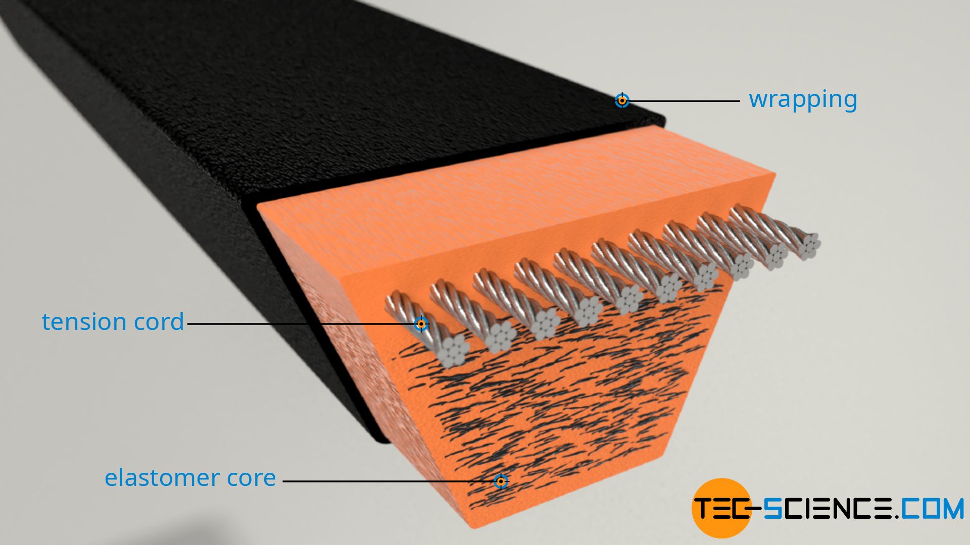
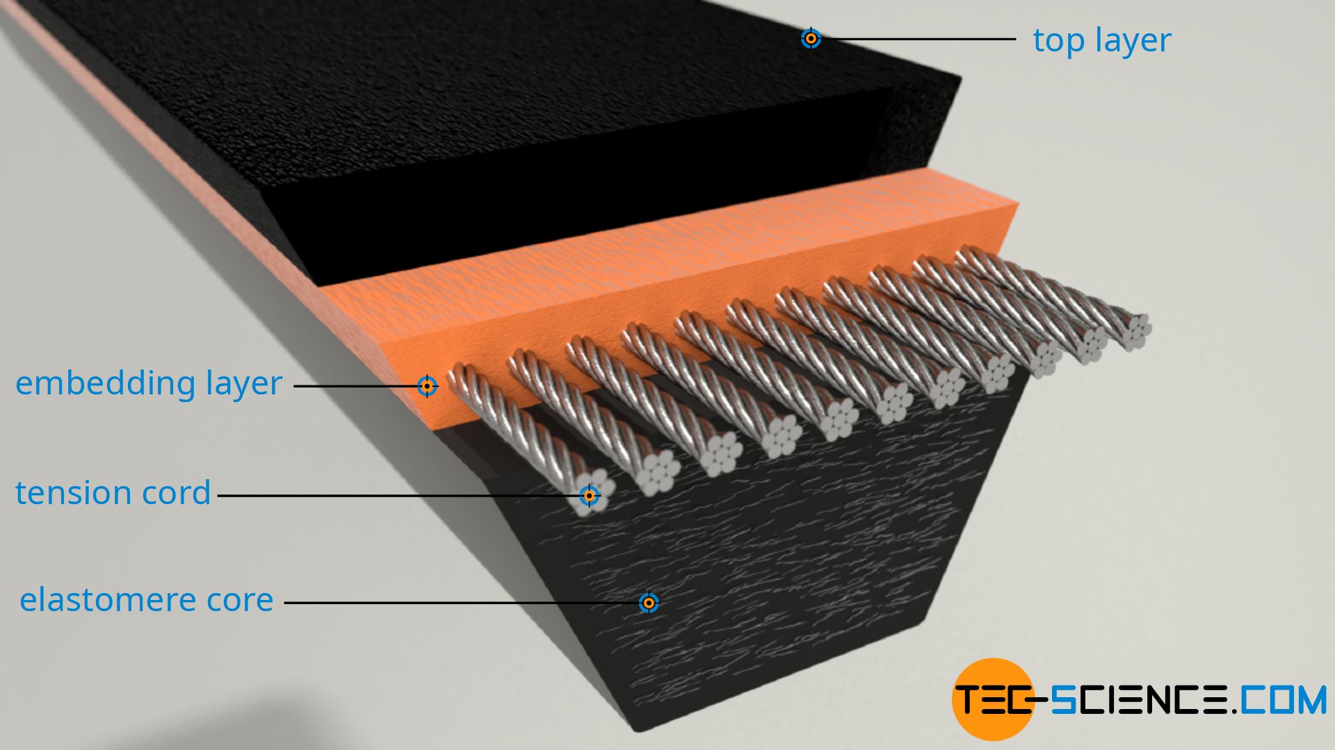
“Classical” V-belts are standardized in Germany according to DIN 2215 and have a height to width ratio of 1:1.6. Tension cords made of steel, aramid, polyester or glass are embedded in an elastomer core covered by a top layer. The tension cords run at the level of the nominal width (neutral axis).
To increase friction or wear resistance and to protect the belt from harmful external influences, the V-belt can be covered with a special rubber fabric. This is then referred to as a wrapped V-belt. Such wrapped V-belts are used, for example, in drives for pumps in the chemical industry to convey aggressive media.
Wrapped V-belts offer additional protection against harmful environmental influences!
If, on the other hand, such a rubber casing is missing, the edges of the belt are “raw”, so to speak, and one speaks of an raw edge V-belt. Due to this missing of the relatively stiff sheathing, raw edge V-belts thus have better flexibility. In addition, the force transmission from the pulley to the tension cords does not take place through the sheathing but is transmitted directly throught the core. This results in increased power transmission. To improve the transverse rigidity, elastomer fibres are incorporated transversely to the running direction of the belt.
The advantage of raw edge V-belts compared to classical V-belts is the lower wear due to the lack of wear-prone sheathing and the associated low-noise operation. In addition, the raw edges can be ground in comparison to wrapped V-belts so that belts with narrower tolerances can be produced.
Raw edge V-belts show less wear and higher efficiency than wrapped V-belts!
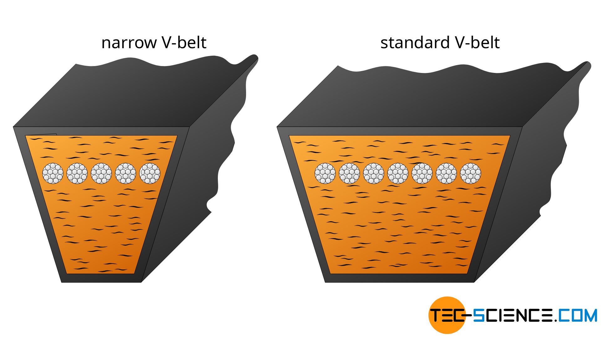
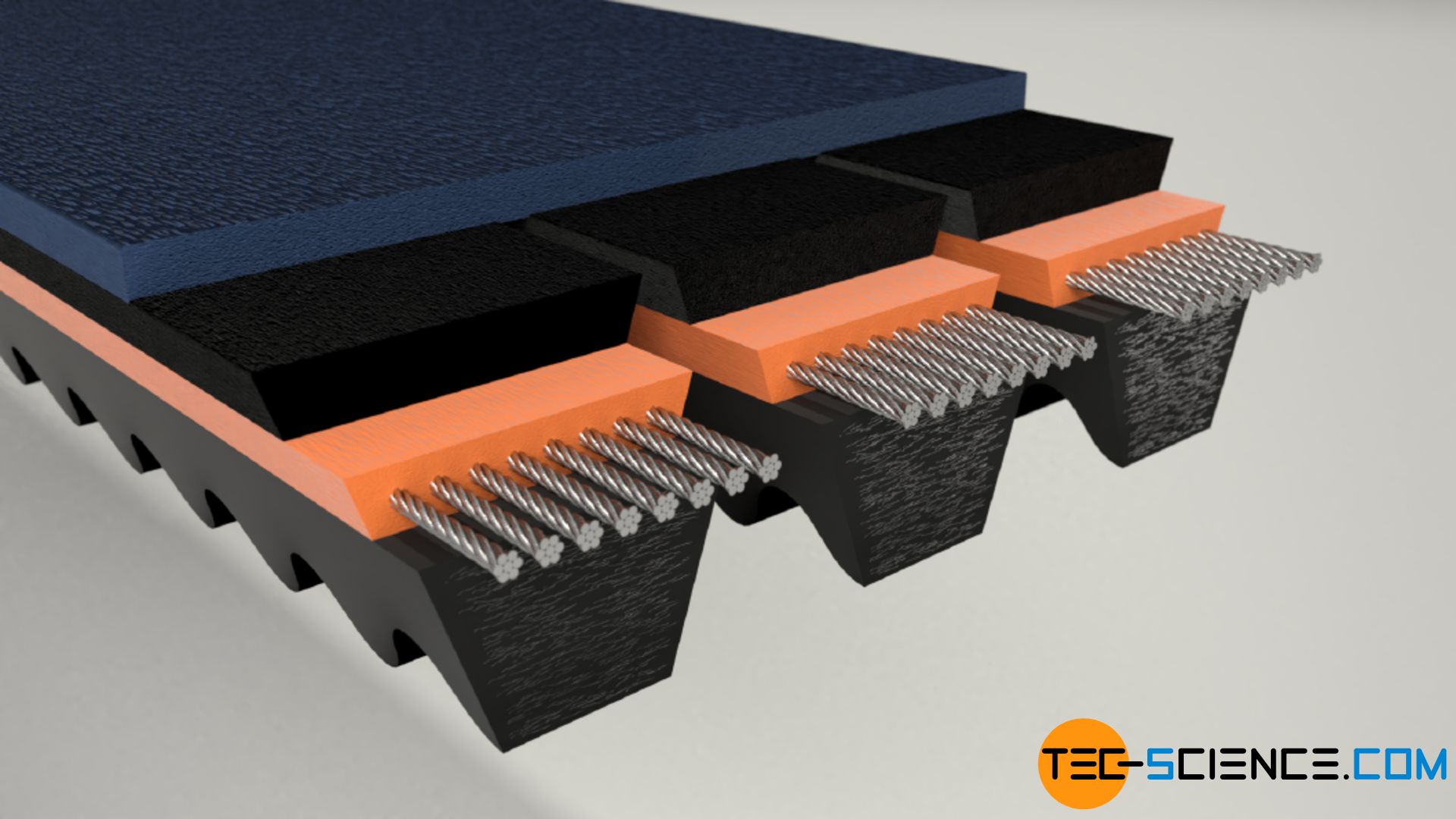
Narrow V-belts
Compared to standard V-belts, narrow V-belts have a more favourable height to width ratio of 1:1.2. The greater height (at the same width as a classic V-belt) ensures greater power transmission. Conversely, the belt width can be much smaller with the same power transmission. The associated lower belt mass of the narrow V-belt reduces the centrifugal forces occurring during operation, so that higher belt speeds can be achieved.
However, the increased belt thickness has an adverse effect on the flexibility. To compensate for this and to be able to use narrow V-belts even with relatively small pulley diameters, they are therefore cogged (so-called narrow cogged V-belts). This increases flexibility even with strong curvatures. This is why narrow V-belts are usually found in the raw edge version.
The increased power transmission combined with the high flexibility of the cogged narrow V-belts results in a relatively space-saving design of such belt drives. In addition, the lower flexural stiffness reduces the deformation energy required when the belt runs around the pulleys, which increases the efficiency compared to the classic V-belt. For this reason, classic V-belts have to give way more and more to (cogged) narrow V-belts.
Narrow V-belts offer higher transmittable powers than classic V-belts!
Wide V-belts (variable speed belts)
So-called wide V-belts with a height-width ratio of over 1:2 are used for heavy power transmissions and for applications where large speed changes occur. Therefore they are also referred to as variable speed belts.
Variable speed belts are usually cogged to reduce flexural stiffness. Such belt types are used in continuously variable transmissions in which the pulley diameter is changed by an axial shift to adjust the transmission ratio.
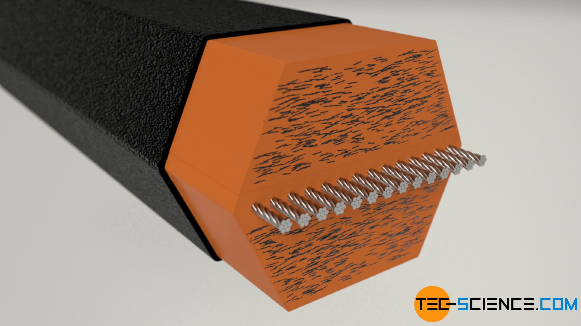
Double V-belts (hex-belts)
Double V-belts are basically two V-belts, that are put on top of each other. Both sides of the belt can therefore be used to transmit power. Due to their cross-sectional shape, double V-belts are also referred to as hex-belts. Hex-belts are able to drive two pulleys with opposite sense of rotation. The double V-belt can also be used when the direction of rotation is to be reversed.
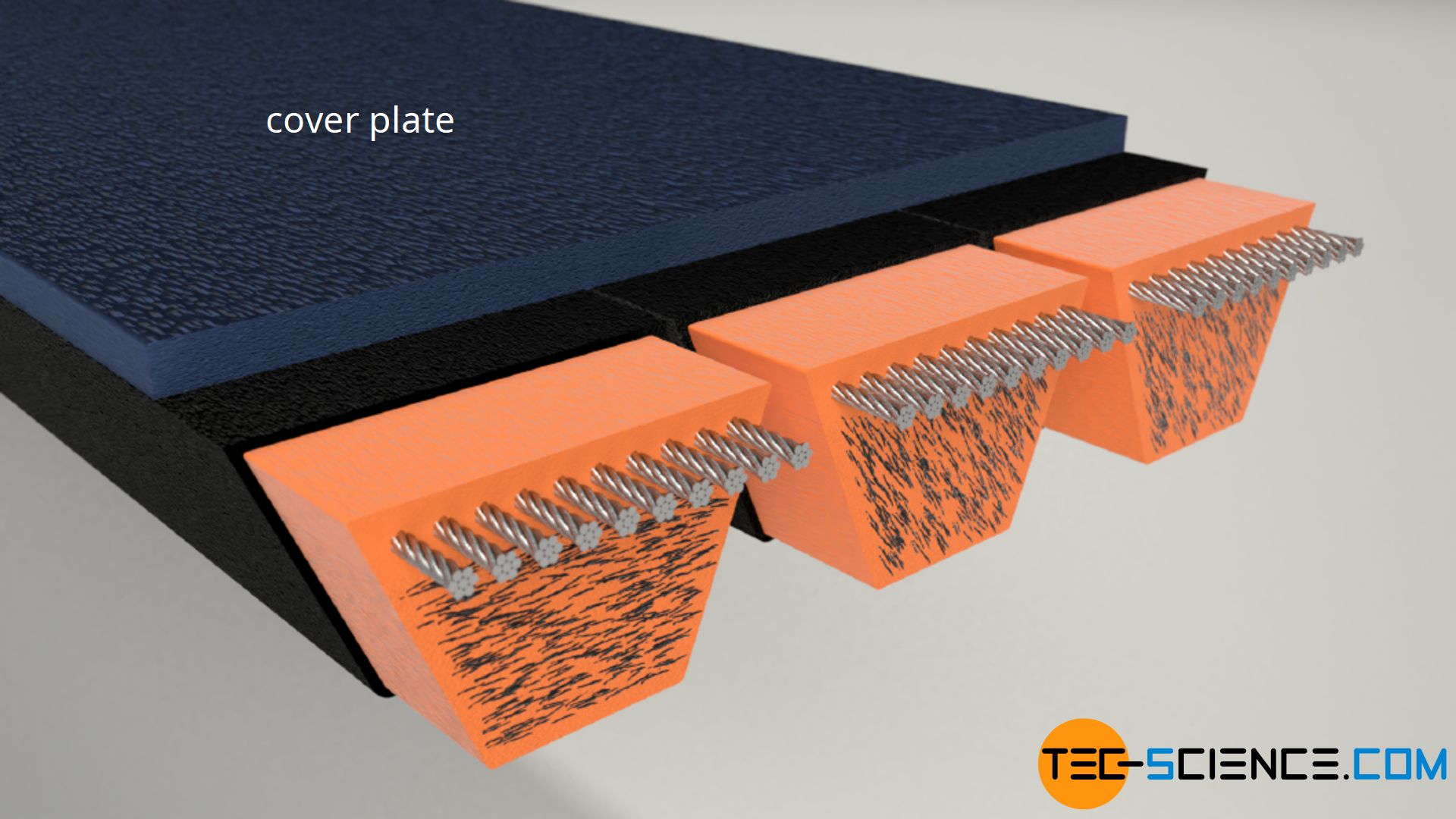
Kraftbands
If several individual V-belts are connected to each other by a cover plate, this is referred to as a kraftband (“kraft” = German word for “power” and “band” = German word for ribbon). Such a combination of several V-belts ensures, among other things, that individual V-belts do not jump off the pulley under impact loads. Kraftbands usually consist of cogged narrow V-belts in the raw edge version.
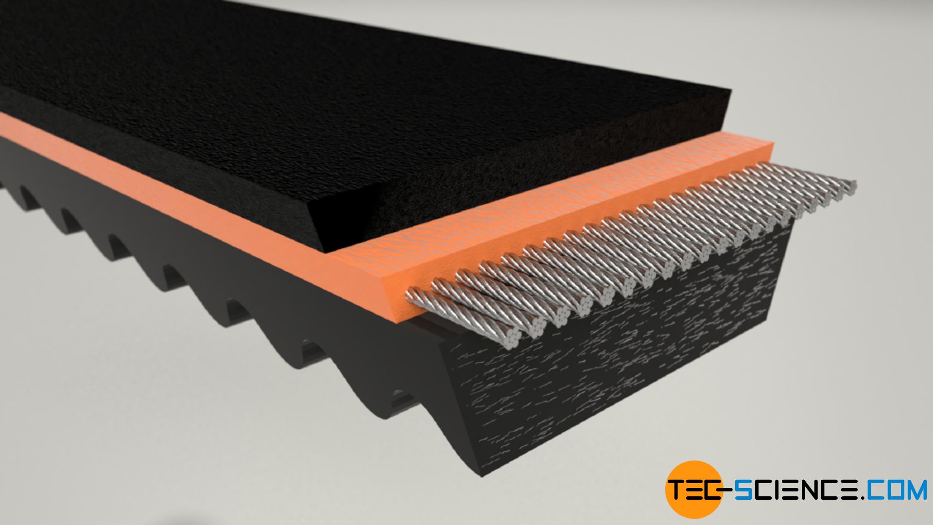
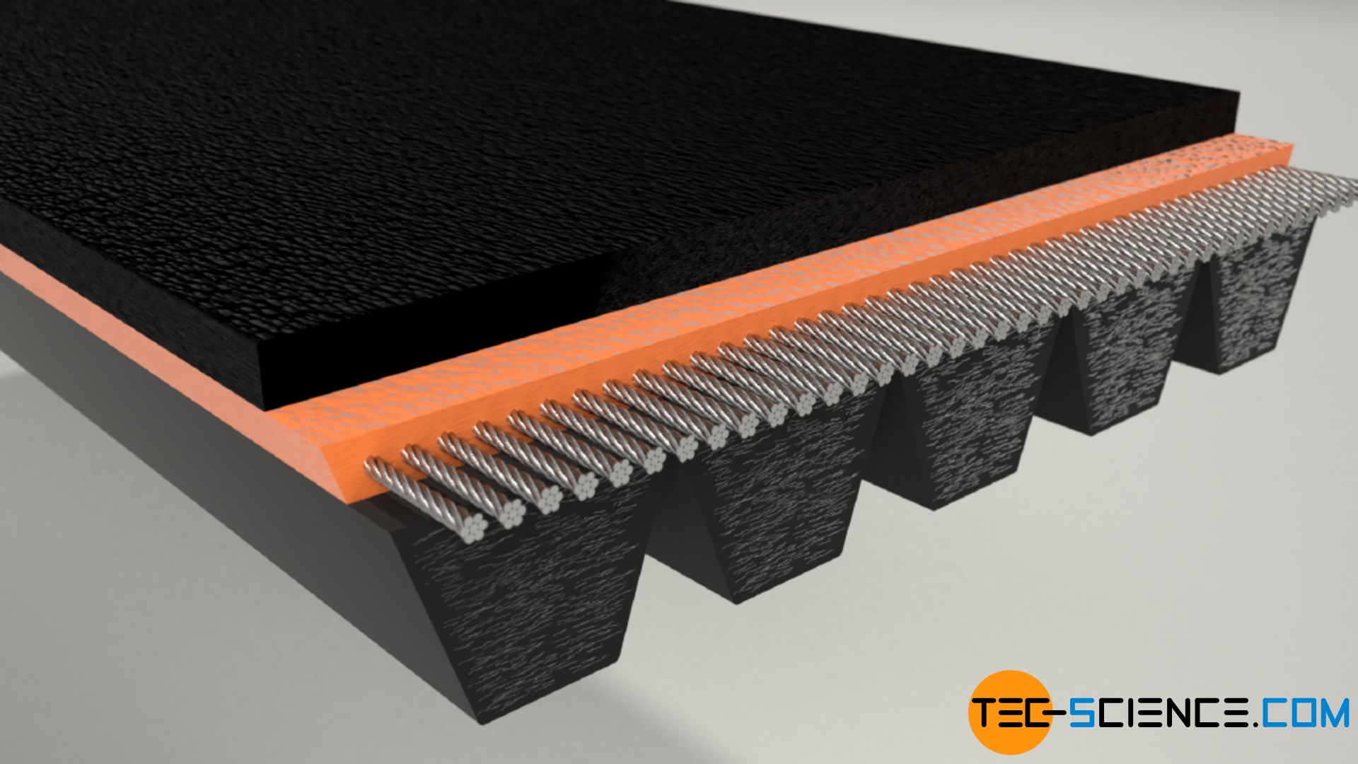
Poly V-belts (serpentine belts)
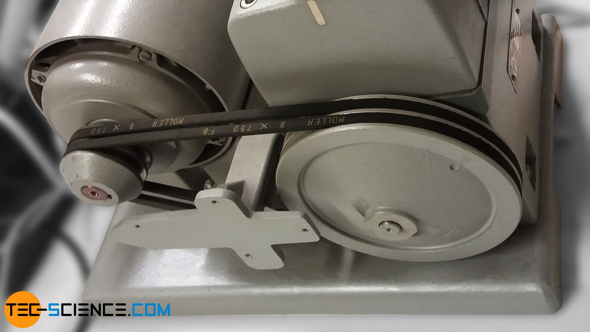
The poly V-belt (also called serpentine belt or V-ribbed belt) is a mixture of a flat belt and a V-belt, whereby the tension cords run over the entire nominal width (neutral axis) in contrast to the kraftband. Such a multible ribbed belt thus combines the advantages of both belt types to a special degree, i.e. high flexibility combined with high power transmission and relatively low bearing load. Serpentine belt are used, for example, in multiple drives in which one pulley drives several other pulley. This is the case in automobiles, for example, where the engine has to drive not only the alternator but also the pump for the servomotor, the air conditioning compressor, the fan and the water pump.
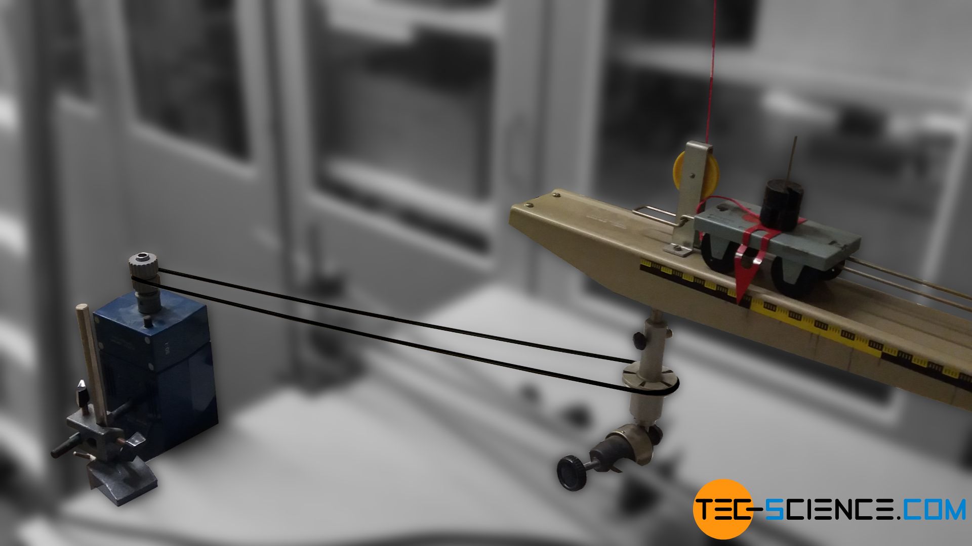
Round belts
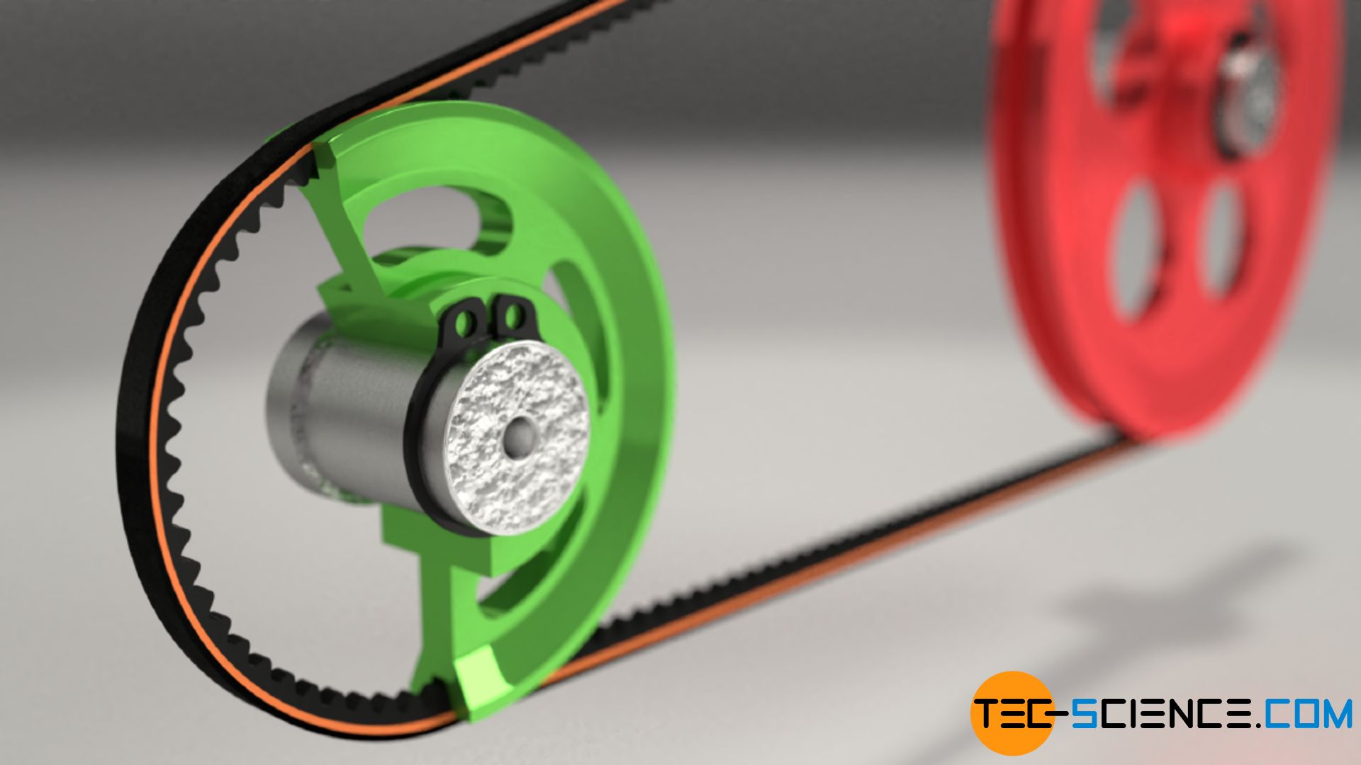
Round belts are special belts that are used almost exclusively for motion transmission and less for power transmission. Due to their symmetrical cross section, round belts can very easily be guided in different directions with the aid of guiding pulleys. The figure below shows the motion transmission of a round belt for centripetal force measurement.
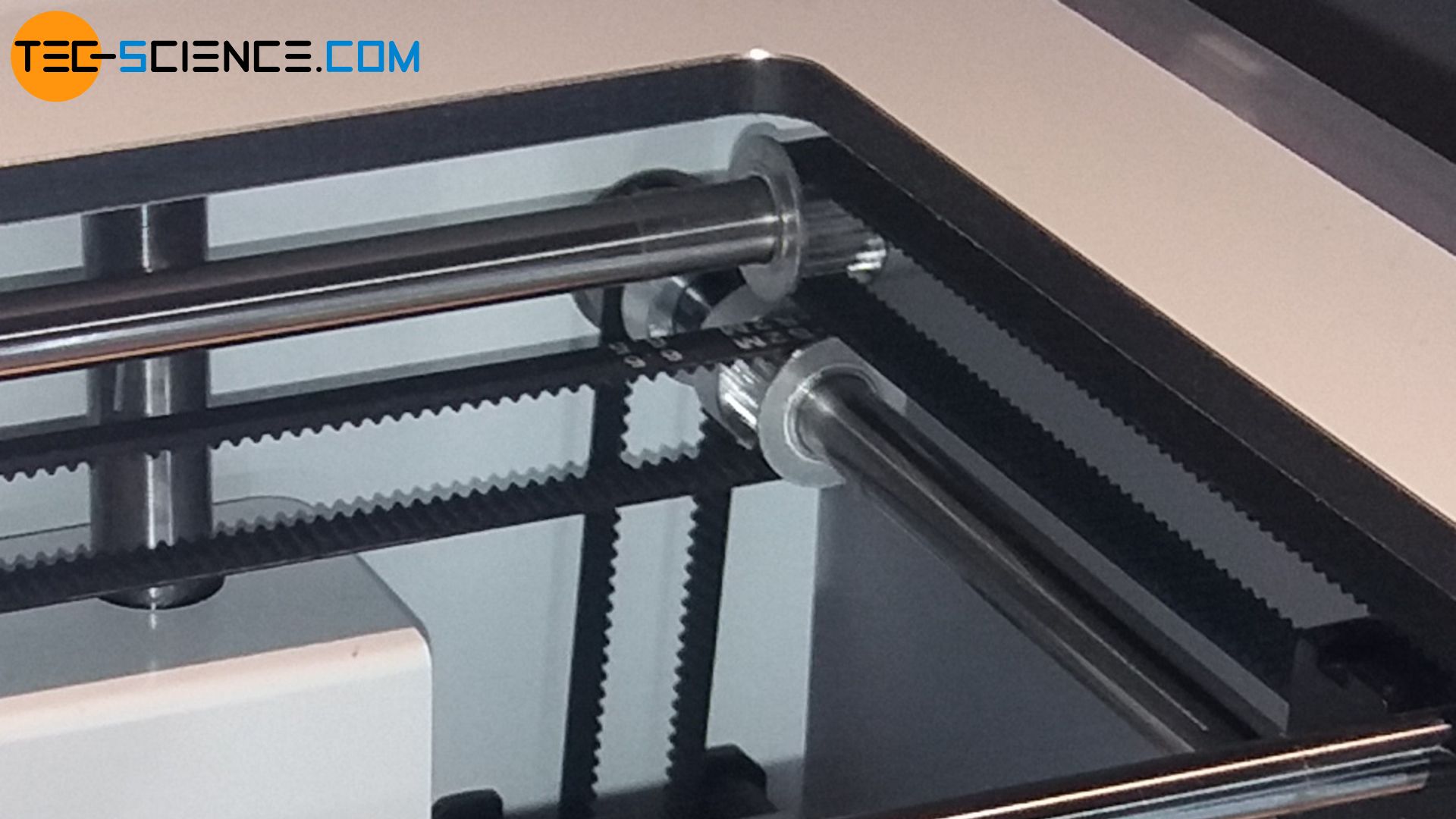
Timing belts (synchronous belts)
With friction-locking belt types such as flat belts and V-belts, slippage will occur, which reduces the efficiency and control accuracy accordingly. However, this can be prevented by toothed belts, as the teeth attached to the belt surface then transmit the force positively. Slippage cannot take place. Therefore, toothed belts are always used when precise positioning is required. For this reason toothed belts are also called timing belts or synchronous belts.

The figure below shows the timing belts used to control the printhead of a 3D printer.