The relative motion on the pulleys, which is always present due to the elasticity of the belt, is called elastic slip!
Elastic slip
When the belt rotates around the pulleys, it is exposed to different forces. Starting from the slack side force, the belt force increases at the driving pulley (by applying the circumferential force) to the value of the tight side force. Conversely, the belt force at the driven pulley decreases again from the value of the tight side force to the value of the slack side force by releasing the circumferential force (see article Maximum belt stress). Due to the elasticity of the belt, the different forces also cause different elastic strains.
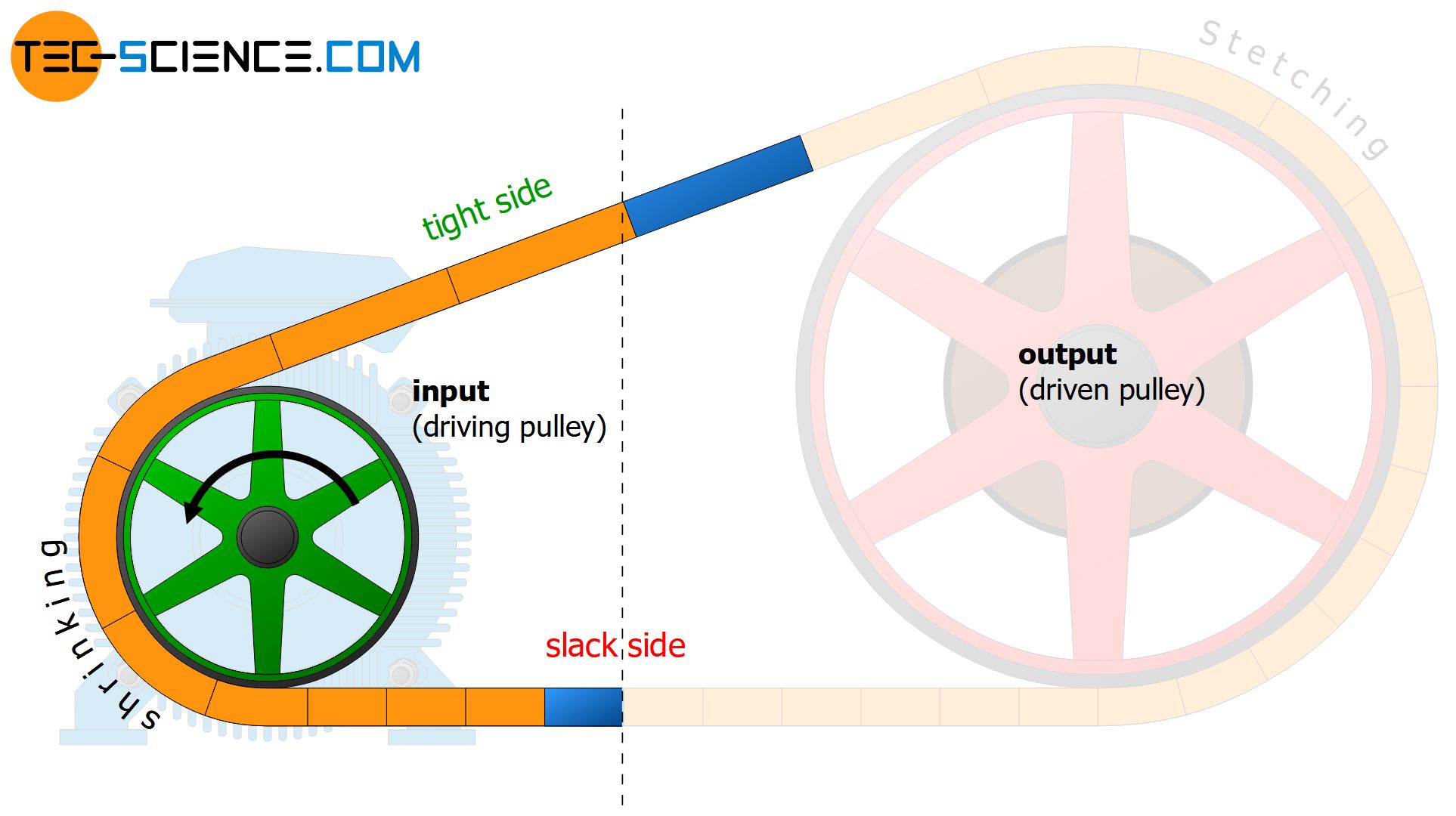
If marking lines are applied to the belt at equal distances in the load-free state, the line distances on the tight side of the belt increase due to the increased belt force during operation and decrease accordingly on the slack side due to the reduced force. The line spacings gradually adapt to the new conditions as the belt moves around the pulleys.
If a belt section between two marking lines is now looked at more closely, this section is obviously stretched on the driven pulley during rotation. The stretching belt section is pulled over the pulley, so to speak, i.e. there is relative motion between belt and pulley and thus sliding!
Conversely, the belt section coming from the tight side (and thus maximally stretched up) contracts during rotation around the driving pulley due to the decreasing belt force. The belt shrinks on the driving pulley, so to speak, and thus also results in relative motion and thus in sliding.
The belt is streched by sliding processes on the driven pulley in the direction of the tight side and contracts again on the driving pulley in the direction of the slack side!
In the animation below, additional marking lines are attached to the pulleys for better orientation. If one compares these pulley markings with the belt markings, the relative motion between belt and pulley can be seen very clearly.
Such (elastic) stretching or shrinking processes of the belt on the pulleys, which inevitably lead to relative motion, are also called elastic slip. From the belt’s point of view, elastic slip should always be kept as low as possible, otherwise enormous belt wear will occur due to the strong relative motion. The surfaces of pulleys must therefore not be too rough, as one might misleadingly assume due to the increased static friction on rough surfaces!
The relative motion on the pulleys, which is always present due to the elasticity of the belt, is called elastic slip (partial relative motion between belt and pulley)!
In addition to elastic slip, which is due to the elasticity of the belt, the belt can also slip completely over the entire driven pulley in the event of overload. This is then referred to as sliding slip. Note that every belt has a certain elasticity and therefore always results in elastic slip, whereby sliding slip should always be avoided.
Sliding slip is the complete sliding of the belt over the entire pulley in the event of overload (complete relative motion between belt and pulley)!
Belt speeds
Due to the conservation of mass (condition of continuity), the same belt mass must be moved past an imaginary point within a certain time on the tight side as well as on the slack side. Otherwise, belt mass would miraculously accumulate (or be destroyed) between the two imaginary points, since more (or less) mass is moved in over the imaginary point than is moved out again at the other point.
However, if the belt sections are now stretched on the tight side, then these sections must move faster in order to transport the same mass over the imaginary point compared to the shrunken sections on the slack side.
The belt moves faster on the tight side than on the slack side due to the greater elongation!
The belt strain and the belt speed are therefore directly related. The belt speed increases and decreases to the same extent as the belt elongation increases and decreases. The belt speed remains constant within the respective belt span, just as the forces and the elongations do. The adaptation of the different belt speeds between the slack side and the tight side takes place by stretching or shrinking processes on the pulleys.
The belt adapts to the different speeds by elastic slip on the pulleys!
Circumferential speed of the pulleys
As can be seen from the animation below, the belt is running more and more ahead due to the increasing stretching on the driven pulley. This means that the speed of an imaginary point on the belt is always slightly higher than the peripheral speed of the pulley. This corresponds to the relative motion between belt and pulley described above.
Note that the relative motion around the pulley is constantly increasing as the belt increases its speed more and more in accordance with the increasing elongation (condition of continuity!), but the pulley has a constant circumferential speed. This means that the belt speed and the peripheral speed of the pulley are only equal when the belt runs onto the driven pulley, otherwise the belt speed will be higher or the pulley speed lower.
The circumferential speed of the driven pulley is lower than the speed of the rotating belt!
Conversely, an imaginary point on the belt runs slightly behind the driving pulley due to the shrinkage of the belt (the belt is “pulled back”, so to speak, by the decreasing force). This means that the peripheral speed of the driving pulley is greater than the speed of the belt. Only when the belt runs onto the driving pulley the belt speed is equal to the peripheral speed of the pulley. Otherwise, the belt speed gradually decreases with decreasing elongation (condition of continuity!).
The circumferential speed of the driving pulley is higher than the speed of the rotating belt!
The figure below shows schematically the distribution of the speed along the belt according to the animation above.
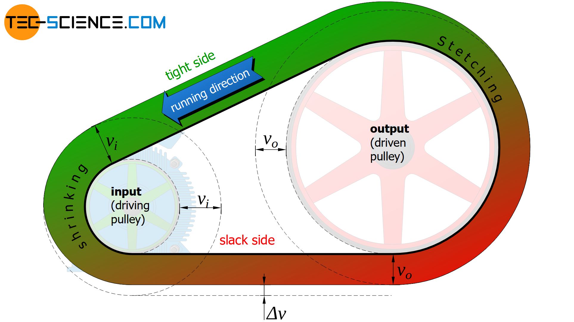
So if the driving pulley generally moves faster than the belt and the driven pulley is slower, then the circumferential speeds of the pulleys are obviously no longer identical (this would only be the case with a complete inelastic belt). This ultimately results in a loss of circumferential speed between the drive pulley (rotating faster than the belt) and the output pulley (rotating slower than the belt).
The peripheral speed of the driven pulley is lower than that of the driving pulley! The relative loss of speed in comparison to the driving pulley is a measure of the elastic slip!
The more the belt stretches, i.e. the greater the elastic slip, the greater the difference in belt speeds and thus also in the circumferential speeds of the pulleys. Therefore, the elastic slip S can be defined by the relative loss of speed at the circumference of the input pulley (vi) and the output pulley (vo):
\begin{align}
\label{def_s}
\boxed{S = \frac{\Delta v}{v_i} = \frac{v_i-v_o}{v_i} = 1-\frac{v_o}{v_i} } \\[5px]
\end{align}
Since the circumferential speeds can also be expressed by the rotational speeds n and pulley diameters d (v=π⋅d⋅n), the elastic slip can also be determined as follows:
\begin{align}
&\boxed{S = 1-\frac{n_g \cdot d_g}{n_t \cdot d_t}} \\[5px]
\end{align}
The elastic slip for belt drives (except toothed belts) is in the order of about 1 to 2 %.
Loss of power
The reduction in peripheral speed between the driving pulley and the driven pulley is directly relatet to a loss in power, because a decrease of the circumferential speed v at a transmitting circumferential force Fc means a direct decrease in power according to the P=Fc⋅v.
At the input pulley, the power Pi=Fc⋅vi is first transferred to the belt. The power reduced by the amount of the elastic slip (Po=Fc⋅vo) is then taken from the output pulley. The difference in power corresponds to the power loss ΔP due to the stretching and shrinking processes of the belt (related to heating of the belt!):
\begin{align}
&\Delta P = P_i – P_o = F_c \cdot v_i – F_c \cdot v_o = F_c \cdot \underbrace{(v_i-v_o)}_{=v_i \cdot S} = F_c \cdot v_i \cdot S = P_i \cdot S \\[5px]
\end{align}
Thus, the elastic slip S can also be determined by the power loss ΔP with respect to the power Pi at the input pulley:
\begin{align}
&\boxed{S = \frac{\Delta P}{P_i}} \\[5px]
\end{align}
Note that the elastic slip has no effect on the circumferential force and thus does not influence the torque conversion. After all, the circumferential force is only dependent on the difference between the tight side force and the slack side force (Fc=Ft-Fs). These belt forces apply equally to both pulleys, so that the acting circumferential forces on both pulleys are identical. The different belt forces only provide different elongations, but the acting forces are still transmitted to the same extent in the belt (after all, it makes no difference whether a mass is attached to an elastic manila rope or to a rigid steel rope – the rope forces are identical, only the manila rope stretches more).
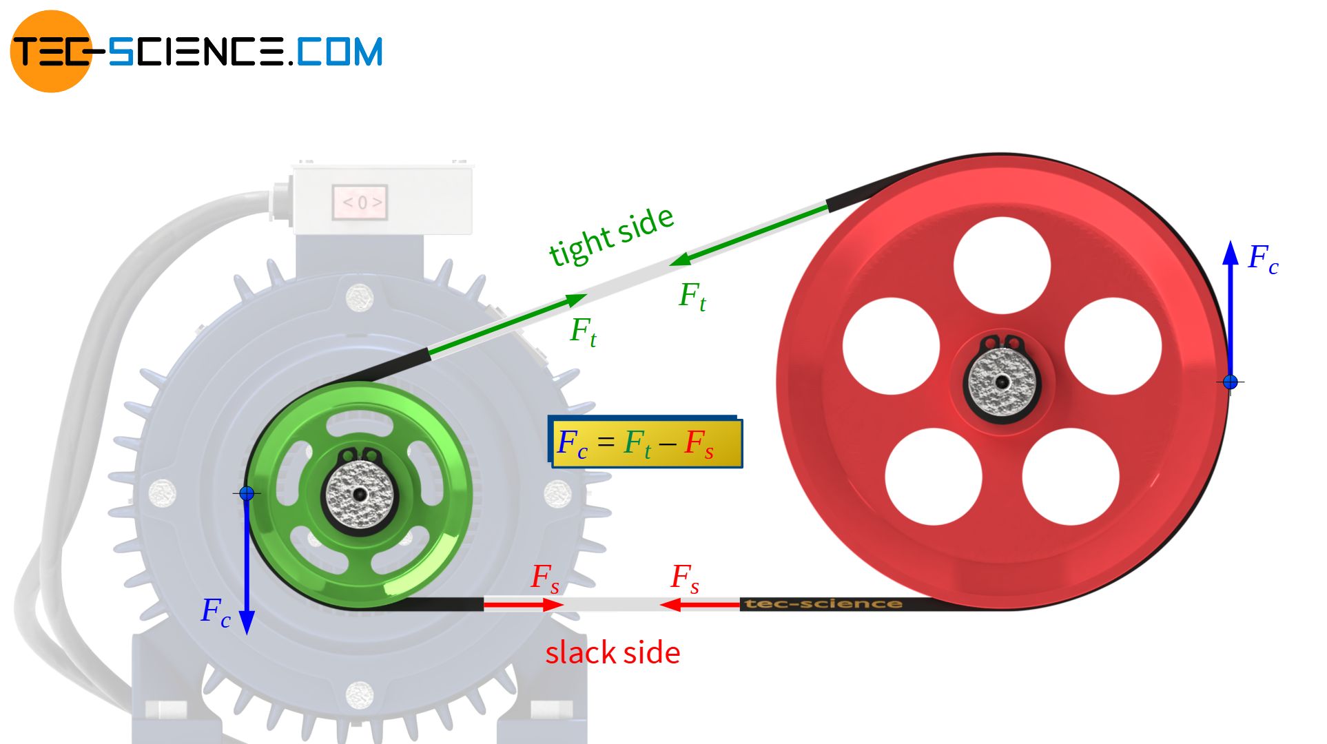
The elastic slip influences the belt speed and thus the power but not the circumferential force or the torque!
Note that the loss in power is due to the elasticity of the belt. Such elasticity is not only unavoidable but also deliberate! After all, the great advantage of belt elasticity is the associated shock absorption property at peak loads!
Sliding and adhesive areas
Due to the elasticity of the belt, slipping will always occur between belt and pulley. In such a gliding case, there is a direct relationship between the tight side force Ft and the slack side Fs according to the belt friction equation:
\begin{align}
&F_t = F_s \cdot e^{\mu_s \cdot \varphi’} \\[5px]
\end{align}
Note that in this case it is not, as previously always assumed, the static limit case in which the belt is not yet slipping. Rather, slipping is already present from the very beginning due to the elastic slip (µs as coefficient of sliding friction!).
In this sliding case, the connection between the two belt forces can be directly established by the belt friction equation. However, this also means that slipping does not generally take place over the entire wrap angle but only over the sliding angle φ’, which results from the given tight side force Ft and slack side force Fs as follows:
\begin{align}
&\frac{F_t}{F_s} = e^{\mu_s \cdot \varphi’} \\[5px]
&\ln\left(\frac{F_t}{F_s}\right) =\mu_s \cdot \varphi’ \\[5px]
\label{gleitwinkel}
&\boxed{\varphi’ = \frac{1}{\mu_s}\cdot \ln\left(\frac{F_t}{F_s}\right)} \\[5px]
\end{align}
The entire wrap area φ can therefore be divided into two zones. In the co-called sliding zone φ’ a relative motion takes place between belt and pulley. With the acting sliding friction, this zone ensures the transmission of the circumferential force. In the remaining adhesion zone, the belt adheres to the pulley without a relative motion and without force transmission.
The belt always runs onto the pulley in the adhesion zone and runs off the pulley in the sliding zone. The change of the belt force around the pulleys (from slack side to tight side and vice versa) only takes place in these sliding zones. This also applies to the belt speeds, which only change within the sliding zones.
The adhesion zones serve as a “safty zones” against slippage, so to speak, since the sliding zones can still increase at the expense of the adhesion zones and can be used for power transmission. Note that the sliding angle according to equation (\ref{gleitwinkel}) depends only on the ratio of the belt forces and these apply equally to both pulleys. This inevitably means that the adhesion zone and thus the safety against slippage will first be used up on the less wrapped pulley (usually the smaller drive pulley).
The adhesion zone serves as a safety measure against slippage and will usually be used up first on the smaller of the two pulleys!
The sliding angle φ’ relevant for power transmission can also be expressed by the circumferential force Fc to be transmitted. Thus follows with Fc=Ft-Fs or Ft=Fc+Fs:
\begin{align}
&\varphi’ = \frac{1}{\mu_s}\cdot \ln\left(\frac{F_c+F_s}{F_s}\right) \\[5px]
\label{4367}
&\boxed{\varphi’ = \frac{1}{\mu_s}\cdot \ln\left(1+\frac{F_c}{F_s}\right)} \\[5px]
\end{align}
This equation states that the sliding angle can be reduced with increasing slack side force at a given circumferential force and thus the safety against sliding slip is increased. The adjustment of the slack side tension can be carried out, for example, by tensioner pulleys.
Conversely, if the slack side tension is reduced or cannot be provided to the necessary extent, the sliding angle increases with increasing circumferential force and extends over the entire wrap angle. In this case, the entire circumferential force can still be transmitted, but a further increase in the circumferential force would then mean a relative motion over the entire wrap angle. In this case the limit of elastic slip is exceeded and sliding slip starts. The transition from the elastic slip to sliding slip is therefore always smooth.
Note: In the previous articles on belt drives, the sliding angle was equated with the wrap angle for reasons of conservative calculations. The statements made must then always be interpreted at the limit to sliding slip!
Calculation of the elastic slip
Equation (\ref{4367}) also shows that if no circumferential force is transmitted (Fc=0) there is no sliding zone (ln(1)=0!) but only an adhesion zone. With the transmission of a circumferential force, however, a sliding zone is created which increases with increasing circumferential force. As a result, the elastic slip also increases. The exact relationship between elastic slip S and circumferential force Fc to be transmitted is to be derived in the following sections.
As already explained in the section Belt speeds, the belt strains ε and the belt speeds v are directly interrelated. Mathematically this can be expressed as follows:
\begin{align}
& v \text{ ~ } (1+\epsilon) \\[5px]
\end{align}
With the definition of the elastic slip S as the ratio of speed loss Δv and circumferential speed of the input pulley vi, the following formula applies vo: circumferential speed of the output pulley):
\begin{align}
&S = \frac{\Delta v}{v_i} = \frac{v_i-v_o}{v_i} = \frac{v_t-v_s}{v_t} = \frac{(1+\epsilon_t) – (1+\epsilon_s)}{1+\epsilon_t} = \frac{\epsilon_t-\epsilon_s}{1+\epsilon_t} \\[5px]
\end{align}
Note that the peripheral speed of the driven pulley vo corresponds to the belt speed vs on the slack side and the peripheral speed of the driving pulley vi corresponds to the belt speed on the tight side vt.
The strains ε can be determined as follows using the Young’s modulus E of the belt (not to be confused with the bending modulus Eb!) and the acting belt stresses σ=F/A (with A as cross-sectional area of the belt):
\begin{align}
\frac{F}{A} &= \boxed{\sigma = E \cdot \epsilon} ~~~\text{Hooke’s law} \\[5px]
\epsilon &= \frac{F}{E\cdot A} \\[5px]
\end{align}
Finally, the elastic slip is calculated on the basis of the belt forces as follows:
\begin{align}
&S = \frac{\epsilon_t-\epsilon_s}{1+\epsilon_t} = \frac{\frac{F_t}{E \cdot A}-\frac{F_s}{E\cdot A}}{1+\frac{F_t}{E\cdot A}} = \frac{F_t-F_s}{E \cdot A+F_t} \\[5px]
\end{align}
The difference in the belt forces corresponds to the circumferential force to be transmitted (Ft-Fs=Fc). Furthermore, the value of the term E⋅A is generally much higher than the tight side force Ft. For example, the Young’s modulus of flat belts is around E = 1000 N/mm² and the permissible belt tension is around σper=10 N/mm². The tight side force in the order of ~σper⋅A will therefore be significantly lower than the value of the term E⋅A. The tight side force Ft can therefore be neglected compared to the term E⋅A, so that for the elastic slip applies in a very good approximation:
\begin{align}
\label{dehnschlupf}
&S = \frac{F_c}{A \cdot E + F_t} \approx \frac{F_c}{A \cdot E} \\[5px]
&\boxed{S \approx \frac{F_c}{A \cdot E}} \\[5px]
\end{align}
The higher the circumferential forces to be transmitted and the more elastic the belt is (e.g. low Young’s modulus!), the greater the elastic slip. With the increased elastic slip, the sliding zone also includes a larger portion of the wrap angle.
The higher the circumferential forces to be transmitted and the more elastic the belt is, the higher the elastic slip!
Note that the belt speed on the tight side is determined by the peripheral speed of the driving pulley and therefore does not change even when the circumferential force is increased (provided that the rotational speed of the driving pulley is kept constant). Only the belt speed on the slack side is reduced due to the increased elastic slip and the sliding zone increases at the expense of the adhesion zone.


