Deformation of metals is based on the shifting or sliding of atomic blocks. A distinction is made between elastic and plastic deformation.
Introduction
The relatively good deformability of metals (also referred to as ductility) compared to other materials is a significant feature. The reason for this lies in the special metallic bond. The good formability is the basis for many manufacturing processes such as bending, deep drawing, forging, etc.
Not every metal can be deformed equally well. The different degrees of ductility can be attributed mainly to the different lattice structures. In order to understand this, basic knowledge about the atomic processes during deformation is necessary.
In principle, a distinction can be made between elastic deformation and plastic deformation.
Elastic deformation
One speaks of an elastic deformation when only a relatively low force ist action on the atoms in the respective material and therefore the atoms are only moved slightly. After removing the force, the atoms regain their initial positions. The deformed workpiece recovers completely back to its original shape after the elastic deformation.
Elastic deformation is a non-permanent deformation. The deformed material returns to its original shape after the force has been removed!
Mechanically loaded components in machines (e.g. cylinder head bolts in engines) should only be subjected to elastic deformations in order not to be permanently deformed.
Plastic deformation
In contrast to the elastic deformation, the applied force during a plastic deformation is relatively large. This leads to a sliding of individual atomic planes. The resulting atomic shifts are retained after removal of the force. The individual atomic planes no longer return to their original positions but have moved on by one or more atomic distances. The workpiece remains permanently deformed after removing the force.
A plastic deformation is a permanent deformation. The deformed material does not return to its original shape after the force has been removed!
In some manufacturing processes (e.g. forging, bending or deep drawing) such a plastic deformation is desired by means of which the corresponding components permanently obtain their desired shape.
Note that with every plastic deformation, the material is always elastically deformed to a certain extent (see animation above). Thus, the material springs back a little after removing the force, even at a plastic deformation. This is also called springback.
Springback refers to the elastic portion which a deformed material recovers when the force is removed!
Such springback must be taken into account, for example, during bending. This makes it necessary to bend the component beyond the desired bending angle in order to compensate the springback.
Slip system
The atomic planes at which the atomic blocks shear during the plastic deformation are also called slip planes. After the atomic blocks have emerged from the material by one or more atomic distances, they are visible under a microscope as slip steps.
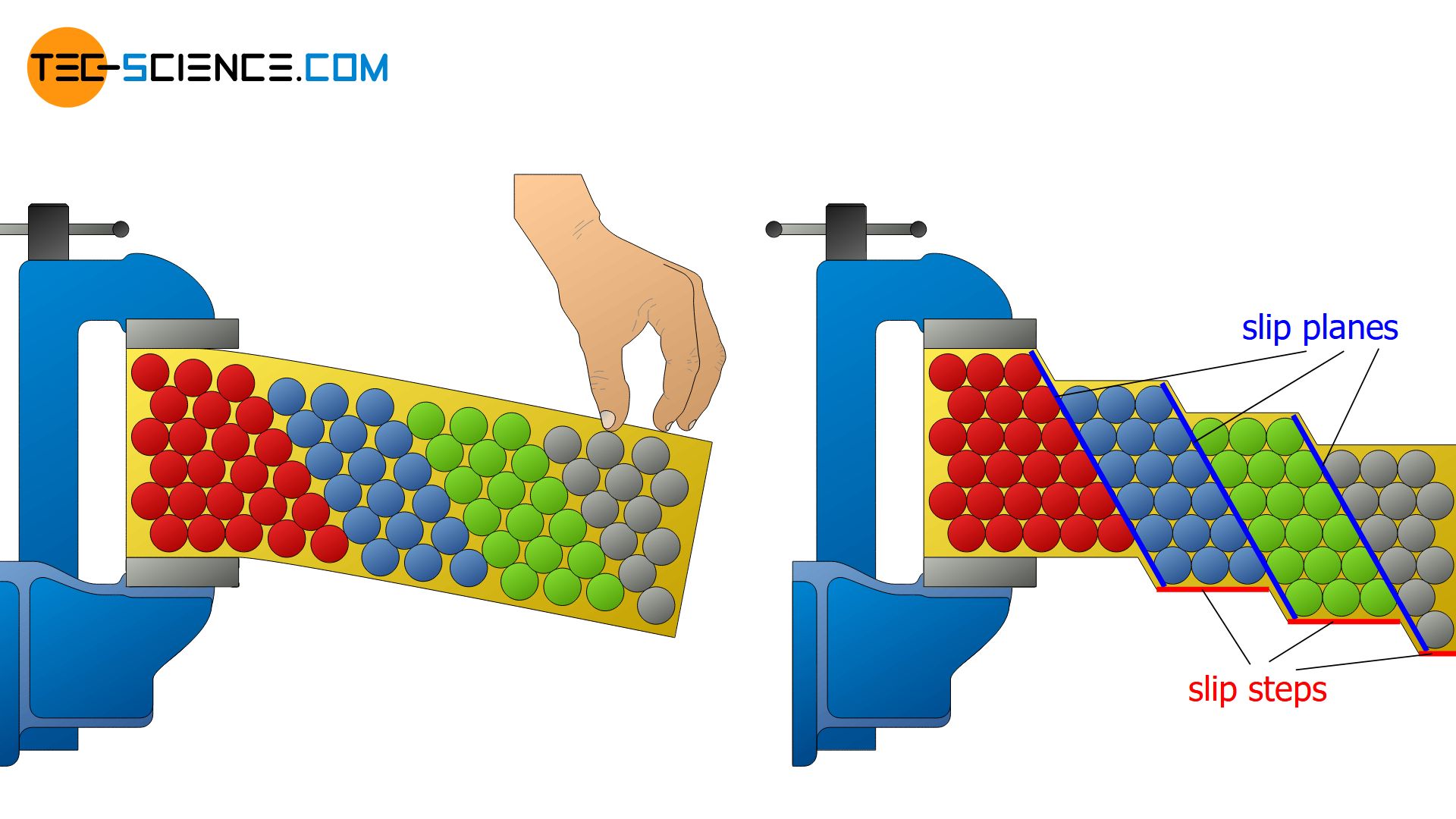
Since the reflection behavior changes with the formation of the slip steps, this manifests in a matting of the surface. This is the reason why the bending point of polished pipes often appears dull.
Note that ultimately any plastic deformation process, regardless of the type of stress (whether tensile, compressive, bending, torsional or shear stress) can be attributed to gliding of atomic blocks. Due to the strong electrostatic forces between the individual atoms and the associated stability, however, the shape of the unit cell does not change (permanently) during the deformation processes!
The cause of plastic deformation is the shearing off of atomic blocks on slip planes!
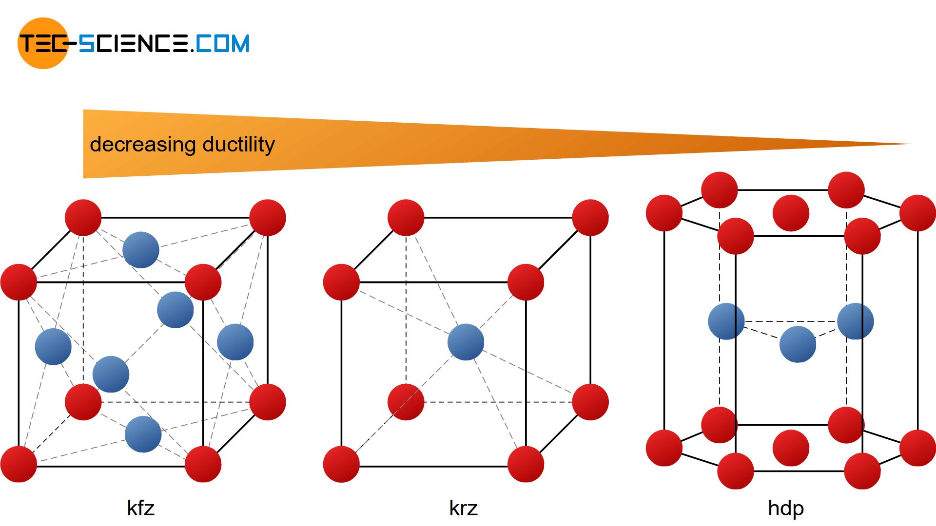
A metal is well deformable, if there are many slip planes with as many different directions of sliding as possible. This means that a deformation process can take place in many directions at the same time, without rupturing the atomic structure irreparably. The combination of slip plane and slip direction is also referred to as a slip system. For high ductility a lattice structure should therefore have as many slip systems as possible.
A slip system is a combination of a slip plane and a slip direction. The more slip systems a lattice structure has, the more deformable is the respective metal.
The different types of lattice structures, such as face-centered cubic, body-centered cubic and hexagonal closest packed, each have different numbers of slip systems. This is primarily the cause of the different deformability of the lattice structures or the corresponding metals.
Tension
As discussed in the previous section, metal deformation processes are based on slipping of atomic planes. This is only possible if a force acts in a proper way. A mere “squeezing” of the atomic structure would only cause the atomic blocks to compress (normal strain).
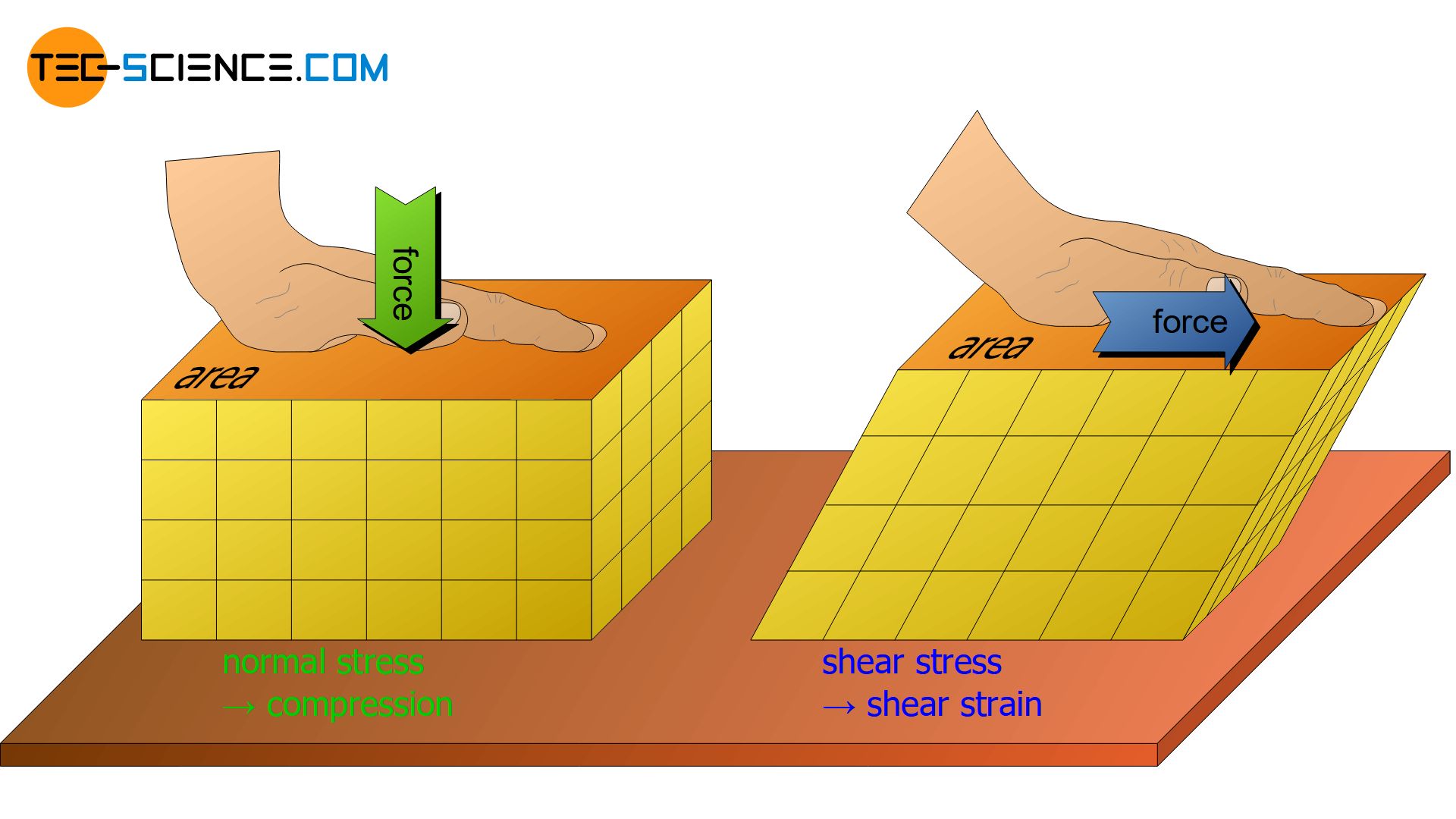
Slipping will only happen if the force acts in such a way that a lateral “shift” of the atomic structure occurs (shear strain). It is therefore useful to divide forces according to their direction of action on surfaces. Forces acting perpendicular to surfaces or a cross section are referred to as normal forces (normal forces can in principle be further divided into tensile forces and compressive forces). Forces acting parallel to a surface or a cross section are called shear forces.
Only shear forces which are directed parallel to atomic planes (shear stresses) lead to a slipping of lattice planes and thus initiate a deformation process!
Whether a force is capable of causing an atomic layer to slip does not depend solely on the force alone. In addition, of course, it is still crucial how big the atomic plane is that should be sheared off. Because the larger the surface of the atomic layer, the more “bonding points” between two atomic levels arise and must be broken up to slide off. The force per bond or the force per area is of importance!
Such area-related forces are then also referred to as stresses. For normal forces, these stresses are therefore called normal stresses. In case of shear forces the stresses are called shear stresses. The distinction between these stresses also becomes clear in the symbolism. Normal stresses are denoted by the Greek letter σ (sigma), shear stresses are given the Greek letter τ (tau):
\begin{equation}
\label{spannung}
\text{normal stress: }\boxed{\sigma=\frac{F_{\perp}}{A}} \;\;\;\;\;\; \text{shear stress: }\boxed{\tau=\frac{F_{\parallel}}{A}}
\end{equation}
Normal stress acts on a cross section and shear stress in a cross section!
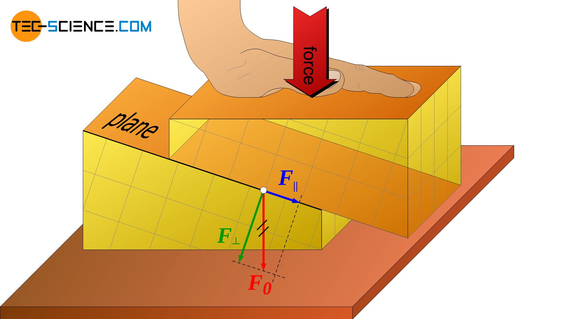
However, the fact that only shear stresses lead to a slipping of atomic planes does not mean that normal stresses acting on a material would not lead to deformation! The animation below shows that the externally applied normal stress (compressive stress) causes shear stress inside the material and atomic blocks to shear off.
By a resolution of forces, that can quickly be comprehended. The force, which has been applied from the outside, is broken down into a vertical and a parallel component regarding the slip plane. Although only normal stresses are applied from the outside, shear stresses are induced in the slip plane.
Normal stresses that are applied from the outside of a material induce shear stresses inside the material!
One must therefore always distinguish: While on a macroscopic level shear stresses as well as normal stresses can lead to deformations, the deformation process on a microscopic level can always be attributed to shear stresses.
To initiate a deformation process, a critical resolved shear stress (CRSS) must be exceeded in a slip plane (and in particular in slip direction) in order to shear off the lattice plane. Due to the binding forces between the atoms, one can make theoretical predictions what critical shear stress is necessary. For metals, the theoretical CRSS are in the range of 1000 to 3000 N/mm² (1 to 3 GPa). Theoretically, therefore, a force of 1000 to 3000 newton per square millimeter must act in a slip plane in order to shear it off.
However, in reality only a fraction of this theoretical shear stress is needed to actually deform a material! The experimental values are in a single-digit range between 1 and 30 N/mm²! In practice, the deformation already starts at much lower shear stress than calculated theoretically. The article on deformation process in real crystal structures deals with this phenomenon more closely.
Note: The word “resolved” in the term “critical resolved shear stress” means that the force which acts in the slip plane must be resolved in slip direction! The critical resolved shear stress is then calculated by this force! Only this dissolved stress, is decisive for the deformation process, since the CRSS is not only acting in the slip plane but also in slip direction! For more details see Schmid’s law.


")

