External normal stresses induce shear stresses inside a material, which become maximum at an angle of 45°.
Shear force
If a material is stressed under tension, it will eventually deform if the tensile forces F0 are too high. As explained in the article Fundamentals of deformation section, lattice planes must be slipped for this purpose.
For sliding, forces must act in a suitable manner in a slip plane, so that they can be sheared off. However, a force in the slip plane alone is not enough. Because within the slip plane, the force must also be oriented in the slip direction. If, for example, a shearing force acts in a slip plane, which, however, is oriented perpendicular to the slip direction, then the slip plane will not be easily shorn off.
Only forces in slip direction are relevant for shifting of lattice planes!
Since the combination of slip plane and slip direction forms a slip system, the following statement applies:
In order to trigger a deformation process, forces must act in a slip system!
Therefore, the question arises how the force F can be determined in a slip system according to its spatial orientation on the basis of the external force F0.
For this purpose, on the one hand, the spatial orientation of the slip plane is relevant and, on the other hand, the orientation of the slip direction within the slip plane. Both orientations are defined by an angle.
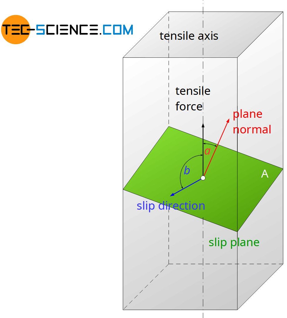
The angle \(\alpha\) describes the angle between external tensile force F0 and surface normal of the slip plane. The orientation of the slip direction is analogously defined as angle \(\beta\) between the force’s axis and the slip direction. Note that both angles are only independent within a certain range.
First, the external force F0 is broken down into a component acting in slip direction F||. This is done via the cosine of the angle \(\beta\):
\begin{equation}
\label{kraft}
F_{\parallel} = F_0 \cdot \cos(\beta)
\end{equation}
Obviously, one obtains a maximum force in the slip direction, if the force is oriented at a small angle \(\beta\). The slip plane is then inevitably very steeply inclined (large angle \(\alpha\)). With such a steep orientation of the slip plane, however, its area also increases over the cross section.
This in turn means that now significantly more atomic bonds between the lattice planes must be “sheared off”. The lattice planes to be shifted “stick” more closely together, so to speak. In this case, then even the greater force due to the disproportionately increased atomic surface (“adhesion”) is not enough to bring the plane to shearing.
So it is not the force alone one have to take into account for a sliding process but the best possible ratio of force and area (highest force per area)! It is therefore always the shear stress that has to be considered for a possible sliding process.
Shear stress
The quotient of shear force F|| (in slip direction) and slip plane surface \(A\) yields the shear stress relevant for the sliding process \(\tau\):
\begin{equation}
\label{schubspannung}
\tau=\frac{F_{\parallel}}{A}
\end{equation}
Thus, in addition to the force F|| (dependent on the angle \(\beta\)), the dependence of the slip plane surface on the angle \(\alpha \) must be known. If the cross-sectional area of the sample is denoted by A0, then the slip plane area A is given by the angle \(\alpha\) as follows:
\begin{equation}
\label{flaeche}
A=\frac{A_0}{\cos(\alpha)}
\end{equation}
If equation (\ref{flaeche}) and equation (\ref{kraft}) are used in equation (\ref{schubspannung}), then the shear stress \(\tau\) in slip direction of an arbitrarily inclined slip plane is calculated as follows:
\begin{align}
\label{a}
&\tau=\frac{F_{\parallel}}{A} = \frac{ F_0 \cdot \cos(\beta) }{ \tfrac{A_0}{\cos(\alpha)}} = \frac{F_0}{A_0}\cdot \cos(\alpha) \cdot \cos(\beta) \\[5px]
\end{align}
The expression \(\frac{F_0}{A_0}\) in equation (\ref{a}) corresponds to the externally applied normal stress \(\sigma_0\). In this way, the following relationship between the externally applied normal stress \(\sigma_0\) and the shear stress induced in a slip system \(\tau\) can finally be established:
\begin{align}
\label{s}
&\boxed {\tau = \sigma_0 \cdot \cos (\alpha) \cos (\beta)} ~~~~~ \text {Schmid’s law} \\[5px]
\end{align}
Equation (\ref{s}) is also called Schmid’s law. The geometry factor \(\cos(\alpha)\cos(\beta)\) is referred to as Schmid factor \(m\):
\begin{align}
\label{schmid-faktor}
&\boxed{\tau = \sigma_0 \cdot m} ~~~~~\text{mit}~~~~~\boxed{m=\cos(\alpha) \cos(\beta)} \\[5px]
\end{align}
The Schmid factor describes the relationship between external normal stresses and the shear stresses caused in a slip system!
Critical resolved shear stress
If a certain critical shear stress is exceeded in a slip system (slip system with the largest Schmid factor), then the lattice planes begin to shear off or dislocations begin to move. The deformation process begins.
Note that the critical shear stresses do not refer to the mere shear stress in a slip plane but to that component acting in slip direction. Therefore, these critical shear stresses are referred to as critical resolved shear stresses (shear stress resolved into the component acting in slip direction).
In order to shear off slip planes, certain critical resolved shear stresses must be exceeded in a slip system (especially in slip direction)!
The difference between the mere shear stress in a slip plane and the resolved shear stress in the slip direction will be explained by a short numerical example. For this purpose, a slip plane is considered which is inclined at an angle of \(\alpha\) = 15°.
If a normal stress of \(\sigma_0\) = 400 N/mm² is applied from the outside, then a shear stress of \(\tau_{p}\) = 100 N/mm² acts within the slip plane. Only if the slip direction were oriented at an angle of \(\beta\) = 75°, 100 N/mm² of (resolved) shear stress would also act in slip direction.
If, however, the slip direction in the slip plane is oriented at an angle of \(\beta\) = 80, then only a shear stress of \(\tau_{R}\) = 67 N/mm² will result in this slip direction. Only this shear stress, which is resolved in slip direction, is relevant for a possible slipping process!
Maximum resolved shear stress
This raises the question of how a slip system must be spatially oriented in order to obtain the greatest possible shear stress there (maximum Schmid factor). Is it perhaps even possible to orient a slip system in such a way that the entire external normal stress in the slip direction is active?
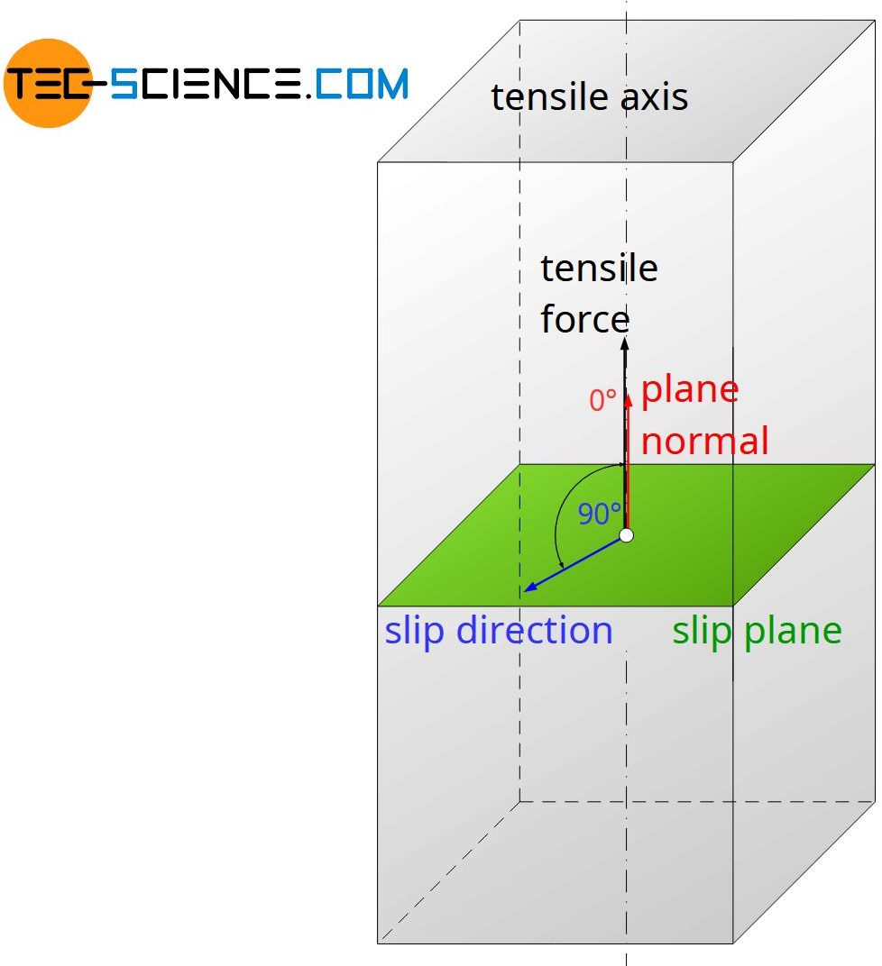
For this equation (\ref{schmid-faktor}) must be considered closer. First, the expression \(\cos(\alpha)\) reaches the maximum value 1 for \(\alpha\) = 0, but in this case \(\beta\) inevitably reaches 90° and thus \(\cos(\beta)\) = 0. The Schmid factor is thus zero. In slip planes that are aligned perpendicular to the pulling axis, therefore, no shear stress acts!
Even for the reverse extreme case, when the slip planes are aligned parallel to the tensile axis (\(\alpha\) = 90°), there is no stress in the slip plane, because then inevitably applies \(\cos(\alpha)\) = 0!
In fact, the largest shear stresses in a slip plane will be found at an angle of \(\alpha\) = 45°. The maximum resolved shear stress results when the slip direction is directed “upwards” in this 45° inclined sliding plane. The angle \(\beta\) in this case is also 45° (note that both angles can not be chosen independently). The Schmid factor reaches 0.5 in this ideal case. This corresponds to the maximum possible value of Schmid’s orientation factor:
\begin{align}
&m_{max}=\cos(45°) \cos(45°) = 0,5 \\[5px]
&\boxed{m \le 0,5} \\[5px]
\end{align}
Thus, the maximum resolved shear stresses are at most half the value of the external normal stresses.
In slip systems inclined at an angle of 45°, the greatest shear stresses occur. They amount to half of the externally applied normal stresses!
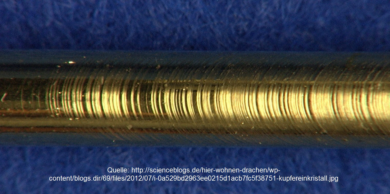
This is also the reason why special oriented single crystals in the tensile test have slip steps at an angle of 45° to the tensile axis. Further information can be found in the article deformation of single crystals again.

")


