In this article, learn more about what a siphon is and how it works in practice.
Introduction
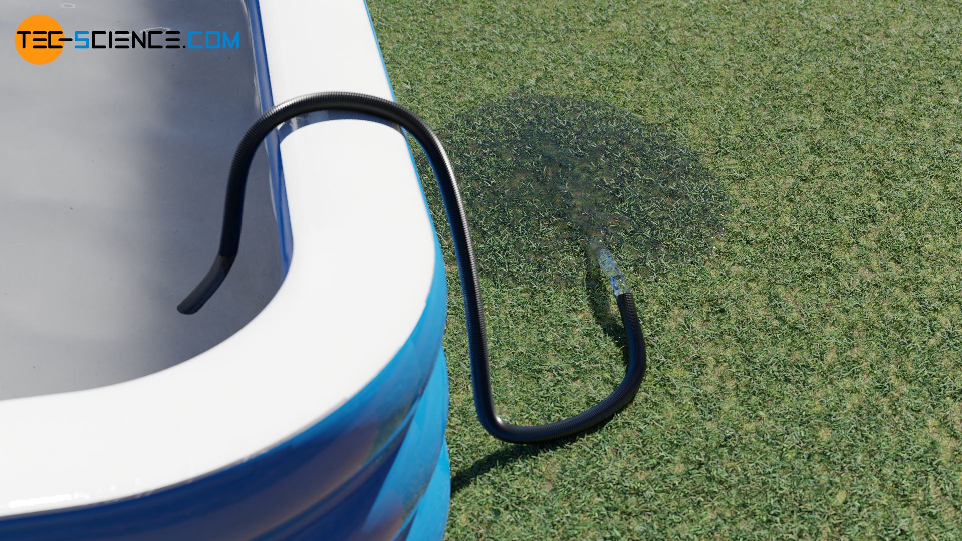
If, for example, you want to empty a pool by a garden hose, you only have to place one end of the hose over the edge into the pool and the other end outside. The outside end of the hose only has to be lower than the water level. Once the water is sucked in, it runs out of the hose permanently. As long as the lower end is always held lower than the water level, the water is also carried over larger heights, such as over the edge of the pool (to the maximum height to be overcome later more). Such an arrangement is also called a siphon or siphon spillway.
Explanation
This paradoxical behavior is due to hydrostatic pressure. In order to better understand this, a plastic bottle filled with water is first considered. A flexible tube is mounted on the screw cap of the bottle. If the bottle is now turned upside down, the water will begin to flow out through the tube. The outflow of the water leads to an increase in the volume of air inside the bottle. Since no air can inflow through the relatively small hose, a negative pressure is created inside the bottle.
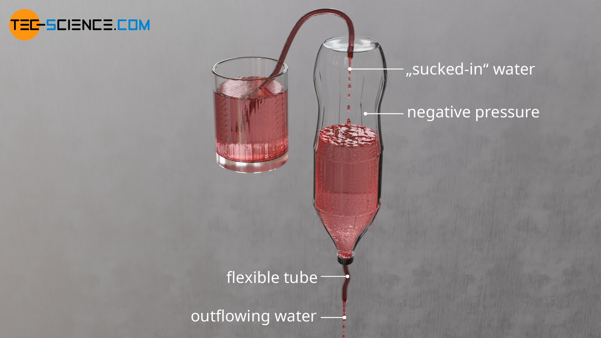
The resulting negative pressure in the bottle can then be used to suck water from another vessel. Only a second flexible tube has to be attached to the bottle from above. This tube is now placed in the vessel from which the water is to be sucked off. The water is sucked in so to speak by the negative pressure in the bottle, which is produced by the outflow of the water.
In principle, the air volume in the bottle at the beginning can be chosen arbitrarily small. And finally, even an initial air volume can be completely dispensed with. The pressure gradient required to pump the water will then form directly inside the water. The last step is to use another flexible tube instead of the bottle. Finally one obtains in this way a single tube, which sucks the water from a higher level over the apex and then drains it into a lower level.

The illustrated example with the bottle also clearly shows that the maximum height be overcome between the higher water level and the apex of the hose is limited by the maximum suction lift of about 10 meters. After all, the maximum negative pressure that can be generated is a vacuum. With an atmospheric air pressure of 1 bar, this ambient pressure can thus push a maximum water column of 10 meters upwards. The ambient pressure is therefore not sufficient for higher heights.
Mathematical derivation
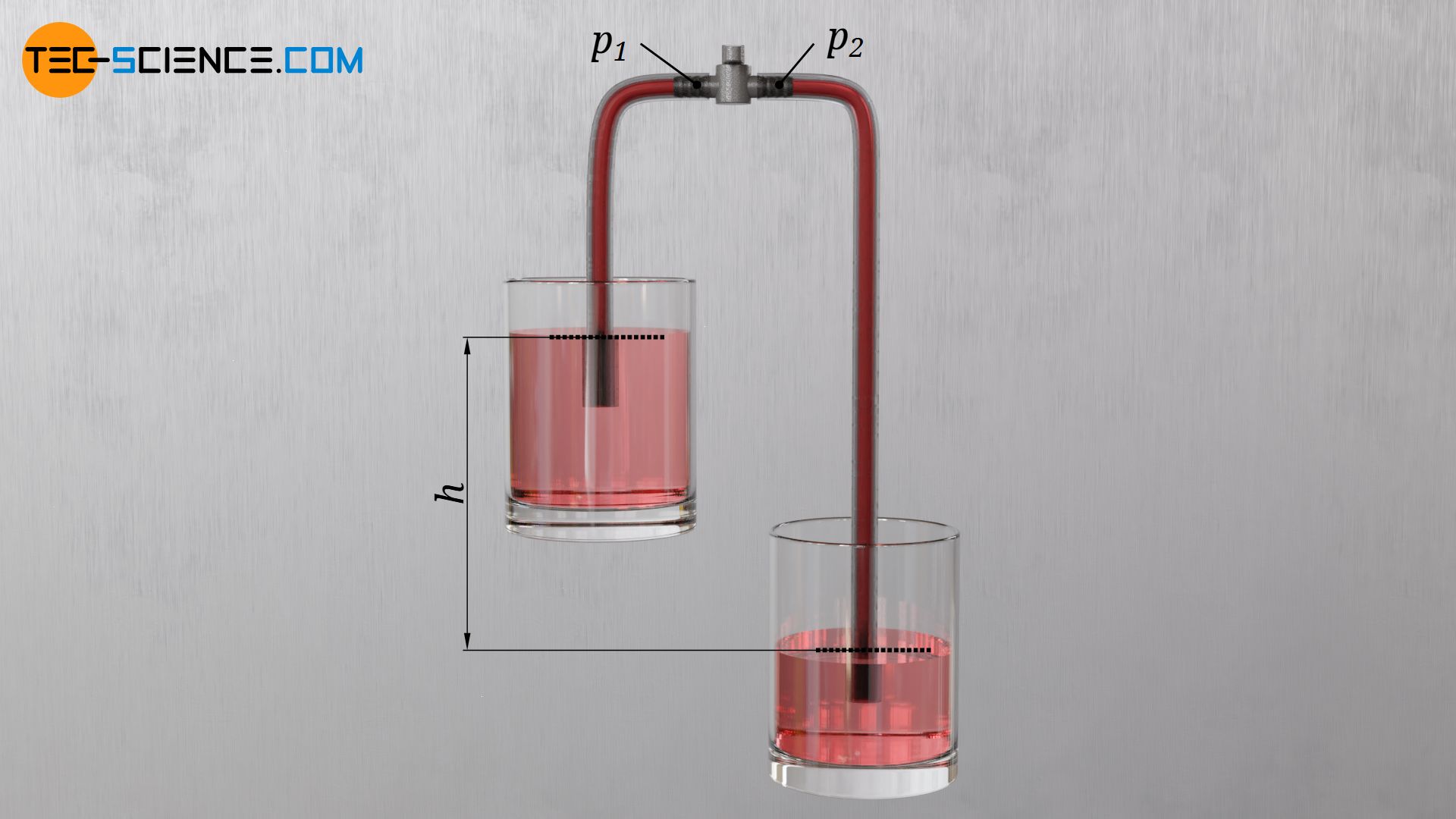
If a flexible tube is used to pump water from a higher reservoir to a lower reservoir, then only the difference in height h in the water levels is relevant for driving the water flow. To show this, a stopcock is inserted into the highest point of the water-filled tube. The stopcock is first closed. To the left and right of the valve different pressures p1 and p2 will be formed. The negative pressure at these points causes the greater ambient pressure p0, which acts on the water surface, to push water upwards in the respective tube sections according to the drinking straw principle. In this state, the respective water columns remain in position in the tube sections.
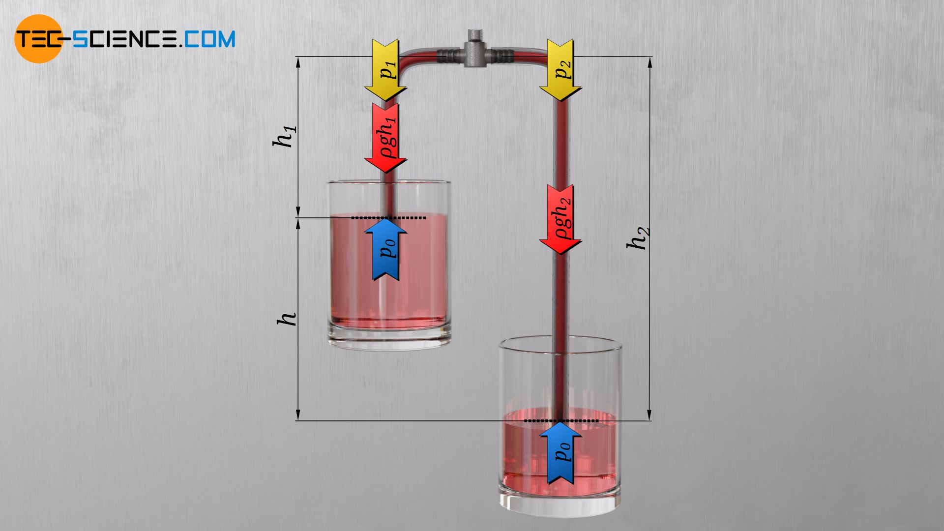
The immersion depth of the tube ends in the respective reservoirs plays no role for the equilibrium, since the hydrostatic pressure of the surrounding water would in any case press the water in the tube to the same level (principle of communicating vessels). The same ambient pressure p0 acts not only outside but also inside the hose at the water level. This upward acting pressure is obviously in equilibrium with the downward acting hydrostatic pressure of the water column in the tube (ϱ⋅g⋅h) and the downward acting pressure p1 or p2 above the water column:
\begin{align}
&p_0 \overset{!}{=} p_1 + \rho \cdot g \cdot h_1 \\[5px]
&p_0 \overset{!}{=} p_2 + \rho \cdot g \cdot h_2 \\[5px]
\end{align}
For the pressures to the left and right of the stopcock applies:
\begin{align}
&p_1 = p_0 – \rho \cdot g \cdot h_1 \\[5px]
&p_2 = p_0 – \rho \cdot g \cdot h_2 \\[5px]
\end{align}
Since the height h2 is obviously greater than the height h1, there is less pressure on the right side of the valve than on the left side. If the stopcock is now opened in thought, then the water obviously flows from the higher pressure in the direction of the lower pressure. The bigger the pressure difference, the stronger the water is pushed from the left side towards the right side. The pressure difference Δp is thus a measure of the driving force of the water flow. This driving force is in turn only dependent on the height difference h of the two water levels:
\begin{align}
\require{cancel}
\Delta p &= p_1 – p_2 \\[5px]
&= p_0 – \rho \cdot g \cdot h_1 – \left(p_0 – \rho \cdot g \cdot h_2\right) \\[5px]
&= \bcancel{p_0} – \rho \cdot g \cdot h_1 – \bcancel{p_0} + \rho \cdot g \cdot h_2 \\[5px]
\label{g}
&= \rho \cdot g \cdot h_2 – \rho \cdot g \cdot h_1 \\[5px]
&= \rho \cdot g \cdot \left(h_2 – h_1\right) \\[5px]
&= \rho \cdot g \cdot h \\[5px]
\end{align}
As equation (\ref{g}) states, the water flow is driven by the difference between the hydrostatic pressures in the hose sections to the left and right of the apex. This in turn is only due to the height difference h in the water levels. So as long as there is a difference in height between the upper water level and the lower water level, water can be pumped from the upper to the lower reservoir (provided that the apex of the hose is not higher than the maximum geodetic suction lift). If the water is not discharged into a reservoir but is discharged through the end of the hose directly into the open, then the height difference h refers to the end of the hose.
Law of conservation of energy
The siphon principle does not contradict the law of energy conservation, since water is transported from points of higher potential energy to points of lower potential energy, even if water flows upwards against gravity in the suction hose section.
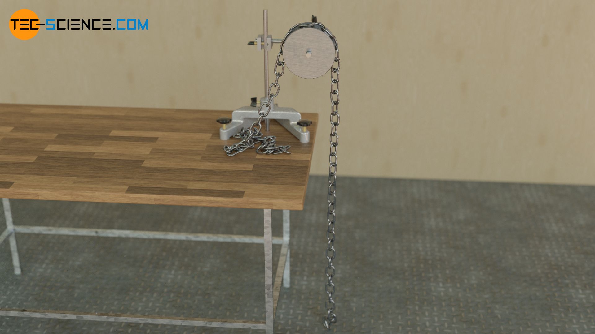
One can illustrate this situation with a chain placed over a pulley. If the chain section to the right of the idler pulley is longer and thus heavier, the greater weight will cause the chain to unroll. Only because chain links are moved upwards on the left side, this does not contradict the law of conservation of energy, since the centre of gravity of the chain moves downwards overall.
")


")
")
