A hydraulic jack is based on Pascal’s law, which states that the pressure in liquids acts equally in all directions.
Pascal’s law
In the article Pressure it has already been explained that pressure in liquids (or gases) is evenly distributed in all directions. If, for example, a certain pressure is generated at one point within a liquid, then the same pressure will be present at every other point in the liquid (neglecting the hydrostatic pressure). This is often referred to as Pascal’s law or Pascal’s principle.
Pascal’s law describes the uniform distribution of pressure in a liquid (neglecting the hydrostatic pressure)!
In some literature, Pascal’s law is also somewhat more general and then takes hydrostatic pressure into account. In this more general sense, Pascal’s law states that the pressure at a certain depth h in a liquid results from the sum of the pressure at the liquid surface p0 and the hydrostatic pressure ph:
\begin{align}
&p(h) = p_0 + p_h~~~~~\text{and} ~~~p_h= \rho g h \\[5px]
&\boxed{p(h) = p_0 + \rho g h} ~~~~~\text{Pascal’s law} \\[5px]
\end{align}
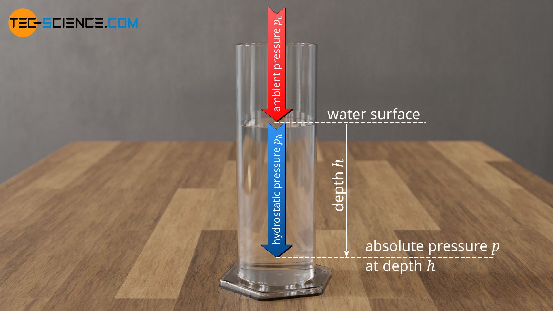
For liquids in an open container, the pressure at the liquid surface corresponds to the ambient pressure (“atmospheric pressure”). If the liquid is not very deep, the hydrostatic pressure can usually be neglected compared to the larger ambient pressure at the surface. If, for example, the depth is in the order of a few centimetres, then the hydrostatic pressure is about a thousand times lower than the atmospheric pressure. In this case, it immediately becomes apparent that the same pressure exists at every depth:
\begin{align}
\require{cancel}
& \text{with} ~~~~~ p_0 \gg p_h ~~~~~\text{applies:} \\[5px]
&p(h) = p_0 + \bcancel{\rho g h} \approx p_0 \\[5px]
&\boxed{p(h) = p_0} ~~~~~\text{valid under negligence of the hydrostatic pressure} \\[5px]
\end{align}
By neglecting the hydrostatic pressure, the pressure in a liquid corresponds to the pressure that the environment exerts on the liquid surface. The pressure in a liquid can therefore be changed by increasing the pressure on the liquid surface. However, since the surrounding air pressure cannot be changed, the liquid must first be enclosed in container. Through an opening in the vessel wall, the pressure on the liquid surface can now be increased at will by means of a piston, thus forcing a certain pressure on the liquid.
This simple principle is used, for example, in syringes. The liquid to be applied is contained in a cylindrical housing (barrel), on which a pressure is exerted with a piston. The resulting pressure causes the liquid to be pressed out of the orifice.

Hydraulic jack
Hydraulics
Another use of Pascal’s principle is the hydraulic jack or hydraulics in general. Hydraulics uses fluid to transmit energy. In addition to electrics (power transmission with electric current) and pneumatics (power transmission with air), hydraulics is of great importance in mechanical engineering.
While pneumatics refers to the power transmission with compressible gases, hydraulics refers to the power transmission with incompressible fluids!
Special oils, so-called hydraulic fluids, are used in hydraulics. Compared to water, which could only be used in a temperature range between 0 °C and 100 °C, hydraulic fluids can be used in larger temperature ranges. In addition, the hydraulic fluids not only protect metallic components against corrosion, but also provide excellent lubrication of the moving parts.
Hydraulic principle
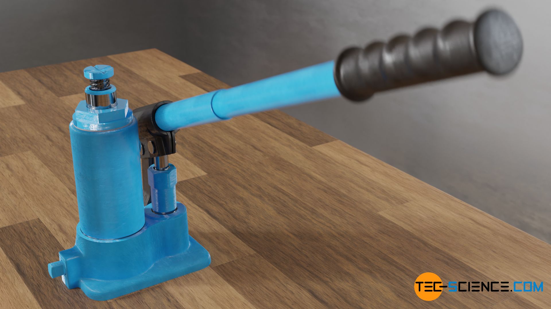
The figure below shows a hydraulic jack. A lever is used to pressurise a hydraulic fluid by a piston, thereby moving another piston upwards with great force. With such a hydraulic jack, loads of up to several tons can be lifted. The increase in force is in part due to the Pascal principle.
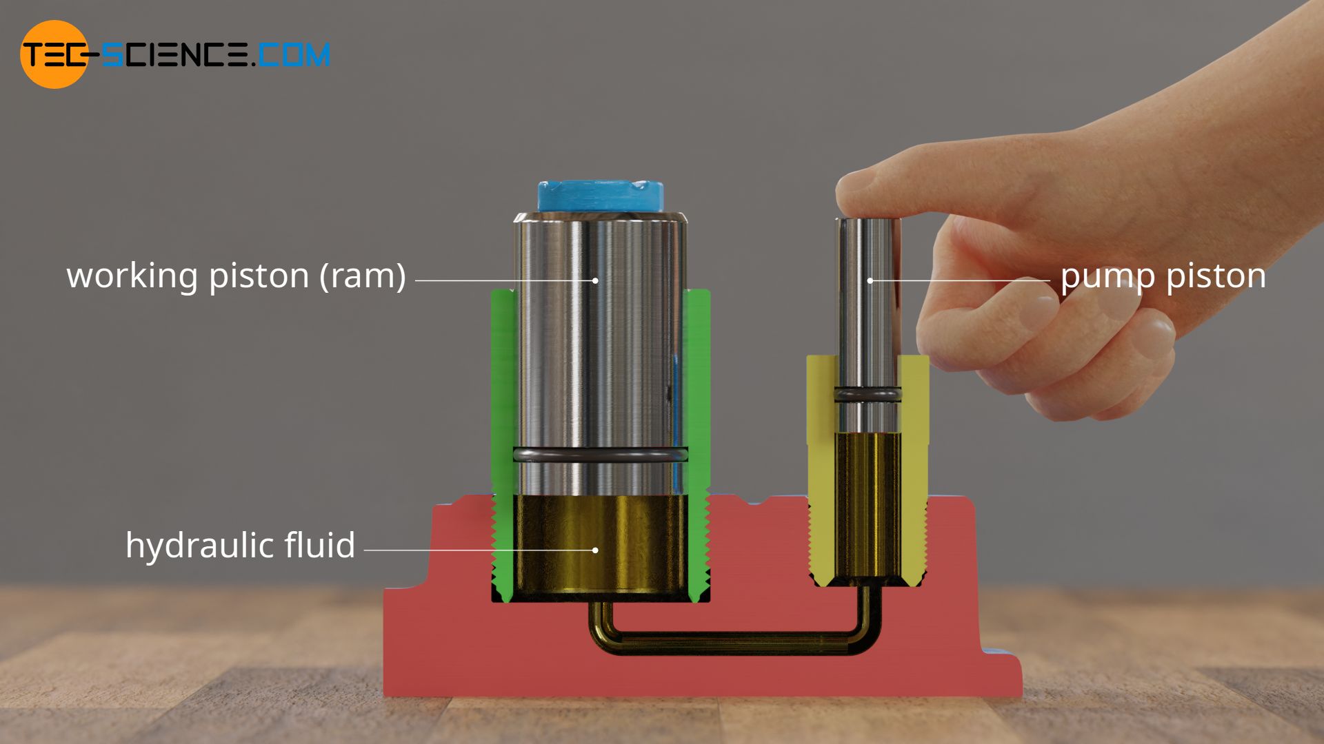
The figure below shows the simplified design of a hydraulic bottle jack, which shows the principle of operation. The hydraulic fluid is in a closed system. The housing in which the fluid is confined is provided with two pistons. The oil is put under pressure by the smaller piston (called pump piston or pump plunger).
Using the applied force F1 and the surface area of the piston A1, the exerted pressure p can be determined relatively easily from the quotient of force and area:
\begin{align}
\label{p}
&p = \frac{F_1}{A_1} \\[5px]
\end{align}
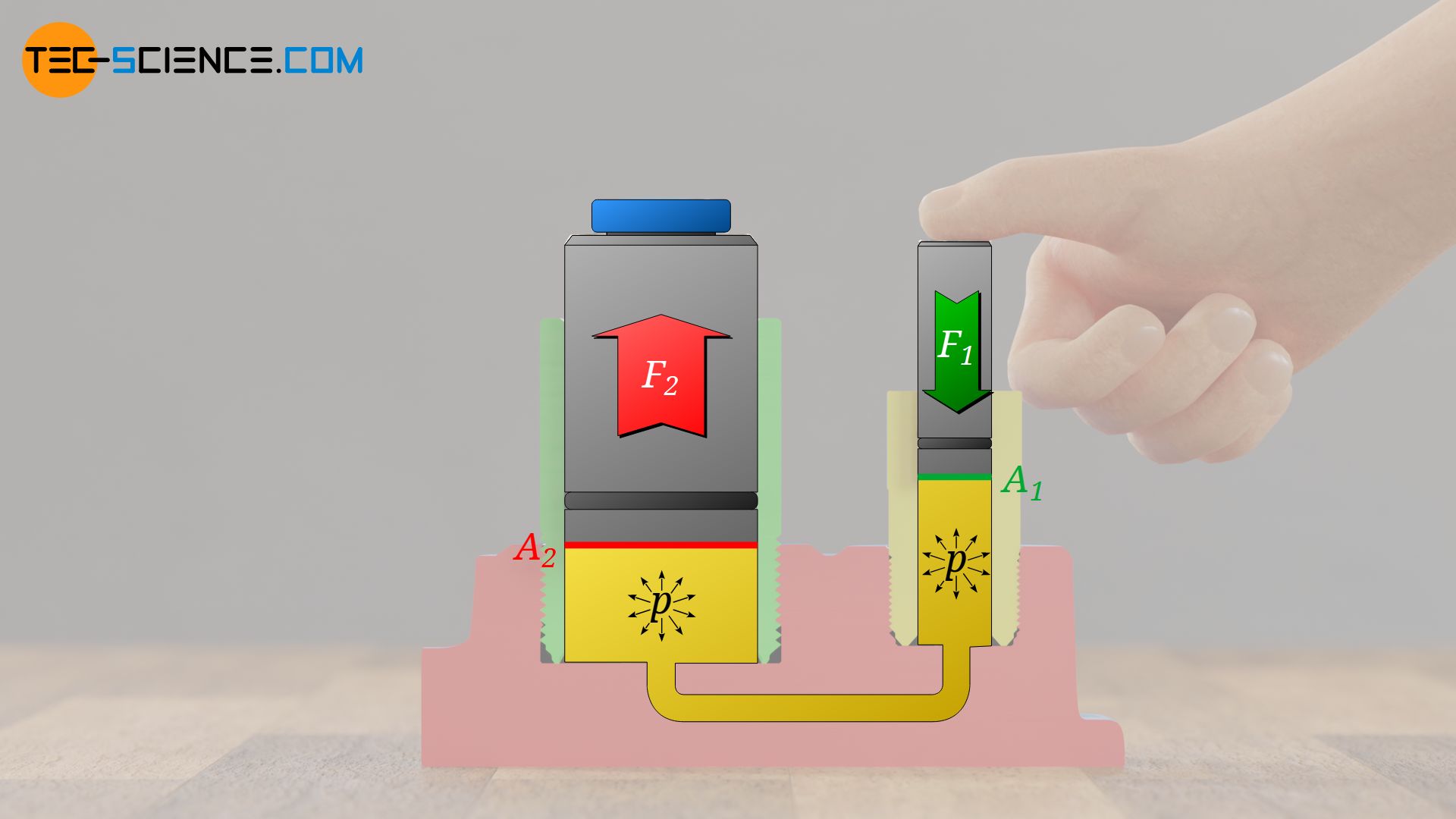
According to Pascal’s law, this pressure can be found at any point of the liquid. Note that due to the large pressures applied and the relatively small dimensions of the housing, the hydrostatic pressure can be neglected anyway. The pressure generated by the small piston therefore also acts on the second piston, called ram (working piston). However, since this piston has a larger surface area A2, the pressure there leads to a larger force F2:
\begin{align}
\label{f}
&F_2 = p \cdot A_2 \\[5px]
\end{align}
If equation (\ref{p}) is used in equation (\ref{f}), the amplification of the force is directly dependent on the ratio of the piston areas:
\begin{align}
&F_2 = p \cdot A_2 = \frac{F_1}{A_1} \cdot A_2 = F_1 \cdot \frac{A_2}{A_1} \\[5px]
&\boxed{F_2 = F_1 \cdot \frac{A_2}{A_1}}\\[5px]
\end{align}
If, for example, the area of the working piston is four times as large as that of the pump piston (i.e. the diameter of the working piston is twice as large), the force applied is quadrupled. This does not contradict the law of energy conservation! Due to the quadruple piston surface, the working piston extends by only a quarter of the pump stroke.
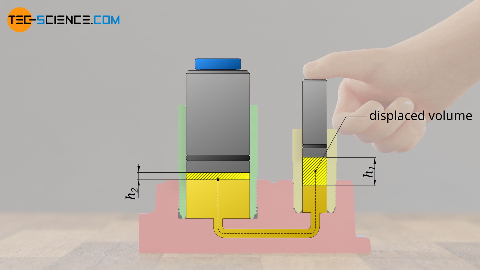
This is also clearly illustrated, as the pump piston displaces a certain amount of hydraulic fluid during the downward movement (height h1). Liquids are incompressible and therefore cannot be compressed. Therefore the displaced liquid extends the working piston by the same volume (height h2). However, the ram has an area four times as large, so that this volume is already achieved with a quarter of the original stroke. As the force is increased, the lifting height is reduced accordingly.
Mechanical principle
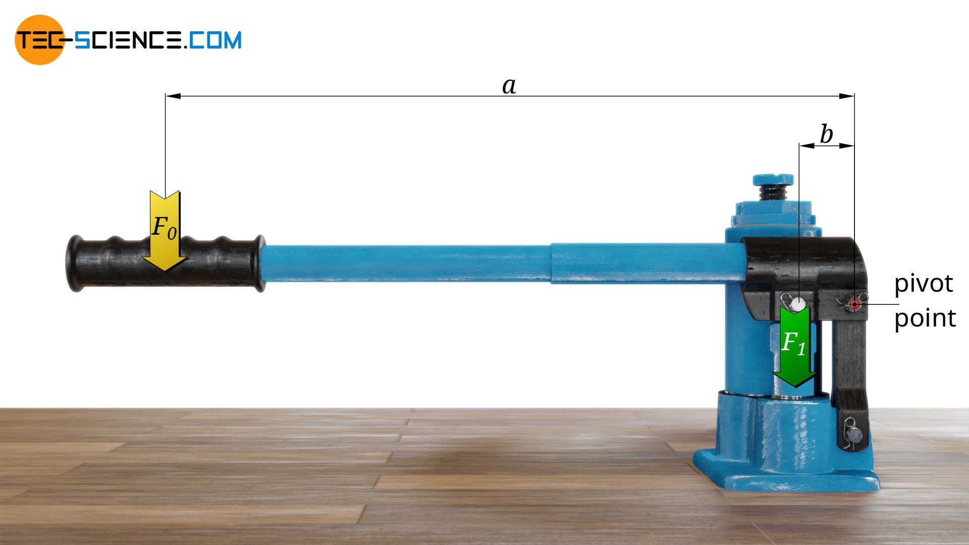
In fact, this hydraulic amplification of the force is only one of a total of two principles applied to a jack. The much greater force amplification is due to the mechanical leverage. Usually it is a second class lever.
According to the law of the lever, the mechanical amplification of the force results from the ratio of the lever arms. The “active” lever arm “a” results from the pivot point to the handle and the passive lever arm “b” from the pivot point to the pump piston. If the lever arm “a” from the pivot point to the handle, for example, is 10 times as large as the distance b from the pivot point to the pump piston, then the force will be increased by a factor of 10.
If the above mentioned figures are used as an typical example for a car jack, a mechanical amplification of factor 10 is obtained according to the law of the lever and a hydraulic amplification of factor 4 according to Pascal’s Law. In this case, a total amplification of factor 40 is obtained. Thus, an object weighing 400 kg can be lifted with an effort of 10 kg.
Construction of a hydraulic jack
The figure below shows the structure and operating principle of a real hydraulic bottle jack. The hydraulic fluid is located in a reservoir between two cylinders; an outer cylinder (oil tank) which forms the housing wall and an inner cylinder in which the working piston (ram) slides. The hydraulic fluid inside this reservoir is not pressurized all the time! During the upward movement of the pump piston (pump plunger), the hydraulic oil is sucked into the pump cylinder by an inlet passage.
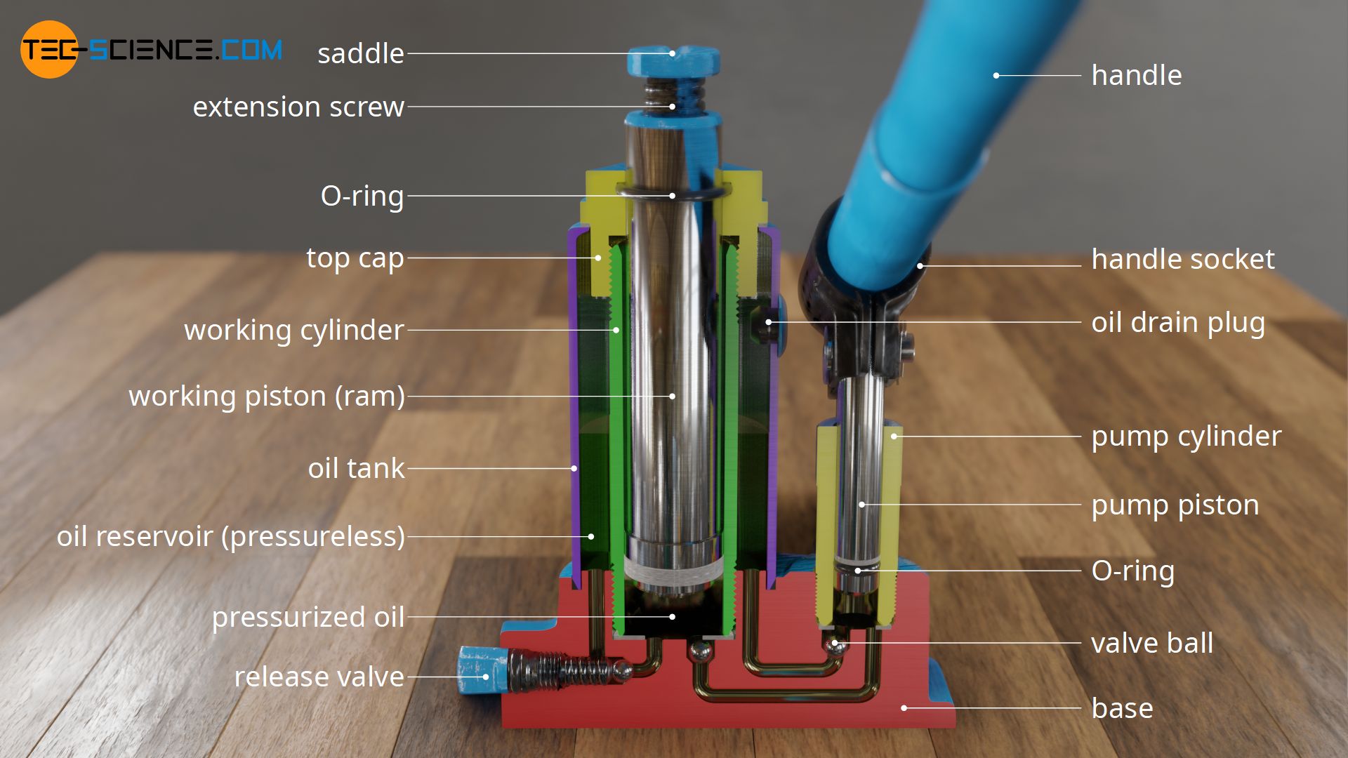
The oil is then pressurised during the downward movement of the pump piston. This causes the oil to flow through another passage into the working cylinder, where it lifts the ram.
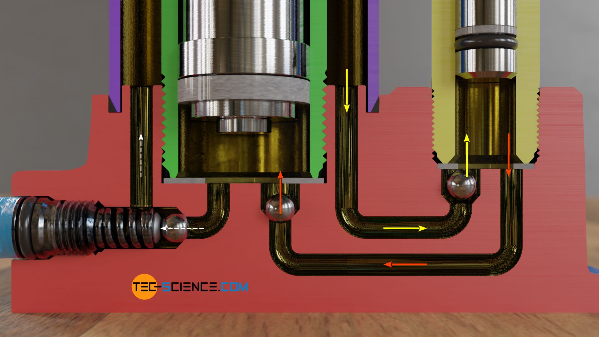
Check valves in the form of steel balls are used so that the jack can be moved continuously upwards and the hydraulic oil is not pumped back from the working cylinder into the pump cylinder (or the hydraulic oil is not pressed back into the reservoir). When the pump piston is lowered, the ball seals the way back into the reservoir. At the same time the valve ball in the working cylinder is lifted by the pressure and the hydraulic fluid can flow into it.
After the inflow, the ball in the working cylinder falls down again due to gravity. The high pressure in the working cylinder presses the ball firmly into the valve seat, thus preventing the hydraulic oil from flowing back into the pump cylinder. The pumping process can now start again from the beginning, as the ball in the pump cylinder is lifted by the suction and hydraulic fluid can be sucked into the pump cylinder. Note that due to the check valves, the hydraulic oil in the working cylinder is kept permanently under pressure, while the oil in the reservoir always remains unpressurized.
To lower the ram again, another passage is opened, which connects the working cylinder directly to the reservoir. During lifting, this passage is sealed with a steel ball which is pressed firmly into the valve seat with a screw. If this release valve is unscrewed, the ball releases the passage and the hydraulic oil is pushed back into the reservoir under the force of gravity of the ram.
In order to protect the jack from damage in the event of overload, the release valve is designed as a safety valve and is usually provided with a spring. If the pressure is too high, the spring is pushed back and the hydraulic oil can flow directly back into the reservoir without an unacceptably high pressure building up in the working cylinder.
")


")
")
