In this article, learn more about the design and operation of a roots type blower and its application as a supercharger.
Operating principle
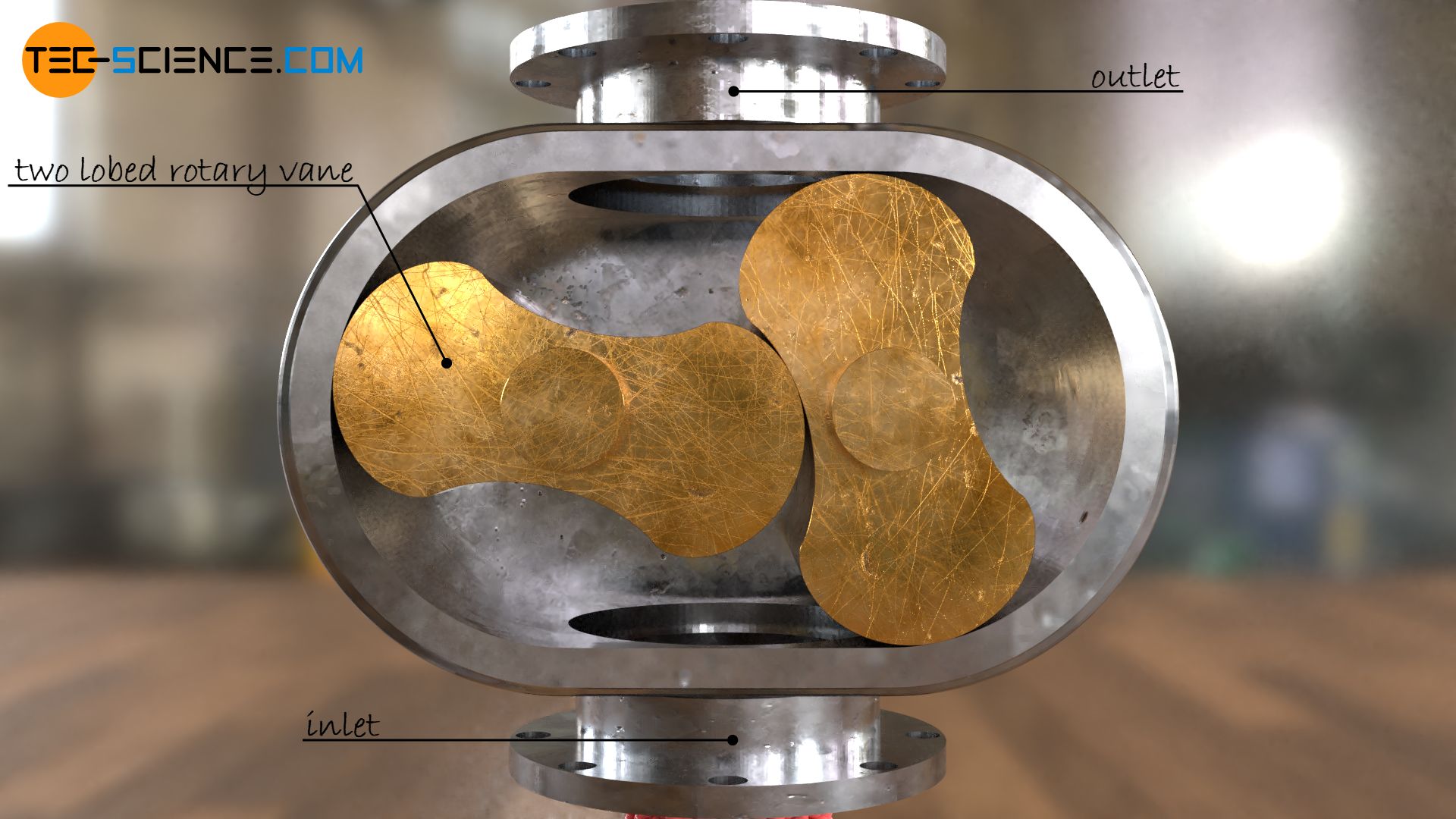
The animation below shows the operating principle of a Roots-type blower (Roots-type supercharger) with a pair of two-lobed rotary vanes (rotors), named after its inventor Francis Roots. The fluid is pumped from the suction side (inlet) to the pressure side (outlet) between the individual meshing lobes and the housing. Due to the counterpressure at the pressure side, the gaseous fluid is compressed.
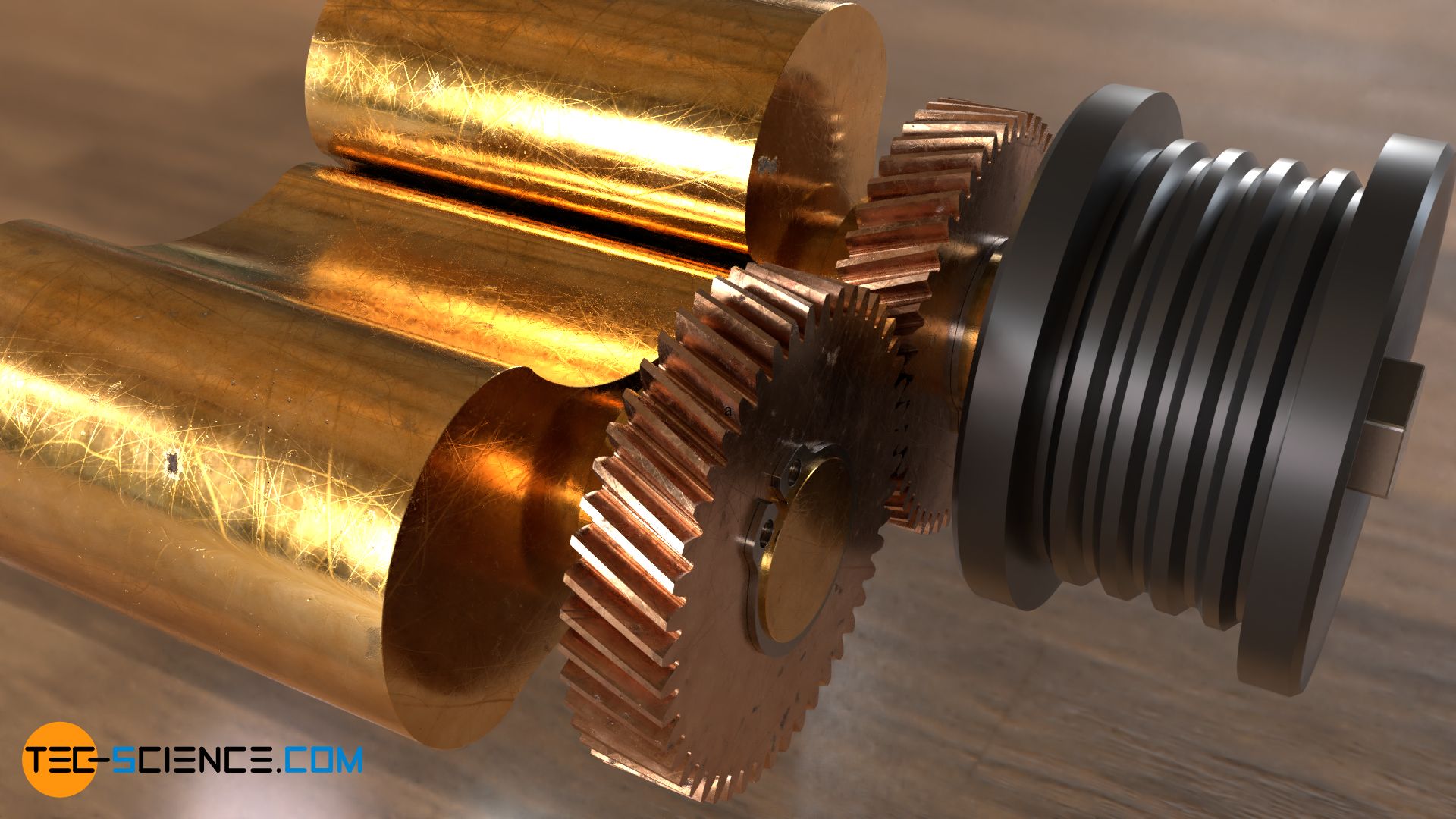
The rotors are usually driven by a belt drive and a pair of gear wheels mounted on the rear. The rotors are therefore not driven by the contact of their meshing vanes! Rather, even a small clearance must remain between the rotary vanes, as otherwise the high speeds would result in inadmissible heat development and the rotors would wear out rapidly.
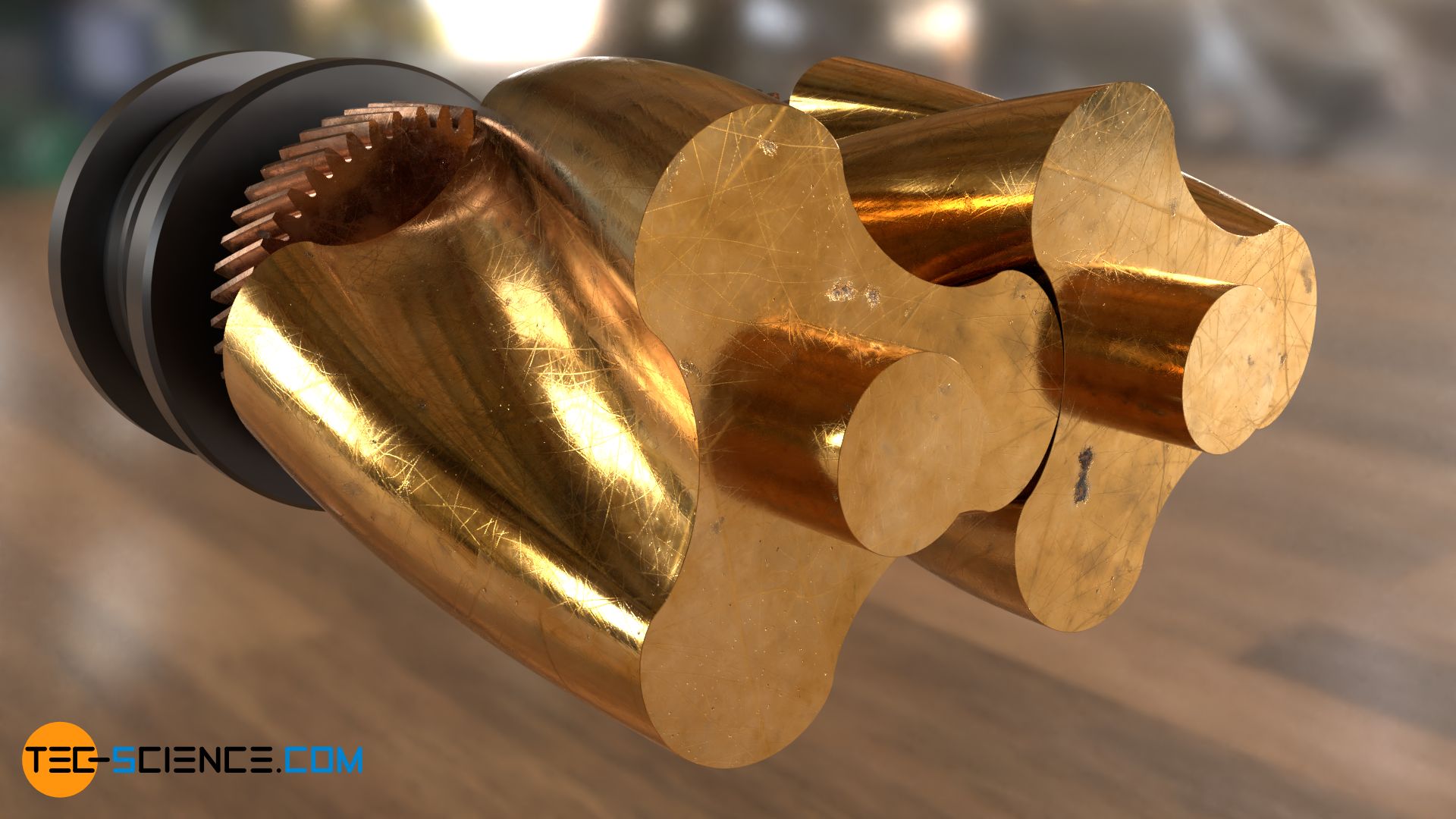
Instead of two-lobe rotors, however, three-lobe or even four-lobe rotors are usually used. In order to achieve a more continuous compression and thus avoid pressure surges, the rotors are also twisted along their axis of rotation. The cross-sectional profile of the rotors consists of cycloids. Due to the contact-free meshing, however, it is not a cycloid gearing in the true sense!
Roots-type blowers are used, among other things, as compressors for supercharging combustion engines. They are also used for pumping liquids or foodstuffs such as rice or cereals.
Roots-type supercharger
The animation below shows the structure and the functional principle of a Roots-type supercharger as it is used for charging the combustion air in automobiles.
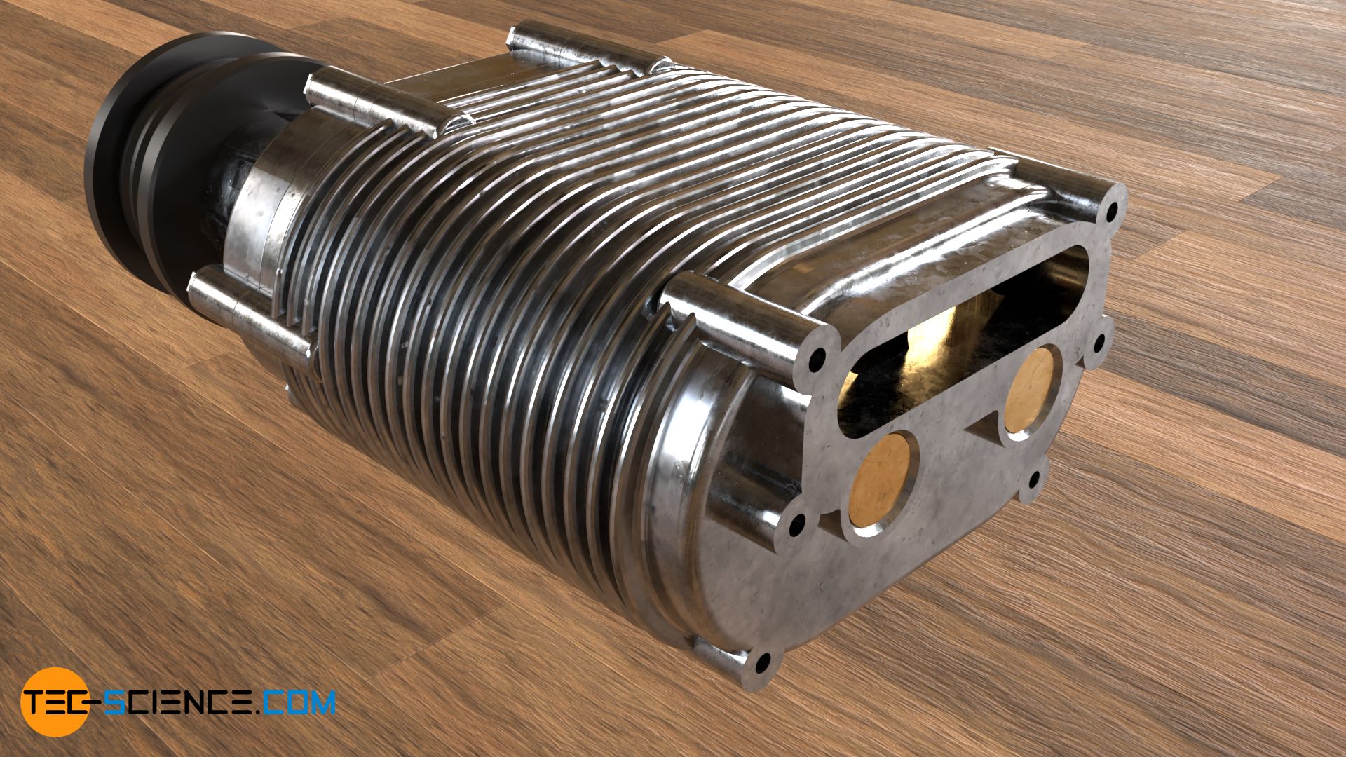
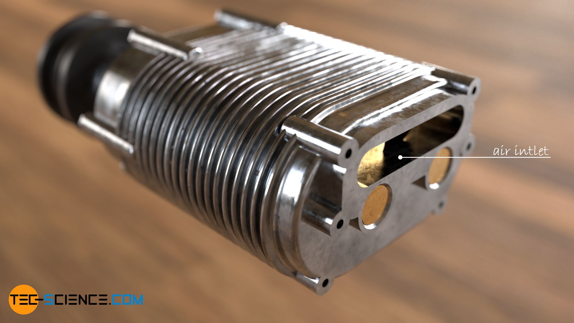
The air is sucked in through a slot at the front. The air enters the housing through this air inlet, which is equipped with cooling fins.
Inside the Roots-type supercharger are the three-lobed rotary vanes (rotors), which pump the air between the rotors and the inner wall of the housing from the suction side (top) to the discharge side (bottom). Due to the “accumulated” air on the discharge side, the pressure there increases and the air is compressed accordingly.
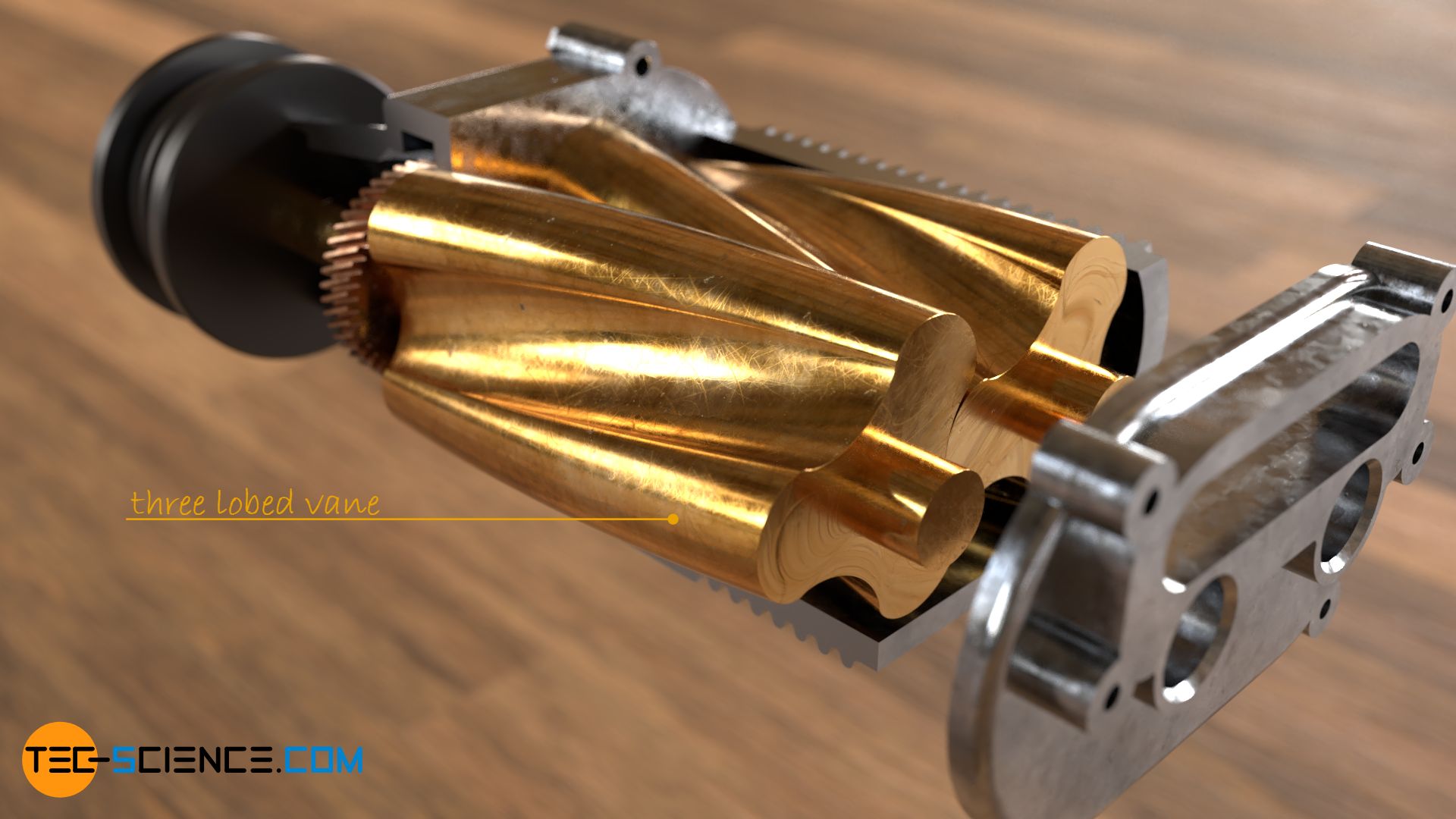
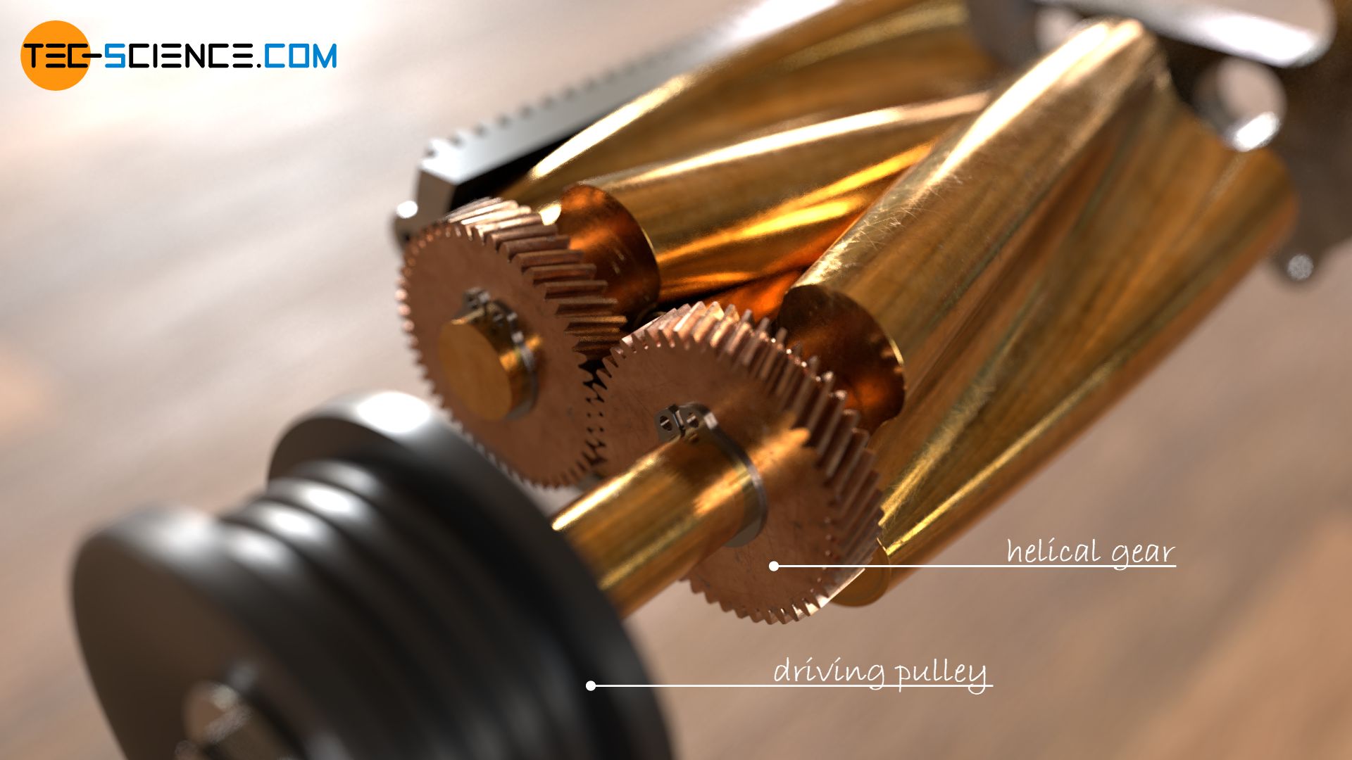
The rotary vanes are driven by a belt drive, whereby the driving pulley drives only one of the two rotors directly. The second rotor is driven by two helical gears.
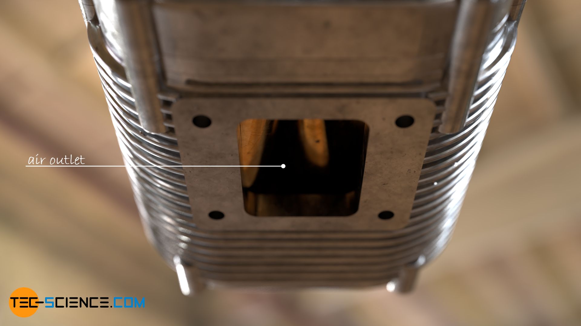
Once the air has been pumped to the pressure side, the compressed air can be used for the combustion process. The unwanted increase in temperature during compression is counteracted by the cooling fins on the housing.
The pressure ratio between the pressure side and suction side of a Roots-type supercharger is generally a maximum of 2. Depending on the rotational speed, the efficiency in these cases is around 50 %. With larger pressure ratios, the efficiency decreases rapidly! Basically, the smaller the pressure ratio, the more efficient Roots-type superchargers are.
Design of the rotors
The shape of the rotors in Roots-type blowers is made up of cycloids in the same way as cycloid gears. However, there is no power transmission between the rotary vanes as is the case with cycloid gears!
Two-lobed rotary vane
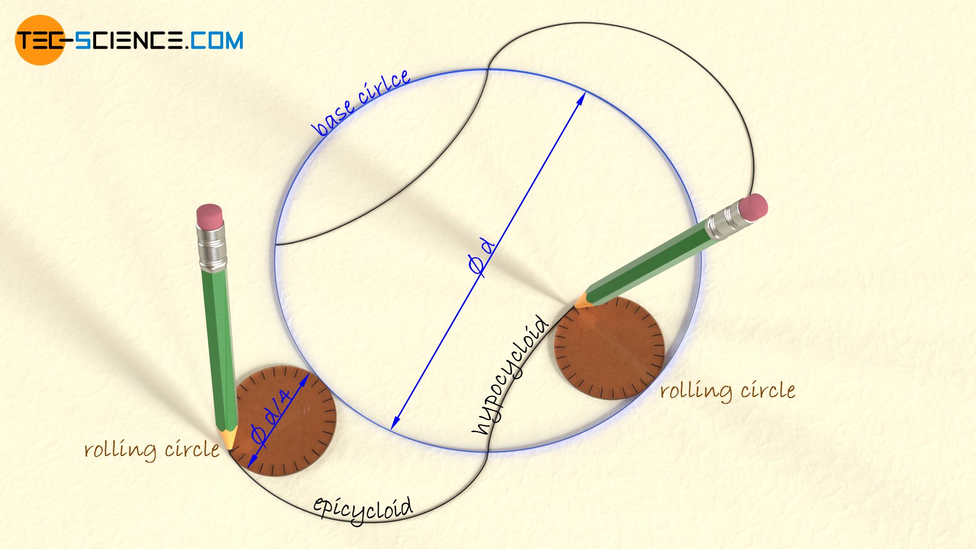
For the construction of two-lobed rotor, the rolling circles for the epicycloids and the hypocycloids are chosen to a quarter of the diameter of the base circle (see article “Geometry of cycloidal gears“).
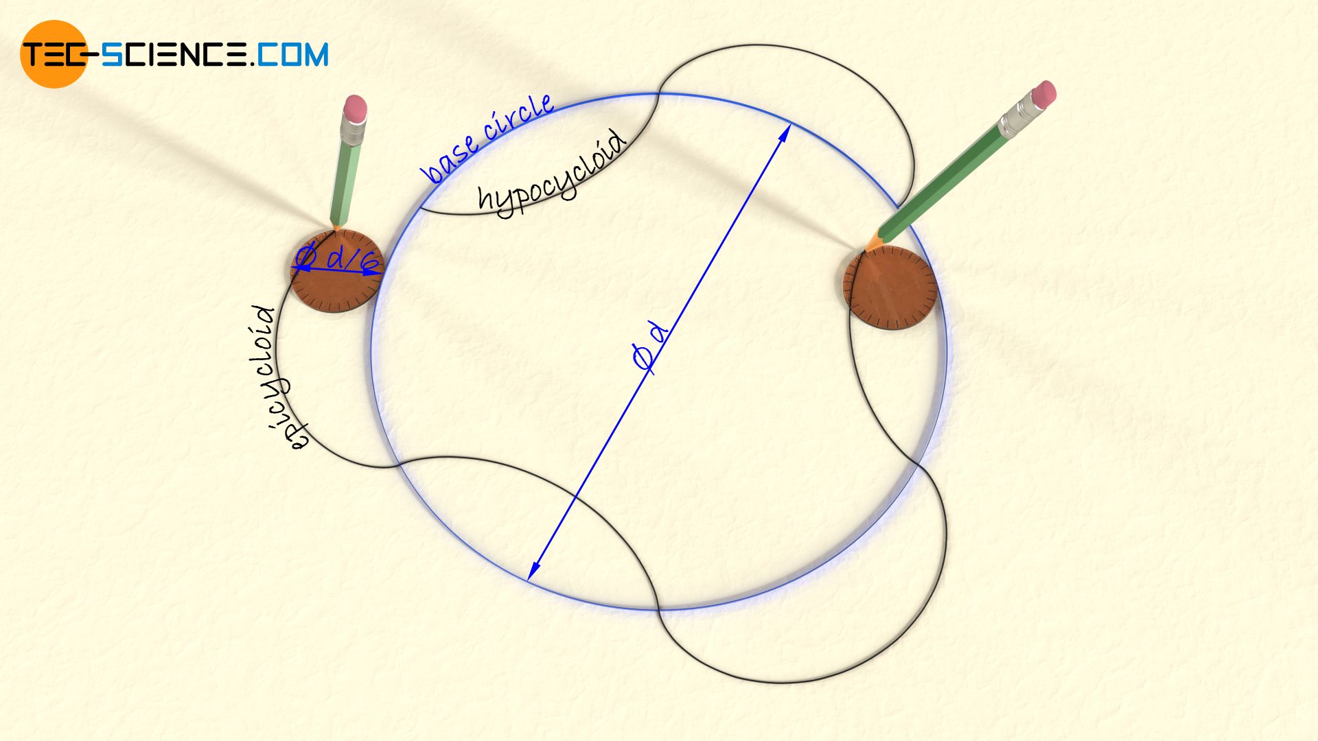
Three-lobed rotary vane
For the construction of a three-lobed rotor, the rolling circles for creating the hypocycloids and epicycloids are to be chosen to a sixth of the diameter of the base circle.