In bevel gears, the axes of the gears are at right angles to each other. Bevel gears are used to change the spatial direction of rotation.
Introduction
In contrast to cylindrical gears, where the rotary axes are always arranged parallel to each other, the axes of gear shafts can be rotated by any angle by using bevel gears. A shaft angle of 90° is often found. A gearbox with non-parallel axes is often referred to as an angular gear.
In bevel gearboxes, the axes of the bevel gears are usually perpendicular to each other!
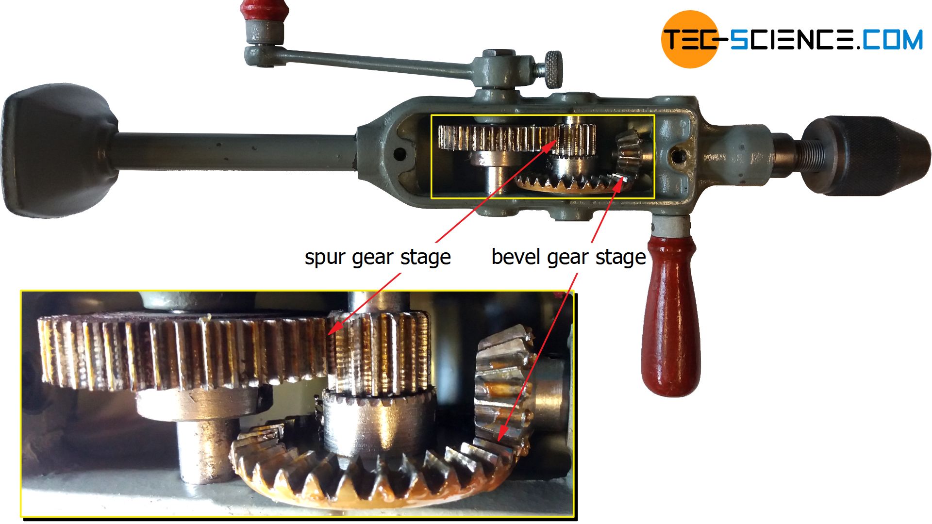
The figure below shows an example of a hand drill. While the first gear stage is a spur gear, the second gear stage is a bevel gear which also serves to rotate the axis of rotation by 90°. The speed of the crank shaft is increased with gear stage in order to obtain a high rotational speed of the drill bit.
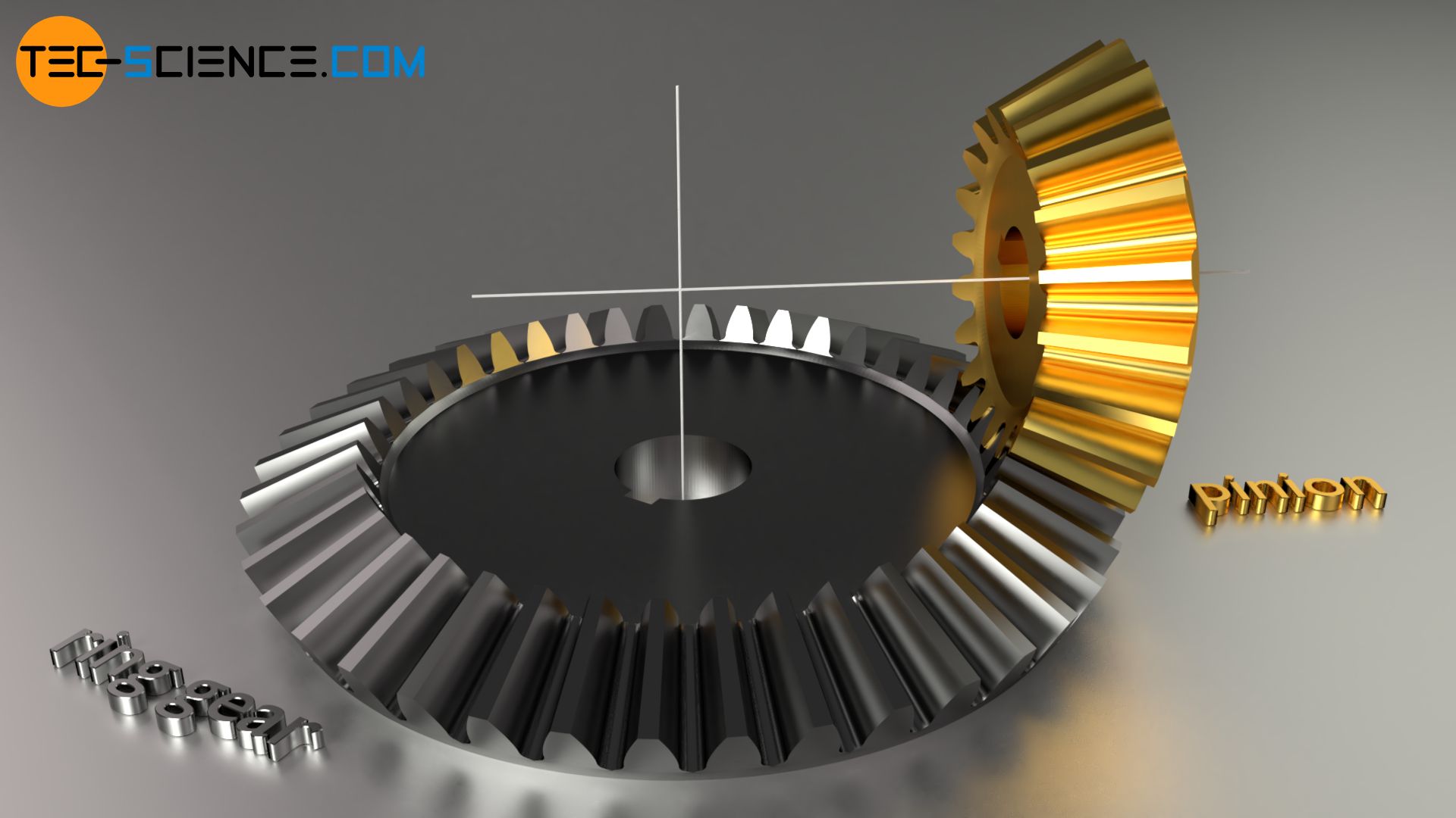
Due to its ring-shaped appearance, the larger of the bevel gears is also referred to as the ring gear. The ring gear itself is driven by a smaller bevel gear, which is then also called a pinion.
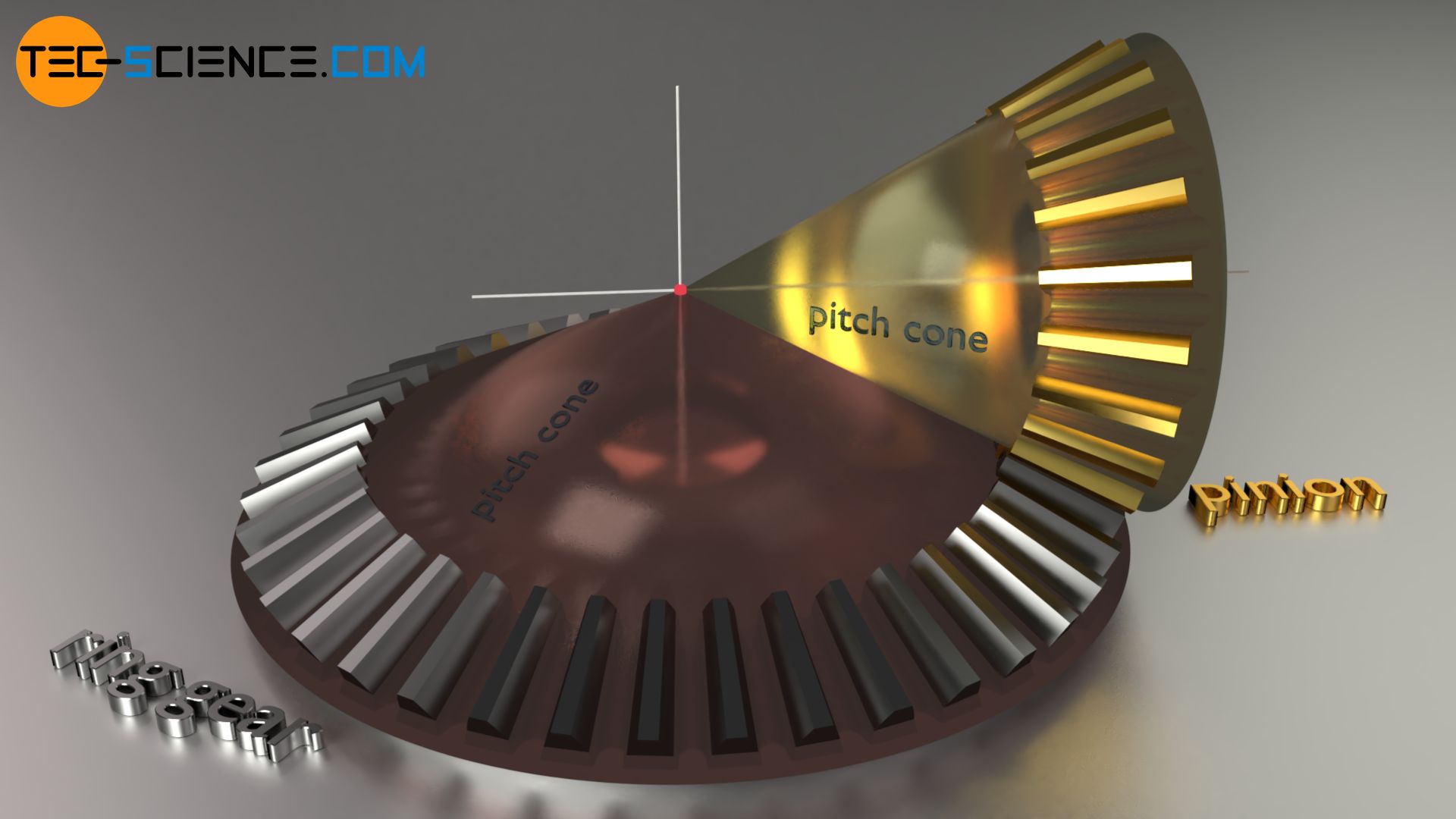
Pitch cones
With bevel gears, the shape of the gears forms a truncated cone (called pitch cone), whereby the teeth are arranged on the lateral surface. The imaginary pitch cones of two paired bevel gears roll onto each other without sliding. The peripheral speeds at the respective points of contact of the mating surface of the two pitch cones are thus identical.
The axes of the bevel gears intersect at one point, whereby the intersecting angle is usually 90°. This intersection corresponds to the point at which the tips of the imaginary pitch cones intersect when they are no longer regarded as truncated cones but as pointed cones.
Types of toothing
As with cylindrical gears, bevel gears can also have different tooth lines. The most important toothings are described in more detail in the following sections.
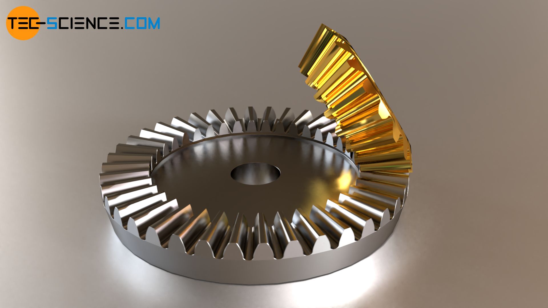
Straight cut tooth line
If the teeth run in a straight line, i.e. in the radial direction to the rotational axis of the gearwheel, this is referred to as straight cut bevel gear.
Such a straight cut toothing has the disadvantage already explained in the article cylindrical gears that the sudden onset of the complete face width causes high noise levels. However, this can be counteracted with spiral tooth lines described in more detail below.
Spiral tooth line
If the tooth flank line no longer runs radially outwards but with a certain twist (similar to helical toothing on cylindrical gears), then an spiral tooth line is obtained (spiral bevel gears). The spiral shape can also be involute, cycloidal or circular.
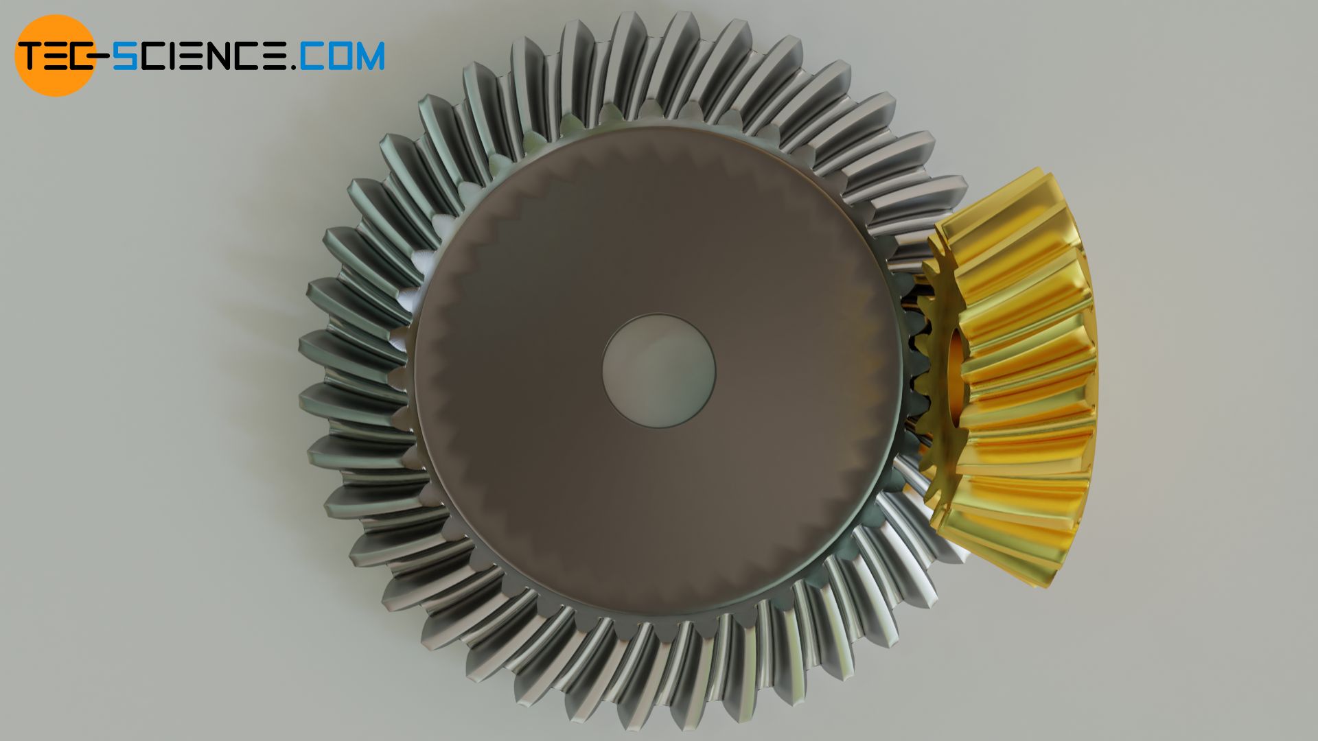
Compared to straight cut bevel gears, spiral bevel gears offer more favourable meshing conditions, higher transmissible torques and lower noise levels as well as higher installation tolerances. For this reason, spiral bevel gears are preferably used in mechanical engineering.
Planar (crown) gear
A special case of a bevel gear occurs when the pitch angle (cone angle) of the ring gear is chosen to be larger and larger and in extreme cases is 90°. The “height” of the pitch cone becomes smaller and smaller and, in the extreme case of 90°, has become a flat plane. Such a bevel gear is referred to as planar (crown) gear. The mating gear to the planar gear is a conventional bevel gear, without which a pure rolling process on the pitch plane of the planar gear would not be possible, as the circumferential speed on the rotating pitch plane decreases inwards.
Thus an shaft angle of 90° cannot be achieved with a planar gear, since the pinion would then have to be a cylindrical spur gear. However, the pitch cylinder of a spur gear has a constant circumferential speed and cannot therefore adapt to the different circumferential speeds of the planar gear! This would require an adjustment of the tooth profile on the ring gear in the radial direction – see the next section on crown gears.
The planar crown gear for bevel gears can be considered in analogy to the rack for cylindrical gears. In both cases, the originally “curved” pitch body has become a plane. In the same way as the rack profile is used as a reference for the design of cylindrical gears (see article on “Gear cutting“), the planar crown gear is used as the reference gear for bevel gears.
Crown gear
A special case of an angular gear occurs when a conventional spur gear is used as a pinion, which in principle rolls on a rack that is bent into a ring. The teeth arranged in the plane resemble the teeth of a crown in their appearance. This is why one speaks of a so-called crown gear. The tooth line of a crown gear can be either straight cut or spiral.
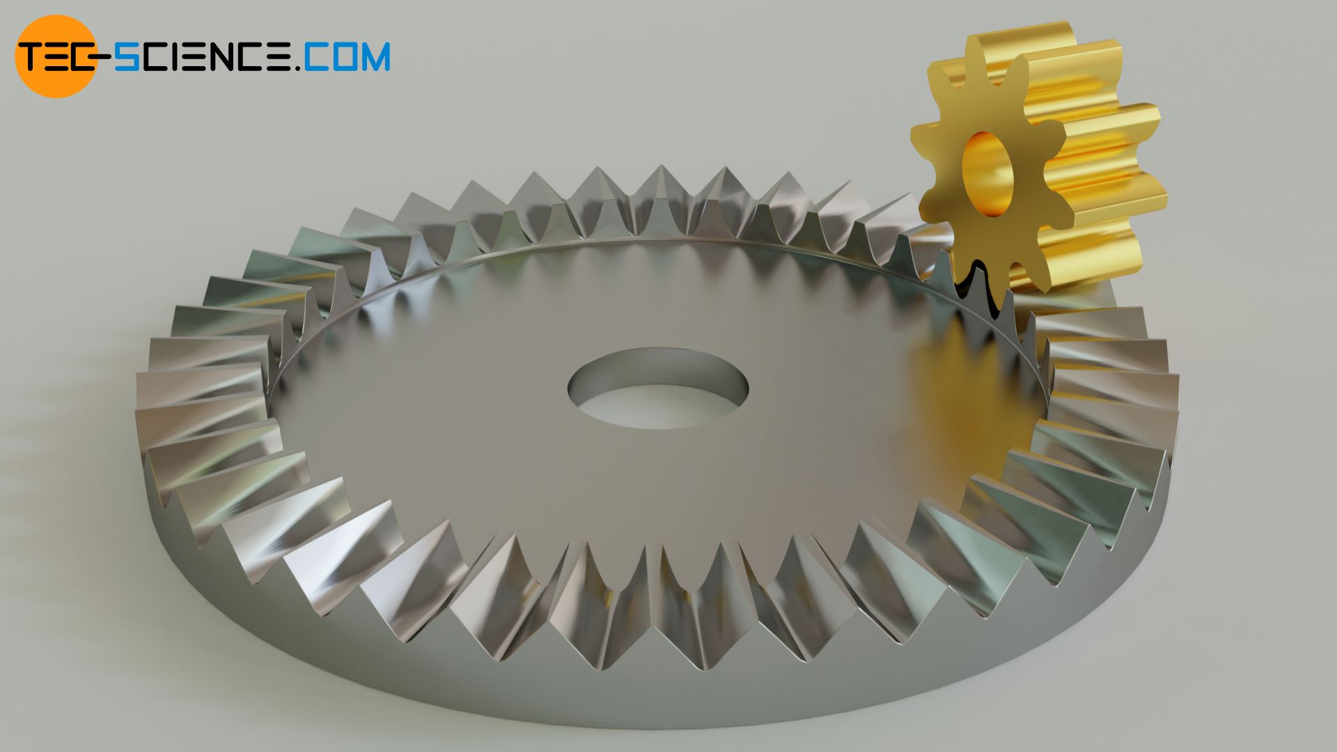
The animation above shows a straight cut crown gear driven by a conventional spur gear. In contrast to the bevel gear with a conical shape, the crown gear allows axial displacement of its mating gear! In addition, no axial forces occur as with conical bevel gears.
Since the circumferential speed of the crown gear increases towards the outside, but the spur gear has a constant circumferential speed, the tooth profile of the crown gear must be adapted in radial direction for a sliding-free rolling process of the pitch bodies (large pressure angle at the outside and small pressure angle inside).
The crown gear is not a bevel gear in the actual sense, since the pitch bodies are not cones anymore! In contrast to the planar crown gear, a shaft angle of 90° can be achieved with a regular crown gear. In general, the shaft angle can range be between 0° and 180°.
")


")
")