In this article, you can learn more about a lantern pinion as a special case of cycloidal gear.
Operating principle
A special case of cycloidal gearing with point tooth form is the so-called lantern pinion. The Animation below shows the operating principle of the lantern gear. A disc with pins (or trundles) engages with a (cycloidal) gear wheel and drives it.
Design of the lantern pinion and lantern gear wheel
The figure below shows the construction of a lantern pinion. As is usual with cycloidal toothing, a base circle is first required on which a rolling circle forms the cycloidal tooth flank. In the case of a lantern pinion, however, that the trajectory point (“pencil tip”) is no longer concentrated on a single point but is extended to form a circle (this reduces the wear on the tooth flank in later operation). The diameter of the circle corresponds to the diameter of the trundles.
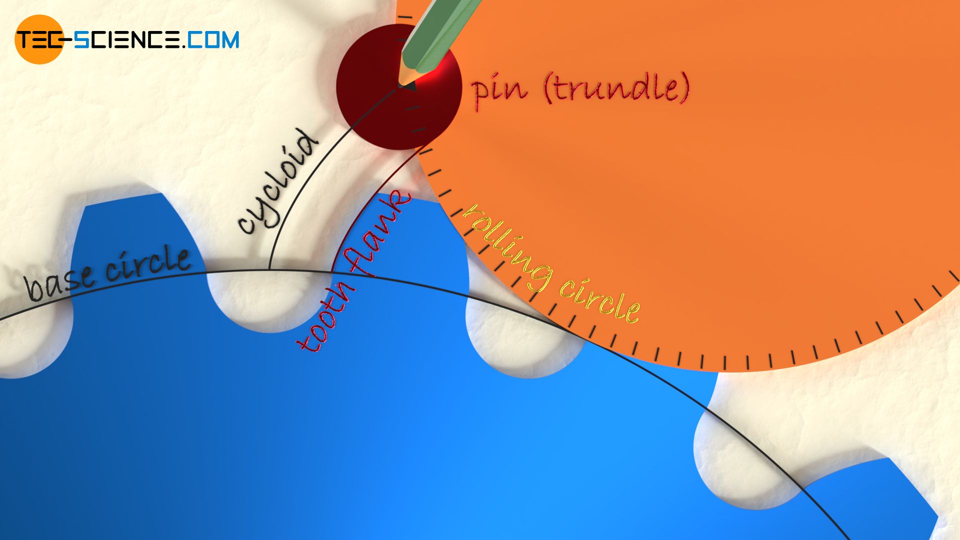
If the rolling circle is now rolled on the base circle, the envelope of the trundle circles forms the shape of the tooth flank (equidistant to the cycloid). For the construction of the lantern pinion, the trundles are arranged on the circumfarance of the rolling circle (=pitch circle) .

Lantern pinions are a very old type of gearing, which used to be frequently found in mills. At that time, wooden bars were used. Nowadays these are low-friction trundles. Lantern pinions are still used when heavy loads have to be transmitted at low speeds, e.g. for driving large telescopes. Lantern pinions are not suitable for high-precision transmissions.
Lantern pinions are used for large gearboxes with high torques to be transmitted!
Due to the much easier manufacturing, the cycloid shape of the lantern pinion gear wheel is often approximated by an involute shape in practice.
Line of action
The animation below shows the meshing of a lantern pinion. The line of action no longer runs exactly on the rolling circle, because the trajectory point on the rolling circle during the construction of the tooth flank was extended to a circle.
The line of contact is determined by the intersection between the line \(\overline{MC}\) and the trundle (with \(M\) as the center of the trundle and \(C\) as the pitch point). This is a direct result of the law of gearing, which states that the normal (= radial of the trundle) must run through the pitch point.

Since the meshing of the trundles is essentially concentrated on that part of the line of contact which lies in front of the pitch point, lantern pinions generally have relatively low contact ratios.
Lantern pinion wheel with involute toothing
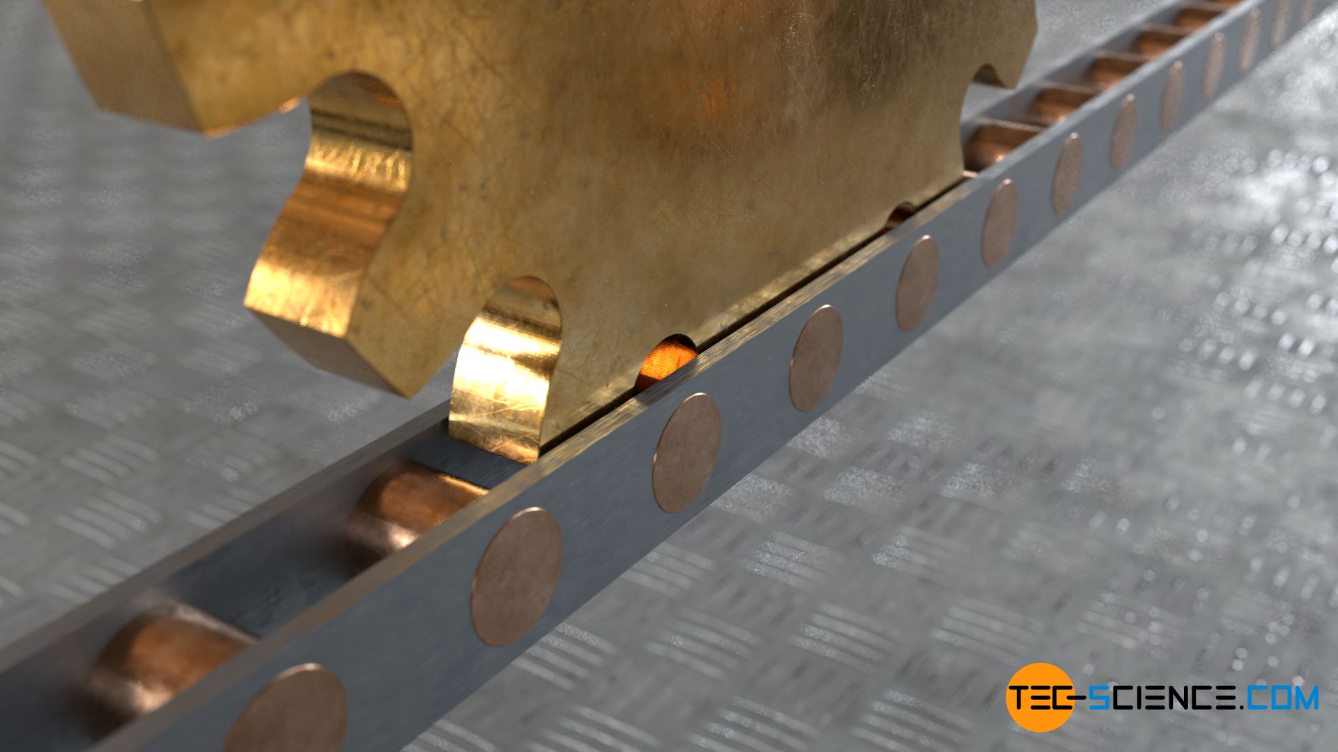
If a “rod” is used instead of a disc to which the trundles are attached (“driving rod”), the rolling circle is then a rolling straight line. If this straight line is used to construct the tooth flank of the gearwheel, one will obtain involute shape tooth flanks (involute gear wheel)!

