In this article, learn more about the meshing of the teeth of cycloidal gears.
Line of action
The figure below shows the meshing of two cycloidal gears. The dash dotted pitch circles are at the same time rolling circles and correspond to the base circles with which the cycloidal shape of the respective gear was created (see article Geometry of cycloidal gears). The rolling circles touch each other at the pitch point C. The line of contact highlighted in red, on which the tooth flanks touch, runs through this pitch point. The line of contact consists of arc sections of the rolling circles with which the cycloidal tooth form was constructed. The line of contact is limited by the point of intersection between the rolling circle (line of action) and the tip circle (addendum circle) of the opposite gear.

With cycloidal gears, the line of contact is formed by the rolling circles of the hypocycloids and limited by the tip circles of the gears!
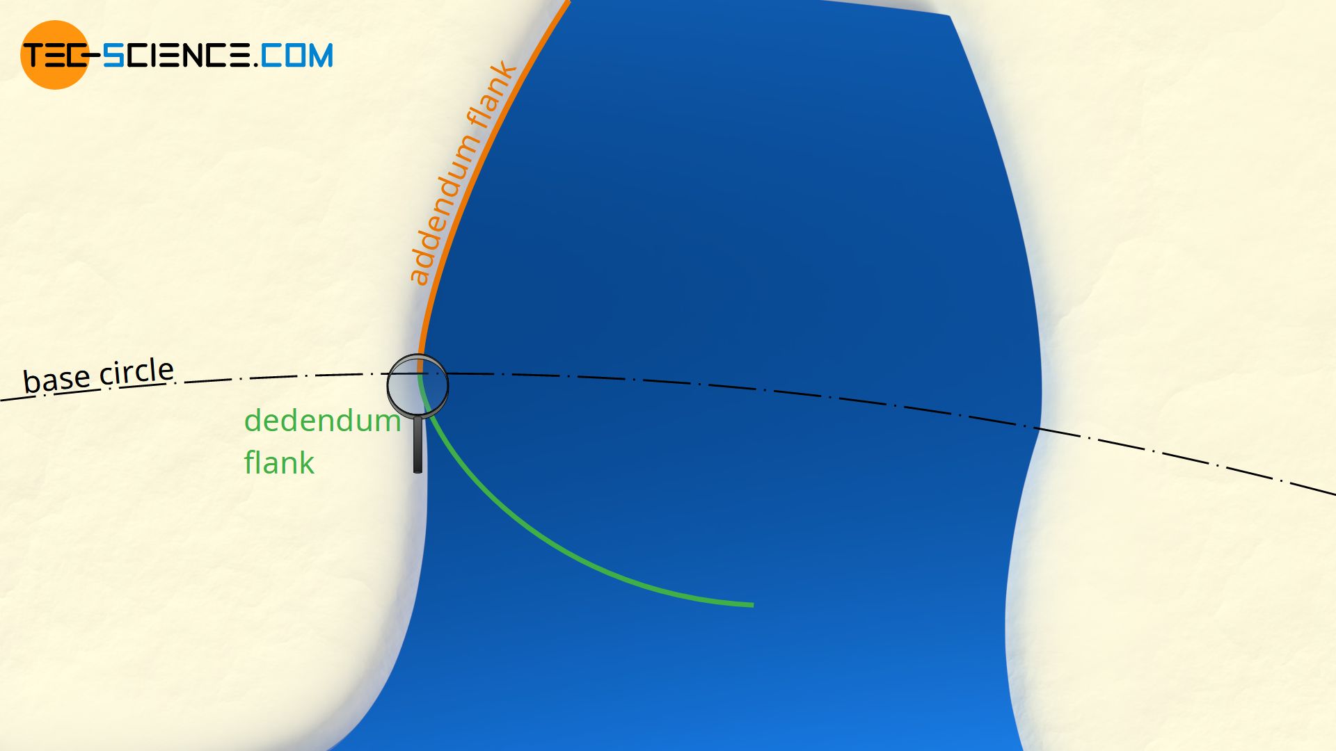
A closer look at the meshing shows that first the concave dedendum flank of the driving gear (yellow) meets the convex addendum flank of the driven gear (blue). The situation is reversed at the pitch point (inflection point of the line of contact) and the convex addendum flank of the driving gear meets the concave dedendum flank of the driven gear. Thus, a cycloidal toothing always provides a smooth flank pairing and thus a significant reduction in the surface pressure in comparison to involute toothing. This also reduces wear on the teeth. Note that with cycloidal gears, a dedendum flank of one gear will never be in contact with a dedendum flank of the other gear (the same applies to the addendum flank)!
Cycloidal gears show a relatively low flank wear compared to involute gears!
Law of gearing
The reason that cycloidal gears also satisfy the law of gearing and thus provide a constant transmission ratio is due to the fact that the rolling circles for the construction of the cycloidal tooth shape are applied equally to both gears: the rolling circle for the construction of the hypocycloid of one gear is used for the construction of the epicycloid of the mating gear and vice versa (see article Geometry of cycloidal gears).
This fact finally results in the law of gearing, which states that for a constant transmission ratio the normal at the point of contact of two flanks in mesh must always run through the pitch point C.
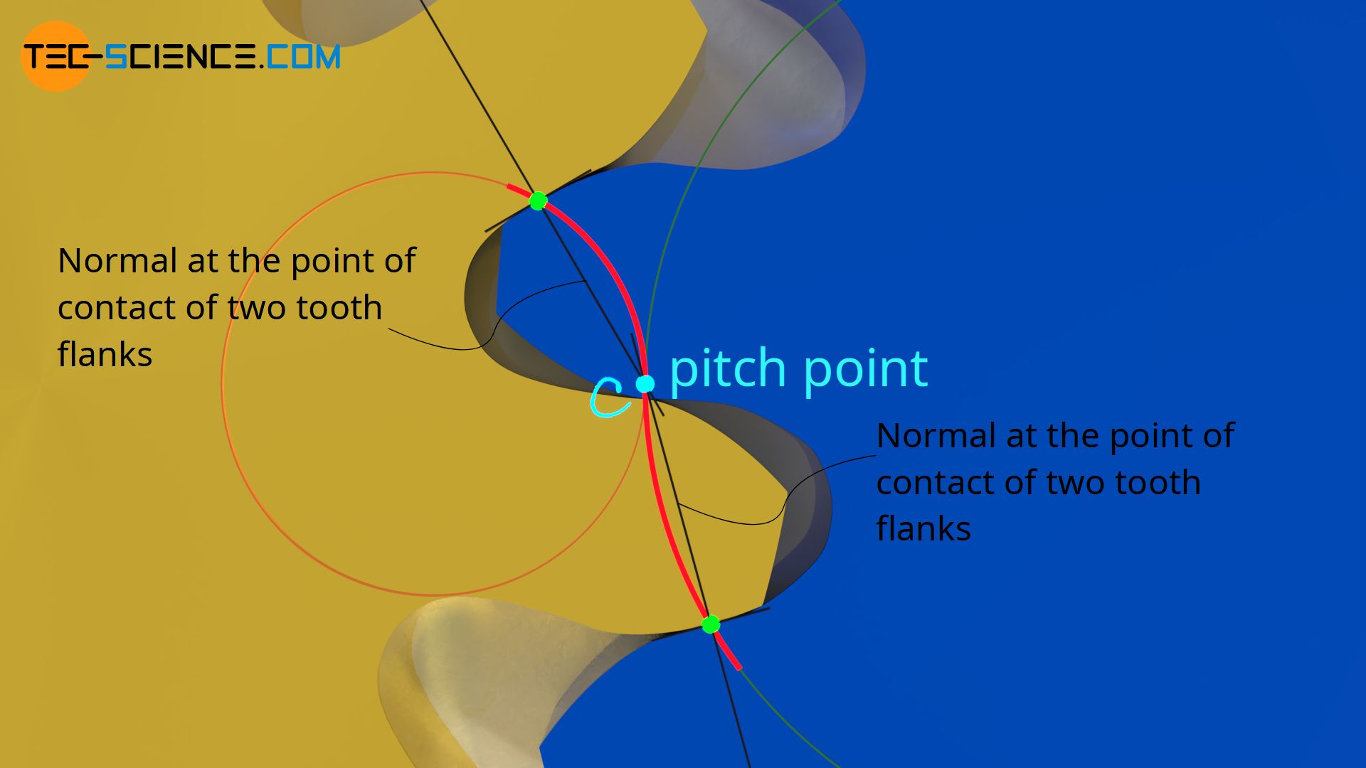
The normal at the point of contact of two tooth flanks in contact must always run through the pitch point (general law of gearing)!
If this were not the case, then the torque would vary permanently. In contrast to involute gears, the (standard reference) pitch circles of two cycloidal gears must therefore touch each other exactly (inflection point in the line of contact), i.e. the centre distance as the sum of the pitch circles radii must be maintained exactly. Since this cannot always be guaranteed (e.g. by thermal expansion), the use of cycloidal gears in classical mechanical engineering plays hardly any role.
In order to comply with the law of gearing (constant transmission ratio), the centre distance for cycloidal gears must be maintained exactly!
Point tooth form
If the rolling circle for the dedendum flank is chosen larger and larger for the construction of the hypocycloid, then the dedendum flank decreases more and more. The animation below shows the construction of the hypocycloid for a ratio of base circle to rolling circle of 0.97. However, the later tooth flank is only a fraction of this drawn hypocycloid.

The animation below shows the engagement of two cycloidal gears designed with a rolling circle to base circle ratio of 0.97. Since the rolling circle lies almost identically on the pitch circle and the rolling circle ultimately determines the line of contact, the teeth are engaged almost completely on the pitch circles.
Thus the contact point of the tooth flanks on the first part of the line of contact up to the pitch point C remains almost exclusively on the pitch circle of the yellow (driving) gear (see point A). The wear of the dedendum flank on the pitch circle is therefore very high. Only with the second part of the line of contact (i.e. from the pitch point to the end of meshing), the entire addendum flank is successively used for meshing. However, the mesh on the blue (driven) gear is now almost completely on the pitch circle (see point B).

In the limiting case where the rolling circle corresponds to the base circle and therefore the diameter ratio becomes one, the dedendum flank concentrates only on a single point. This results in a so-called point tooth form, since the entire addendum flank of the mating gear slides only on this one point. The wear of such a point tooth form is correspondingly high.
A point tooth form is favourable only with regard to the line of contact, which increases to a maximum and thus ensures a large contact ratio. The figure below shows the lines of contact for different rolling to base circle ratios.
A point tooth form shows a relatively large contact ratio; however, the wear on the tooth flank is very high!

Note: The contact ratio is determined by the ratio of the length of the line of contact to the base pitch (distance between two adjacent flanks in contact).
Due to the unfavourable wear, point tooth forms are generally of no importance. An exception to this is the so-called lantern gear, which is dealt with in the following article.


