Roughly speaking, gearboxes are divided into four types: gear drives, belt drives, chain drives and friction wheel drive.
Introduction
Transmission are available in many different types, depending on the application, e.g. as gear drive, belt drive, friction drive, worm drive, planetary drive, etc. However, the physical principle of transforming rotational speed (angular velocity) and torque or velocity and force are identical for all transmission types. However, before we go into more detail on how transmissions work, we will briefly explain the most important types. More detailed information can be found in the main articles.
Gear drive
In gear drives, gear wheels, wich are also referred to as cogwheels or toothed wheels or simply gears, engage with each other and thus form-locking convert the revolution speed and torque of the drive shaft to the desired value on the output shaft. The gearbox input shaft is referred to as the drive shaft. This corresponds to the shaft which is connected to the motor and whose speed or torque is to be changed by the gear unit. The output shaft therefore corresponds to the gearbox output.
Form-locking (or positive locking) transmissions transfer the power through interlocking geometric forms!
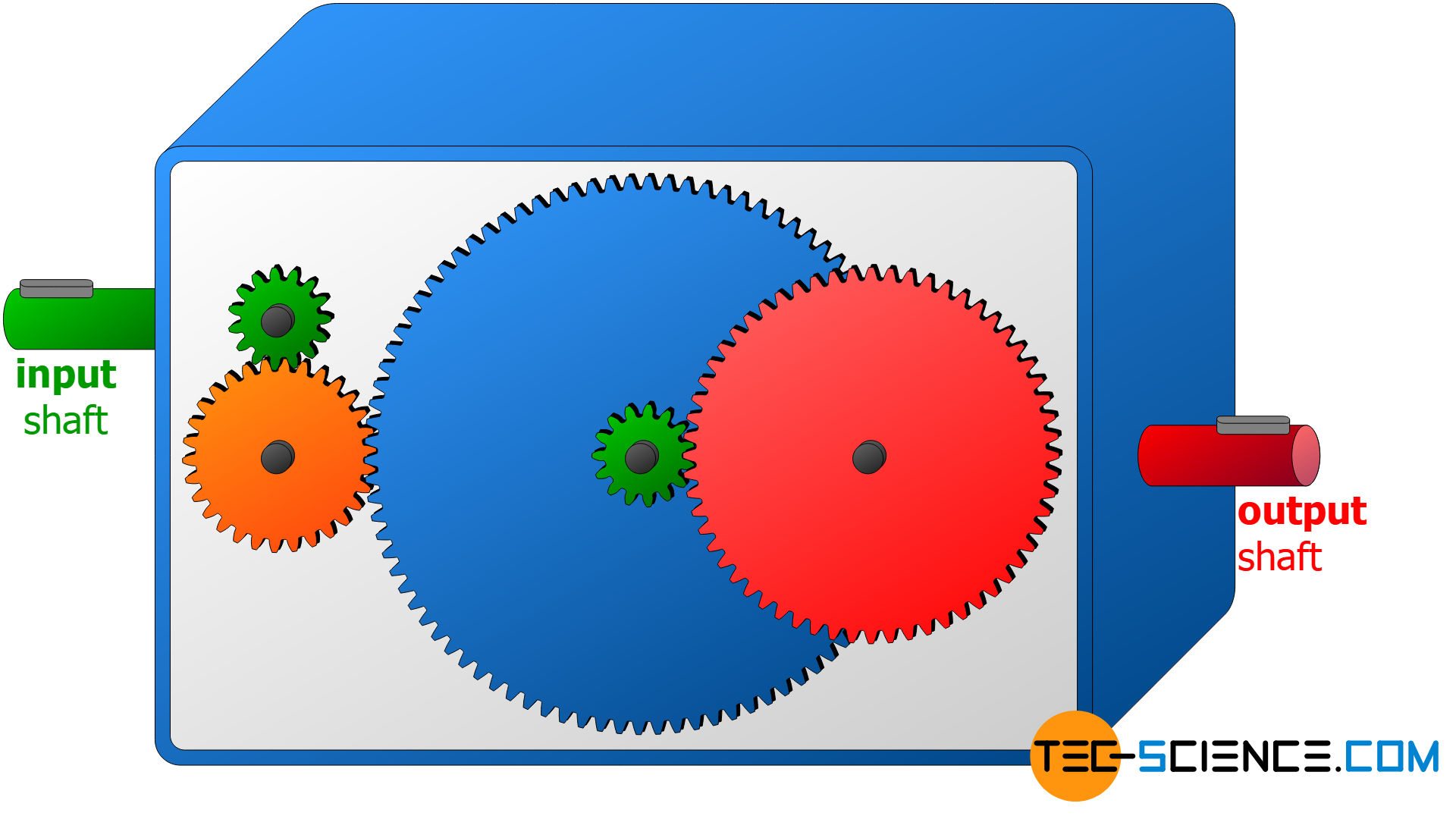
The animation below schematically shows a three-stage gear transmission. If you look at it, you will notice that the direction of rotation of the gears changes with each gear pair! If, for example, the driving gear rotates counterclockwise, the driven gear will rotate clockwise. This reversal of the direction of rotation must be taken into account when designing gear drives.
The sense of rotation changes with each gear pair (gear stage)!
Belt drive and chain drive
In belt drives or chain drives, the speed and torque are converted by wheels which drive each other via belts (belt drives) or chains (chain drives). The wheels of belt drives are also referred to as belt pulleys, and the those of a chain drives are referred to as chain wheels or sprocket wheels.
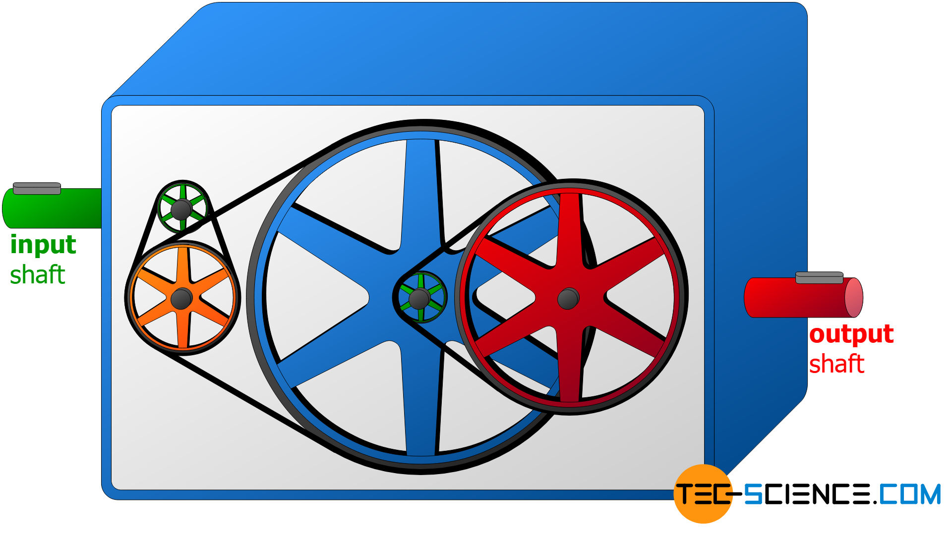
While the power transmission of chain drives is also form-locked, the power transmission of belt drives is not effected by interlocking forms but by frictional forces between belt and pulley. In such a case one speaks of a friction-locking transmission or somewhat imprecisely of a force-locking transmission.
Friction-locking (or force-locking) transmissions transfer the power through frictional forces!
The advantage of friction-locking power transmissions is the integrated overload protection. While with gear drives the teeth could break in case of overload or the chains could break in case of chain drives, with belt drives the belt is only pulled over the belt pulley in case of overload. Belt drives are therefore frequently used where many load peaks are to be expected, e.g. in cone crushers or jaw crushers for crushing stones.
The animation above schematically shows a three-stage belt drive. In contrast to gear drives or friction wheel drives (explained below), the direction of rotation of the individual pulleys does not change in the manner shown. However, this does not necessarily have to be the case with belt drives. To reverse the sense of rotation, the belts can also be crossed (crossed belt drive).
Friction wheel drive
With special friction-locking drives, the toothless wheels can also roll directly onto each other. This is then referred to as a friction wheel drive, shown in the animation below.
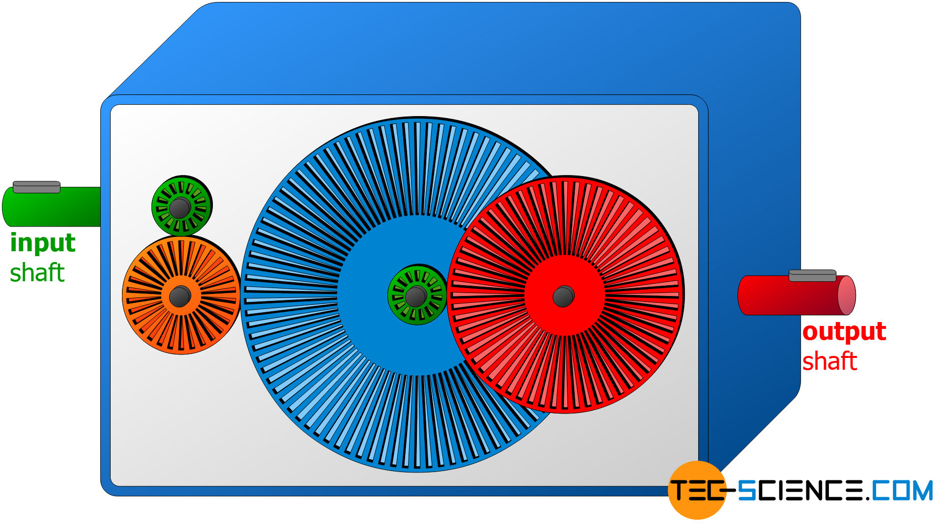
The advantage of a friction drive compared to a gear drive is that in case of overload the friction wheels simply slip onto each other and thus protect the transmission from major damage. The disadvantage, however, is the lower efficiency, as relative movements occur due to non-optimal adhesion conditions between the friction wheels. Such a minimal slipping of the wheels will always be present with friction-locking power transmission. In technical terminology, this is also referred to as slippage and reduces the efficiency. Slippage also occurs between belt and pulley in belt drives.
Slippage is the relative movement between a driving element and a driven element in friction-locking power transmissions!
The elastic deformations of the friction wheels or belts at the contact points also lead to efficiency losses, since permanent “flexing” is associated with high forces. The flexing work becomes noticeable in a warming of the wheels or the belt.
 and what is it used for?")
")


 work?")