A gear stage is a wheel pairing within a gearbox at which the speed or torque changes! Learn more about gear stages in this article.
Definition
The figure below schematically shows a toothed gear whose basic function was explained in more detail in the article Operating principle. As this animation shows, a transmission usually consists not only of one pair of gears but of several, each mounted on different shafts. Each pair of gears that meshes with each other represents a so-called gear stage.
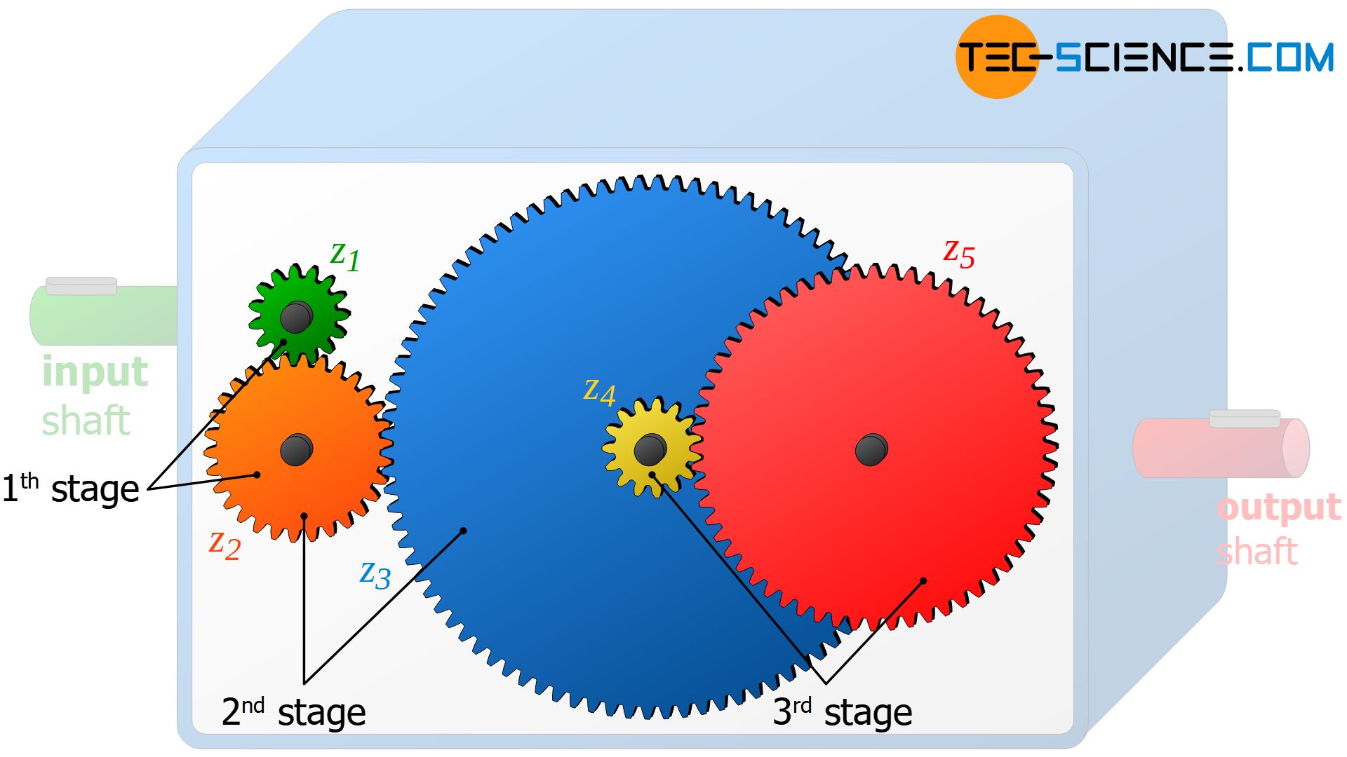
A gear stage is characterized by a change in speed and torque between the driving wheel and the driven wheel. The gearbox shown above consists of three gear stages, whereby each gear stage can be assigned a specific transmission ratio. The transmission ratio is defined as the ratio of the rotational speeds between the driving wheel (n1) and the driven wheel (n2):
\begin{align}
\label{def_uebersetzungsverhaeltnis}
&\boxed{i = \frac{n_1}{n_2}} \\[5px]
\end{align}
A gear stage is a wheel pairing within a gearbox at which the speed and torque changes!
The first gear stage is represented by the green gear (z1 = 15) and the orange gear (z2 = 30). The second gear stage results from the gear pairing of the orange gear wheel (z2) and the blue gear wheel (z3 = 90). The green gear (z4 = 15) and the red gear (z5 = 60) form the third gear stage. For the different gear stages this results in the following transmission ratios i:
\begin{align}
\label{1}
&\text{1. gear stage:}~~~ \underline{i_1} = \frac{z_2}{z_1} = \frac{30}{15} = \underline{2} \\[5px]
\label{2}
&\text{2. gear stage:}~~~ \underline{i_2} = \frac{z_3}{z_2} = \frac{90}{30} = \underline{3} \\[5px]
\label{3}
&\text{3. gear stage:}~~~ \underline{i_3} = \frac{z_5}{z_4} = \frac{60}{15} = \underline{4} \\[5px]
\end{align}
Note that gearwheels 3 and 4 do not represent a gear stage, since the gears are on a common shaft. The speed of the two gears is therefore identical. Thus neither a change of the speed nor a change of the torque takes place. Therefore, this gear pair is not a gear stage.
Overall transmission ratio
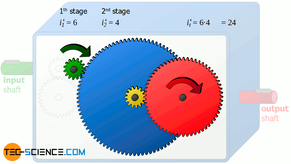
The torque increases as the speed decreases from stage to stage according to the transmission ratios calculated above. In the first gear stage, the torque of the gearbox input shaft is doubled. In the second gear stage, this doubled torque is now tripled. As a result, the torque after the second stage is 6 times higher than at the input shaft. Finally, in the third gear stage this 6 times greater torque is now quadrupled. The total torque at the output shaft of the gearbox is 24 times higher than the torque applied to the gearbox input shaft!
The reverse relationship applies to the speeds. This means, that the rotational speed between input and output of the gearbox is reduced by a factor of 24. Consequently, the input shaft must rotate 24 times for one revolution of the output shaft.
If only the gearbox input and the gearbox output are compared, then the entire transmission behaves like a single gear stage with a transmission ratio of 24. As this example shows, the total transmission ratio it of the entire gearbox can therefore be determined by multiplying the individual transmission ratios of the respective gear stages:
\begin{align}
\label{4}
&\boxed{i_t = i_1 \cdot i_2 \cdot i_3 \cdot \dots} \\[5px]
\end{align}
The overall transmission ratio of a gearbox results from the multiplication of the individual transmission ratios of the respective gear stages!
Since the transmission ratio of a gear stage depends on the ratio of the number of teeth involved, a change in the number of teeth on one of the gears generally results in a change of the overall transmission ratio.
If, for example, gear 5 (z5 = 60 teeth) is replaced by a gear wheel twice as large with twice the number of teeth (z5‘= 120 teeth), the gear ratio is doubled in this gear stage to i3‘= 8. This doubling also doubles the overall transmission ratio from 24 to it‘= 48.
Note that by multiplying the individual transmission ratios, each gear stage influences the total transmission ratio linearly according to equation (\ref{4}). Doubling or tripling a single gear stage therefore also means doubling or tripling the overall transmission ratio.
Pro and cons
The total transmission ratio of 24 obtained in this example could also be achieved with only one gear stage. In such a case, the gear wheel on the output shaft would have to be 24 times the size of the gear wheel on the input shaft. However, the dimensions of the gearbox would be very large.
The figure below shows the true-to-scale dimension of a single-stage gearbox with the same overall transmission ratio as the 3-stage gearbox.
Multi-stage gearboxes offer the advantage of dividing the desired transmission ratio into several smaller gear stages, thus keeping the overall dimensions of the gearbox small.
However, it must be noted that the friction increases with each gear stage. This is partly due to the fact that a total of more teeth mesh with each other, which generally slide against each other and thus also generate more friction. On the other hand, the respective shafts of the gear stages have to be mounted and thus cause increased bearing friction.
Influence of the number of teeth
It has already been explained that changing the number of teeth of a gear has a direct effect on the transmission ratio of the corresponding gear stage and generally also affects the overall transmission ratio.
In the case of gear wheel 2, however, a change in the number of teeth has no effect on the overall transmission ratio! This can be seen immediately if you take a closer look at the formula for determining the overall transmission ratio. For this, equation (\ref{1}), (\ref{2}) and (\ref{3}) are used directly in equation (\ref{4}). It becomes apparent that the number of teeth z2 cancel each other out. Thus the overall transmission ratio is obviously not dependent on the number of teeth z2:
\begin{align}
&\underline{i_{ges}} = i_1 \cdot i_2 \cdot i_3 = \frac{z_2}{z_1} \cdot \frac{z_3}{z_2} \cdot \frac{z_5}{z_4} = \underline{\frac{z_3 \cdot z_5}{z_1 \cdot z_4}} \\[5px]
\end{align}
But if the total transmission ratio does not depend on this gearwheel, what is its purpose? In fact, this gearwheel 2 can be dispensed with completely and thus gear 1 can mesh directly with gear 3 without any change in the overall transmission ratio of 24! A recalculation of the now 2-stage gearbox proofs it:
\begin{align}
\text{1. gear stage:}~~~ \underline{i_1} &= \frac{z_3}{z_1} = \frac{90}{15} = \underline{6} \\[5px]
\text{2. gear stage:}~~~ \underline{i_2} &= \frac{z_5}{z_4} = \frac{60}{15} = \underline{4} \\[5px]
\text{overall transmission ratio:}~~~ \underline{i_{ges}} &= i_1 \cdot i_2 = 6 \cdot 4 = \underline{24} \\[5px]
\end{align}
The fact that the total transmission ratio is independent of the number of teeth z2 can also be descriptively explained. If the gear wheel 1 of the drive shaft moves one tooth further, the gear wheel 2 also moves one tooth further. This movement of one tooth is now directly transferred from gearwheel 2 to gearwheel 3. In this respect, gearwheel 2 merely serves as a intermediate gear for pushing on the following gear. Thus gear 1 could also push the gear 3 directly one tooth further without changing anything in the basic process.
Depending on the function of the gearbox, however, gearwheel 2 is by no means superfluous. Because without it the output shaft rotates against its original direction of rotation! The intermediate gearwheel 2 serves as a so-called idler gear and thus has the function of adjusting the sense of rotation of the output shaft (reversal of the direction of rotation). In order to fulfill this task, the idler gear 2 could in principle also be placed between gearwheel 4 and 5.
An idler gear reverses the direction of rotation without affecting the overall transmission ratio!
Arrangement of the gears
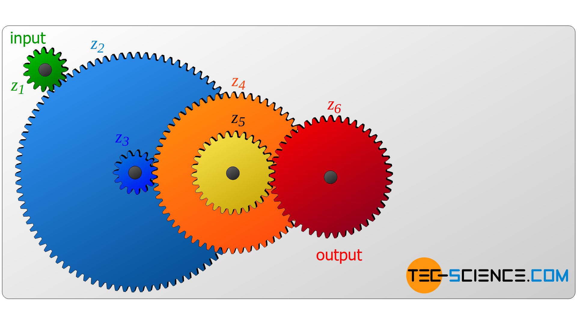
Under what condition does the number of teeth of a gear wheel influence the overall transmission ratio and when not? The figure below shows a gear train in which gears are mounted on separate shafts. In such a case, the total transmission ratio depends only on the number of teeth of the first gear (z1) and the last gear (z6):
\begin{align}
\require{cancel}
&\underline{i_{t}} = i_1 \cdot i_2 \cdot i_3 \cdot i_4 \cdot i_5 = \frac{\bcancel{z_2}}{z_1} \cdot \frac{\bcancel{z_3}}{\bcancel{z_2}} \cdot \frac{\bcancel{z_4}}{\bcancel{z_3}} \cdot \frac{\bcancel{z_5}}{\bcancel{z_4}} \cdot \frac{z_6}{\bcancel{z_5}} = \underline{\frac{z_6}{z_1}} \\[5px]
\end{align}
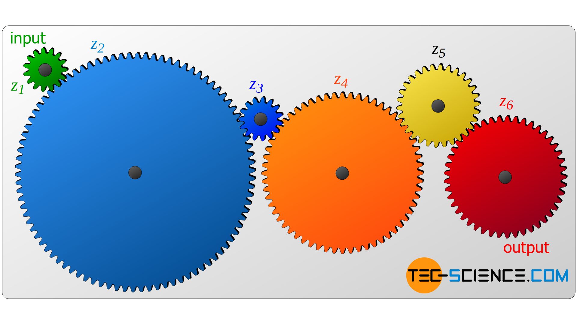
In order to design transmissions effectively, two different gears must always be arranged on a common shaft, which in turn drives a shaft with another pair of gears. In this case, the number of teeth of all gears is then included in the calculation of the overall transmission ratio!
\begin{align}
\require{cancel}
&\underline{i_{t}} = i_1 \cdot i_2 \cdot i_3 = \underline{ \frac{z_2}{z_1} \cdot \frac{z_4}{z_3} \cdot \frac{z_6}{z_5}} \\[5px]
\end{align}
 are there?")
 and what is it used for?")
")

 work?")