During the deformation of single crystals, slip steps preferably form at 45° to the tensile axis, since the shear stresses are at a maximum.
Introduction
If a material on the atomic level is characterized by a uniform lattice orientation (no grain boundaries), it is also called a single crystal.
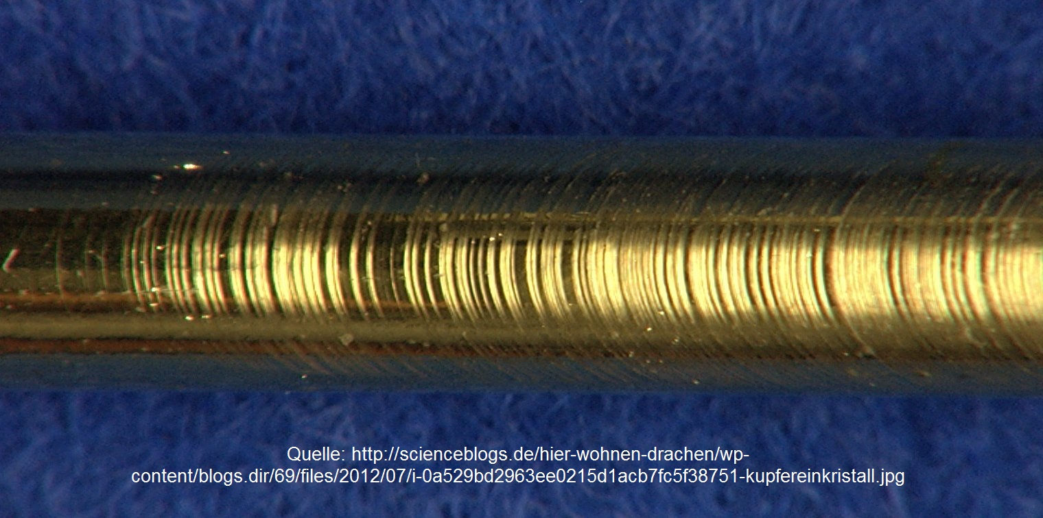
If such a single crystal is deformed under tension, inclined rings are formed in the deformation region. This can be clearly seen from the copper single crystal shown in the figure below. These rings are so-called slip steps.
Why these slip steps preferentially aligned at an angle of 45°, will be clarified in the following sections.
Shear force
The single crystal with a cross-sectional area A0is externally loaded with the tensile force F0. In order to initiate the deformation process and to allow the atomic planes to shear off, a force F|| must act in the slip planes. Only in this way can the plane actually be moved in the slip direction. On the other hand, a normal force acting perpendicular to the slip planes has no influence on the deformation. As a result, the layers would merely be compressed but not moved.
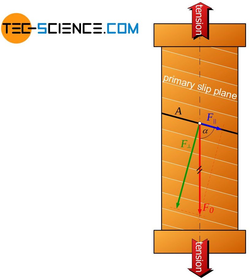
If a slip plane lies at an angle \(\alpha\) to the tensile axis, then the external force F0 can be resloved into a parallel component (shear force F||) and a perpendicular component (normal force F⊥) to the slip plane. Mathematically, the shear force and the normal force can be determined as a function of the angle \(\alpha\) as follows:
\begin{align}
\label{kraft}
F_{\parallel}&=F_0 \cdot \cos(\alpha) ~~~~~\text{shear force} \\[5px]
F_{\perp}&=F_0 \cdot \sin(\alpha)~~~~~\text{normal force} \\[5px]
\end{align}
If the angle \(\alpha\) between the surface normal and the tensile axis is relatively small, the shear force in the slip plane is also relatively low. The force may not be sufficient to activate the slip plane and initiate the deformation process.
If, on the other hand, the slip plane normal lies at a relatively large angle (\alpha\) to the tensile axis, the shear force in the slip plane is relatively large at first. However, at the same time the slip plane area and with it the binding force between the planes increases. Even in this case, the greater shear force may still not be enough to shear off the plane and start the deformation process.
The situation can be compared with a hook-and-loop fastener, wherein the mutual entanglements between the closure materials correspond to the bonds between the atomic planes. If the shear forces to open the hook-and-loop fastener are too low, the closure materials do not slide off each other. However, a multiplication of the force does not lead to slippage, if at the same time the overlap area of the two closure materials increases disproportionately.
There must therefore be a favorable ratio of force and area in order to reach the optimum state where most force per area is obtained. That means where the greatest shear stress is achieved.
Shear stress
Decisive for a slipping of the atomic planes is therefore not the force in the slip plane alone but the acting force per area, i.e. the shear stress (see also fundamentals of deformation):
\begin{equation}
\label{schubspannung}
\tau=\frac{F_{\parallel}}{A}
\end{equation}
While the force F|| depends on the angle \(\alpha\) of the slip plane accordingly to the equation (\ref{kraft}), the slip plane area A is determined as follows by the sample’s cross section F0:
\begin{equation}
\label{flaeche}
A=\frac{A_0}{\sin(\alpha)}
\end{equation}
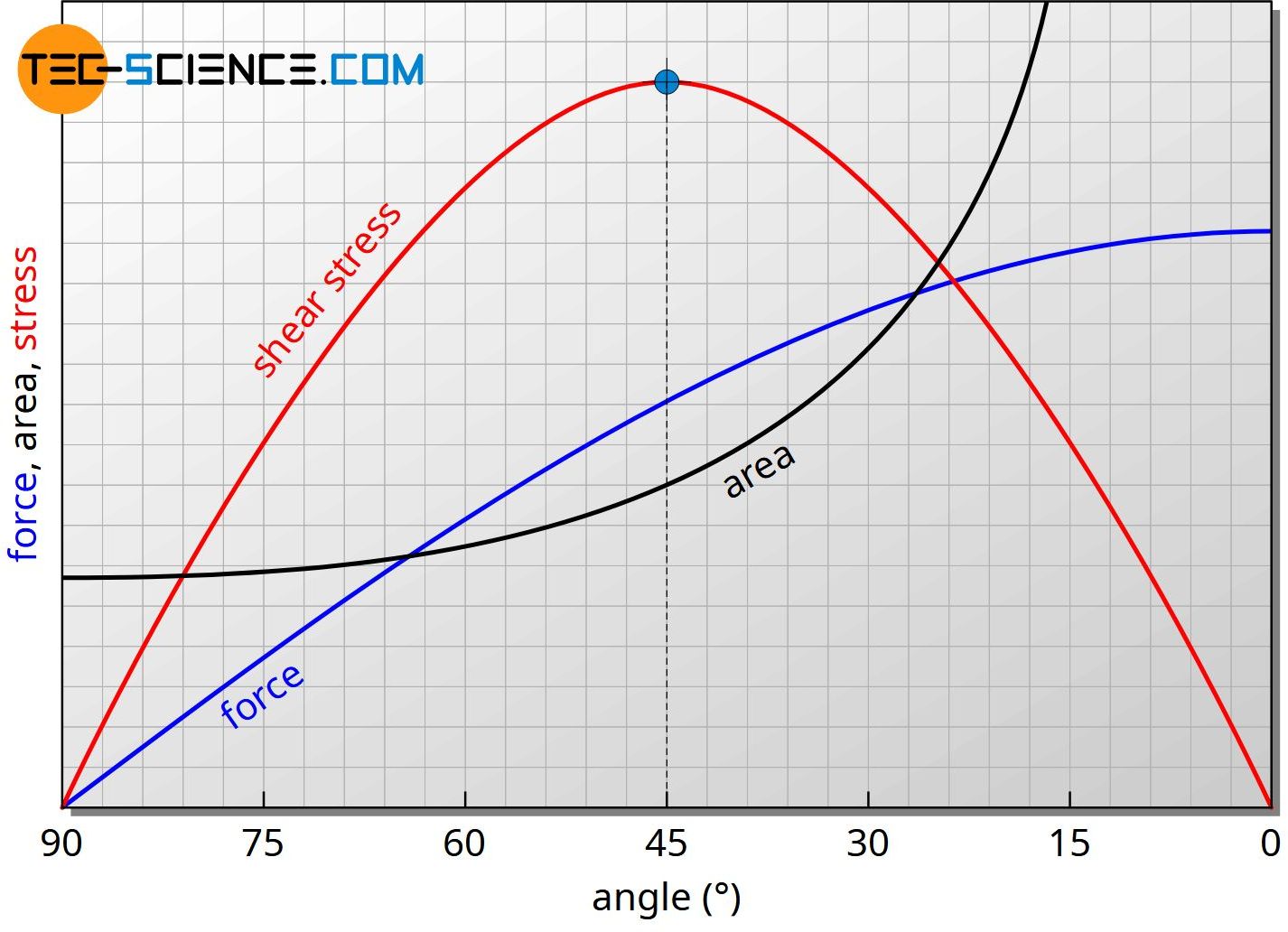
The increase of the shear force (blue curve) and the increase of the area (black curve) with increasing angle schematically shows the diagram below. In addition, the resulting curve of the shear stress is shown (red curve). Obviously, the largest force per area acts at an angle of 45°. This will be shown mathematically in the following section.
Maximum shear stress
The shear stress curve shown in the figure above is obtained by inserting the equation (\ref{kraft}) and the equation (\ref{flaeche}) in the shear stress equation (\ref{schubspannung}):
\begin{equation}
\label{scherspannung}
\tau=\frac{F_{\parallel}}{A}=\frac{F_0 \cdot \cos(\alpha)}{\frac{A_0}{\sin(\alpha)}} =\frac{F_0}{A_0} \cdot \cos(\alpha) \cdot \sin(\alpha)
\end{equation}
The quotient \(\frac{F_0}{A_0}\) appearing in equation (\ref{scherspannung}) corresponds to the normal stress \(\sigma_0\) applied from the outside (“force per cross-sectional area”). For the angle-dependent shear stress \(\tau(\alpha)\), therefore, the following equation applies:
\begin{equation}
\tau(\alpha)=\sigma_0 \cdot \cos(\alpha) \cdot \sin(\alpha)
\end{equation}
The term \(\cos(\alpha)\cdot \sin(\alpha)\) can further be replaced by the expression \(\frac{\sin(2\alpha)}{2}\). Thus, the effective shear stress \(\tau\) in a slip plane which is aligned at the angle \(\alpha\) to the tensile axis, can be calculated as follows:
\begin{equation}
\label{tau}
\boxed{\tau(\alpha)={\frac{\sin(2 \alpha)}{2} \cdot \sigma_0} }
\end{equation}
The internal shear stress \(\tau\) thus depends on the applied external stress \(\sigma_0\) and in particular on the angular position \(\alpha\). The term \(\sin(2 \alpha)\) reaches the maximum value 1 for an angle of \(\alpha\) = 45°.
It is now also shown mathematically that the maximum shear stress \(\tau_ {max}\) is thus reached at an angle of \(\alpha\) = 45°. For this case, the maximum shear stress corresponds to exactly half of the outer normal stresses \(\sigma_0\)!
\begin{equation}
\label{max}
\boxed{\tau_{max}=\frac{\sigma_0}{2}} ~~~ \text{for} ~~~ \alpha=45°
\end{equation}
External normal stresses induce shear stresses in the material interior, which become maximum at an angle of 45°. In those favorably lying slip planes, the atomic layers therefore prefer to shear off!
This is the reason why the copper single crystal shown above has slip steps at an angle of about 45° to the tensile axis. The prerequisite for this is that the lattice structure is spatially oriented in such a way that a slip plane is aligned at an angle of about 45°. The effects of the deformation process when the slip plane is not at 45 ° will be discussed in the next section.
Note: In addition to the optimal orientation of the slip plane, the slip direction must also be oriented accordingly. This optimal orientation has been assumed tacitly. The article Schmid’s law deals with this topic in more detail.
Influence of lattice orientation
What does the deformation of a single crystal look like if its slip planes are not at an angle of 45°? Due to the less favorable position, larger external normal stresses are required in this case, so that the critical resolved shear stress in the slip plane (and in the slip direction!) will be exceeded.
Multiple gliding
In the case of a very unfavorable position of the (primary) slip planes, this can even lead to an activation of other slip planes, which normally only come into account at higher stresses, because in them the critical shear stress is exceeded first. Slipping then probably takes place in several different slip systems.
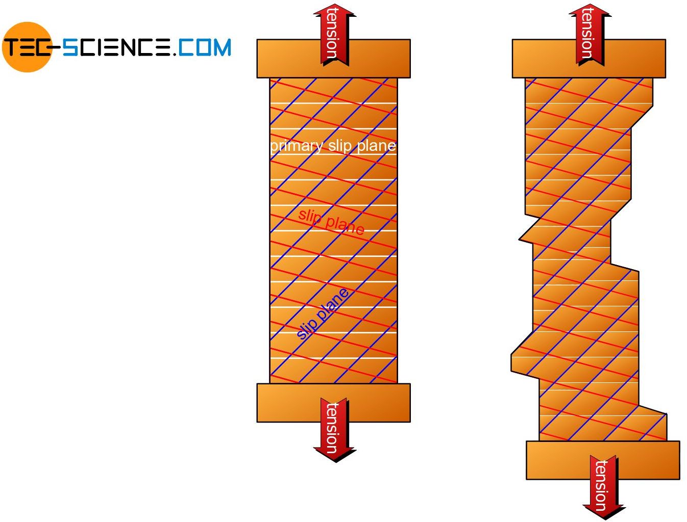
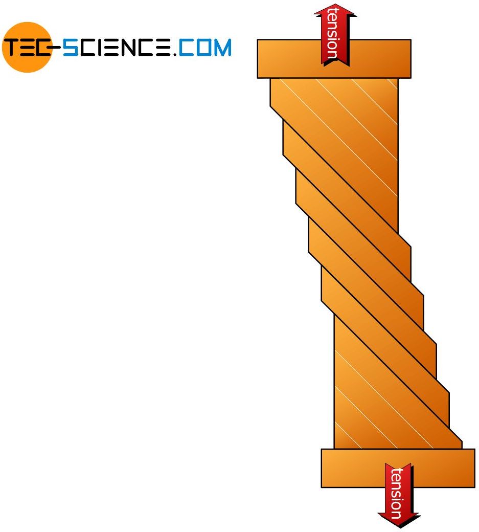
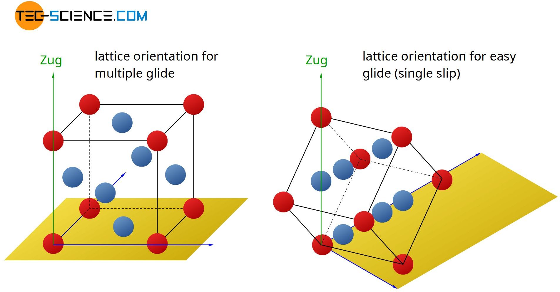
This will be the case if the different slip planes are relatively symmetrical arranged to the tensile axis. Then the critical shear stress in all slip systems is reached approximately simultaneously. For face-centered cubic monocrystals, the unit cells must be aligned nearly parallel to the tensile axis (see figure after next).
All four slip planes are then activated equally. Due to the fact that the shearing takes place on several different slip planes, one also speaks of multiple gliding. By such multiple gliding, the crystal is then deformed in different directions. The slip steps exit the material at different angles and spatial directions. The superposition of these slip steps makes it impossible to distingish different slip steps from one another. Therefore they are not visible with the naked eye.
Figure: Multiple gliding in a single crystal
Easy gliding
On the other hand, in the image of the copper single crystal obviously shows distinguished uniform slip steps. The reason for this is that the fcc lattice was specially aligned to the tensile axis. The single crystal was so designed that only one slip plane was oriented at an angle of approximately 45° to the tensile axis.
Thus, upon reaching the limit stress, only this slip plane was activated, while the shear stresses in the remaining slip planes (or in the slip direction) remained below the critical resolved shear stress. Since in such a case, the sliding takes place only within one slip plane, this process is also referred to as a single gliding or easy gliding.
The external normal stress that has to be applied \(\sigma_{crit}\) to a material in order to exceed the critical resolved shear stress in a slip plane, is referred to as yield strength or elastic limit.
This characteristic value thus refers to the (tensile) stress at which an irreversible deformation process begins. As explained, the yield strength for single crystals depends on the spatial orientation of the lattice! The lowest value of the yield strength is therefore obtained for single crystals when their slip planes are aligned at an angle of 45 ° to the tensile axis.
The yield strength marks the stress limit from which on a material deforms plastically!
Polycrystals
The annular depiction of the slip steps at an angle of 45° is only evident in specially oriented single crystals. However, single crystals can only be produced with great technical effort. They are therefore limited to special applications such as nickel-based single-crystal turbine blades or silicon chip production.
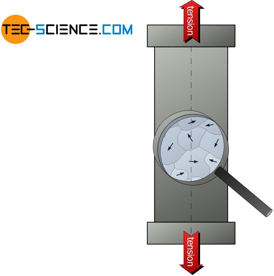
In general metals do not have a uniform lattice orientation (note: the term lattice orientation must not be confused with the term lattice structure!). Rather, many small microscopic areas (grains) are found in a metal, each with a different lattice orientation. Such crystals are also referred to as polycrystals.
Thus, in such polycrystals several slip systems with different slip plane orientation are always simultaneously activated (multiple gliding). A uniform exit of slip steps is therefore not visible in such materials anyway. How it comes to such a nonuniform lattice orientation is explained in more detail in the chapter microstructure.
In this article, only the processes that lead to the initiation of a deformation were discussed. The actual deformation process in single crystals is therefore discussed in more detail in the article deformation process in single crystals.


