Learn more about the design, function and application of a differential gear and the differential lock in this article.
Why does a car need a differential gear?
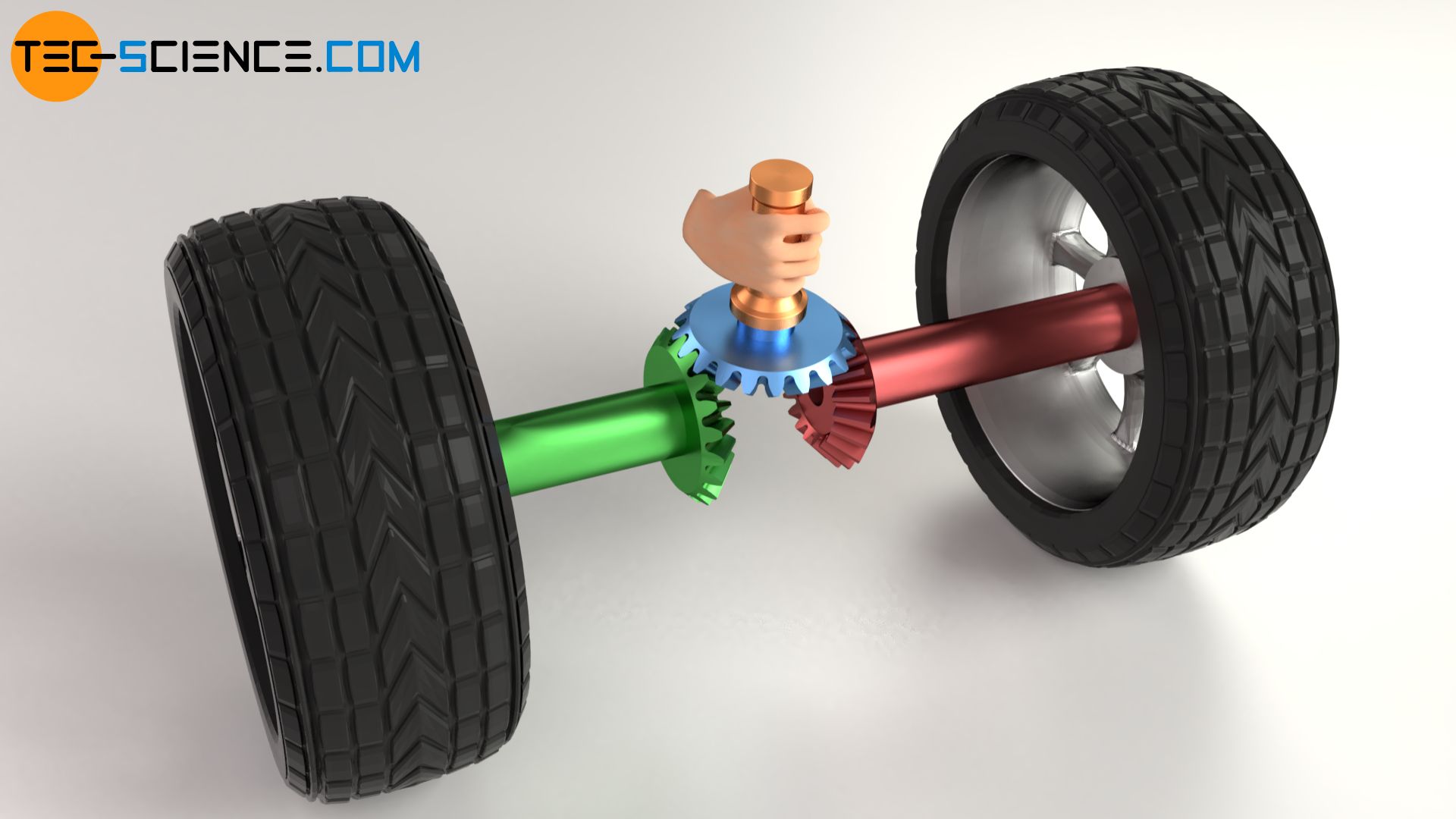
In automobiles, the wheels are usually driven by the engine using a bevel gear. This allows the rotational motion from the engine to the wheels to be deflected by 90°. If, however, the wheels were rigidly connected to each other by a common shaft, this would lead to problems when cornering. In such a case, the outer wheel must cover a greater distance than the inner wheel. However, since both wheels must travel around the turn at the same time, the outer wheel must rotate faster than the inner wheel.
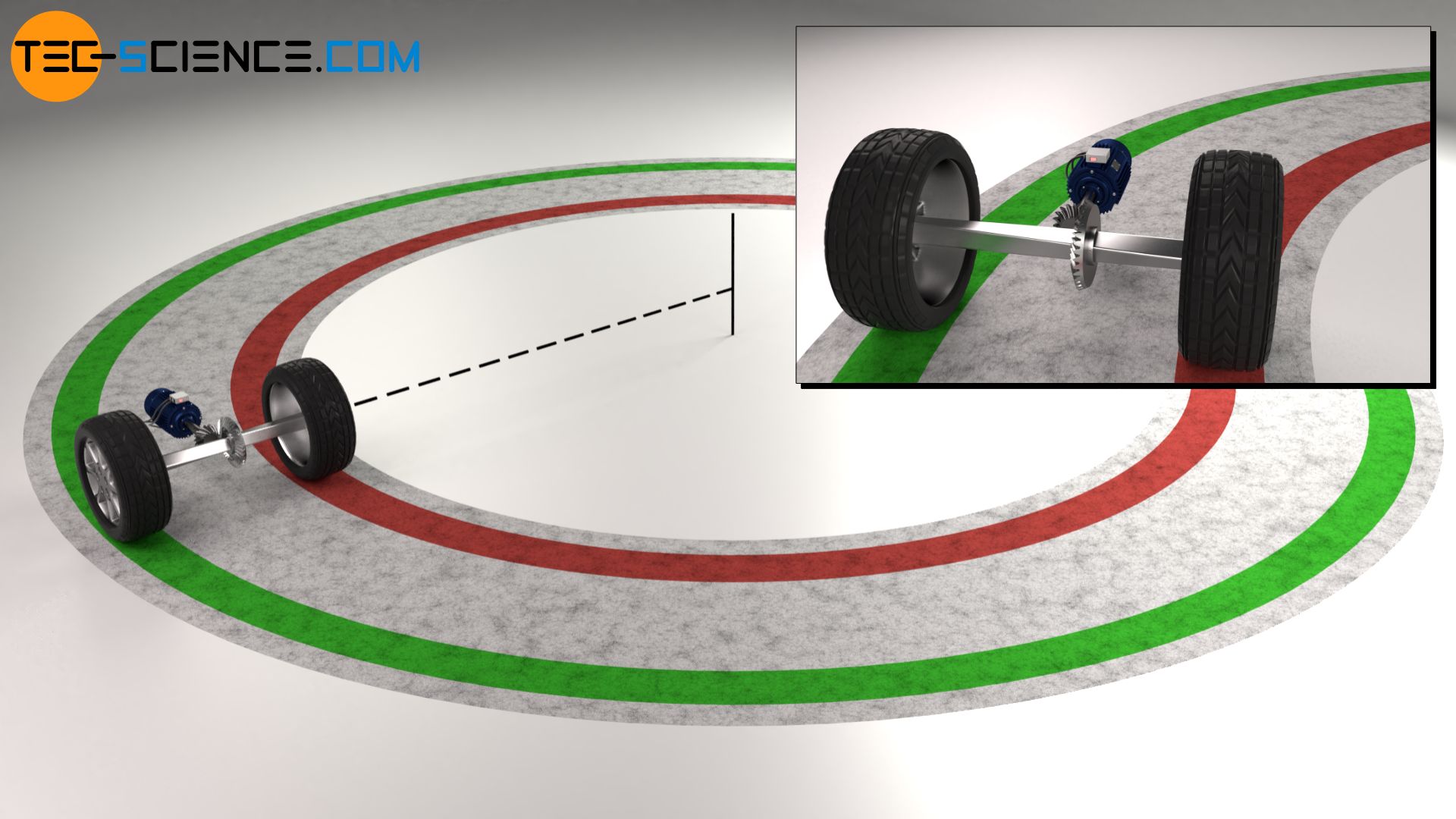
If the two wheels would be connected by a common shaft, the shaft would twist due to the different rotational speeds. Sooner or later, such a twist is compensated by a slipping of one of the wheels. This slipping in the curve not only reduces driving safety but also leads to considerable tyre wear and, in the long run, to shaft breakage.
When cornering, the outer wheel must be able to rotate faster than the inner wheel!
For this reason, in the early days, only one of the wheels was driven. The other wheel was mounted freely on the shaft so that it could rotate with a different speed. Such a one-sided drive leads however to the fact that the vehicle tries to drive a slight curve. This reduces not only the driving fun but also the driving safety. It was therefore necessary to find a solution to drive both wheels at the same time while allowing different speeds: The differential gear was born.
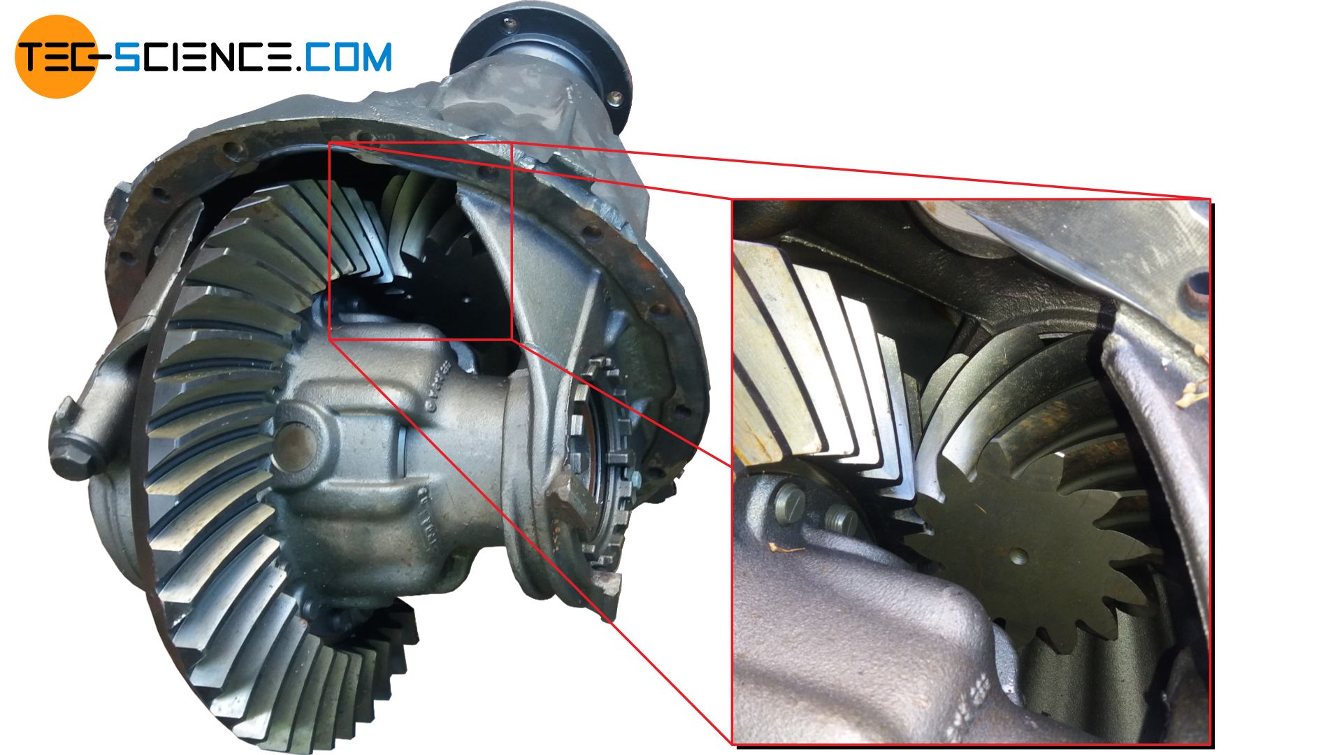
The picture below shows the differential gear of a truck. One sees the pinion (shown yellow in the animation above) and the bevel gear (shown orange in the animation above). The other bevel gears are inside the housing and not visible from the outside.
Design of a differential gear
The design and operating principle of a differential gear are not easy to understand at first glance. The main question is how to come up with such an arrangement of gears. For the sake of simplicity, it makes sense to first understand the individual steps behind the idea of the differential gear.
1st step – drive of the separated shafts by pins and a freely rotatable bar
The initial idea is to first divide the common drive shaft so that each wheel has its own drive shaft. This ensures that the shaft does not twist if one of the two wheels rotates with a different speed. Two pins are now attached to each of the separate shafts. Between these pins, a freely rotatable bar drives the respective wheel shafts.
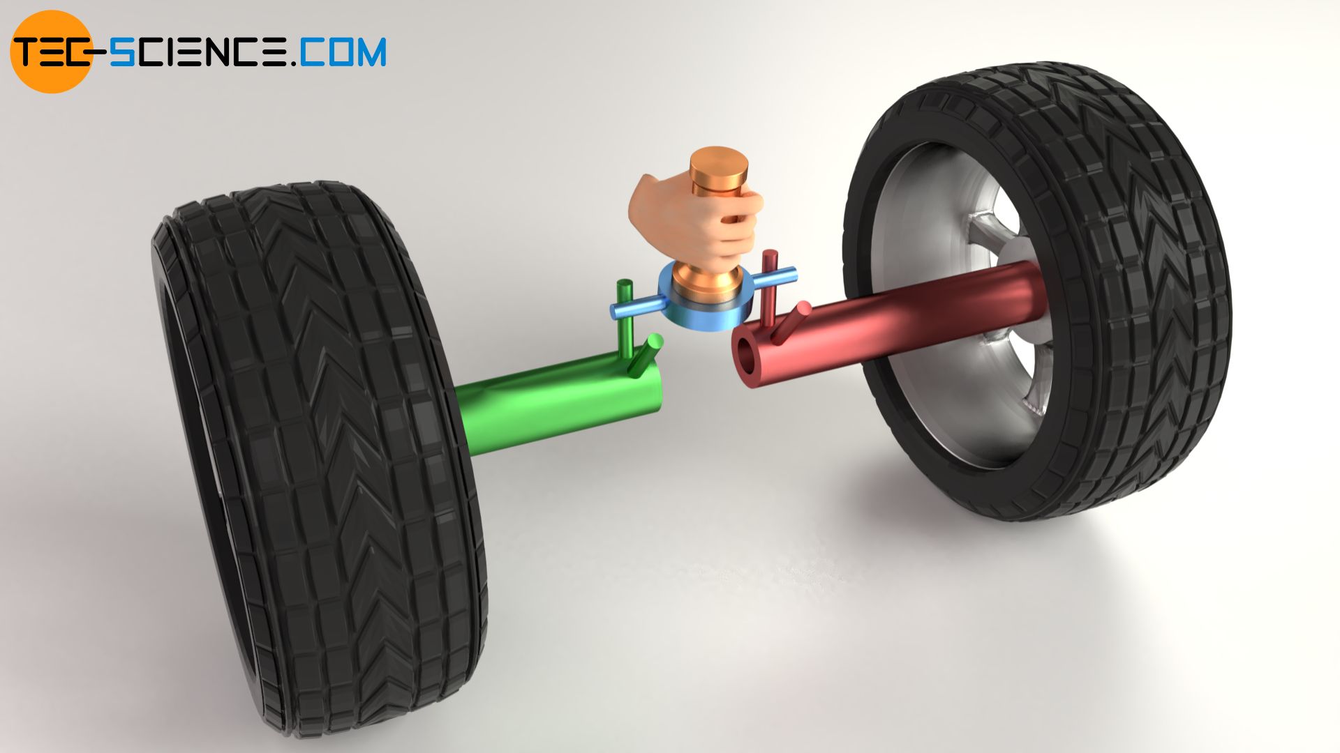
In this way, the wheels can be rotated to different degrees within a certain limit. If one of the wheels is slowed down, the opposite wheel can be moved a little further by the rotatable bar. However, the different rotation should not be too large, otherwise the rod will slide out of the pins and no more force can be transmitted.
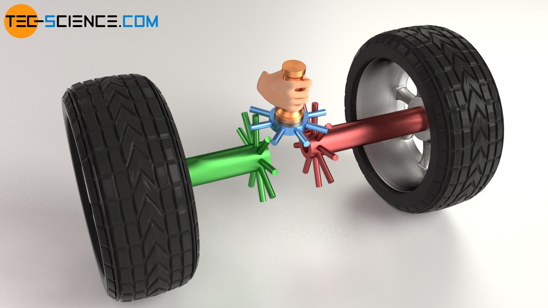
2nd step – drive of the shafts by several pins and freely rotatable bars
In order to increase the yet very limited motion, one could just use several pins instead of only one as well as more rotatable bars. The pins and the bars can now slide into each other one after the other. The wheel drive is no longer limited. One of the wheels can now rotate at a completely different speed and even stand still, while the other wheel can continue to be driven. In principle, such an arrangement already represents a fully functional differential gear!
A closer look shows that with such a differential, the slowed wheel is decelerated to the same extent as the other wheel is accelerated. The speed loss on one side of the wheel is compensated by a speed gain of the same magnitude on the other side. This principle is based on the law of conservation of energy.
Such a kinematic behaviour of the wheels is exactly what is needed when cornering. When cornering, the inner wheel must rotate more slowly to the same extent as the outer wheel must rotate faster.
A differential gear ensures that the inner wheel rotates to the same extent more slowly as the outer wheel rotates faster when cornering!
3rd step – Replacing pins and bars with bevel gears
The power transmission by pins and bars is not very effective. Therefore they are replaced by gears, more precisely by bevel gears. The bevel gear shown in blue, which revolves around the shafts of the wheels, is also referred to as the spider gear. In principle, this spider gear is nothing else than a planet gear as it is known from planetary gears. And indeed, the differential gear can be seen as a special form of a planetary gearbox (more on this later).
4th step – drive of the shafts by further bevel gears
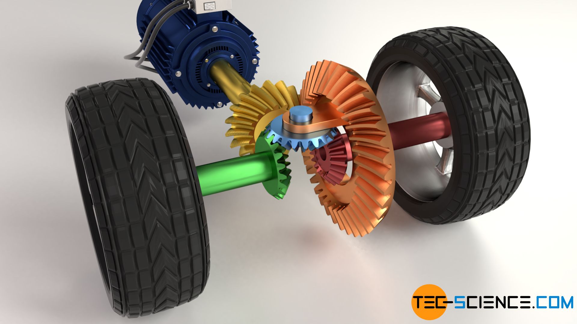
The drive of the spider gear is of course not done by hand but by the engine. The spider gear is in turn driven by a bevel gear unit (usually a hypoid gear), consisting of a pinion (shown in yellow) and a bevel gear (shown in orange). The spider gear ist mounted on this orange bevel gear. Since the orange bevel gear “carries” the revolving spider gear, the orange bevel gear is also referred to as carrier.
5th step – symmetrical arrangement of the bevel gears to avoid bending stresses
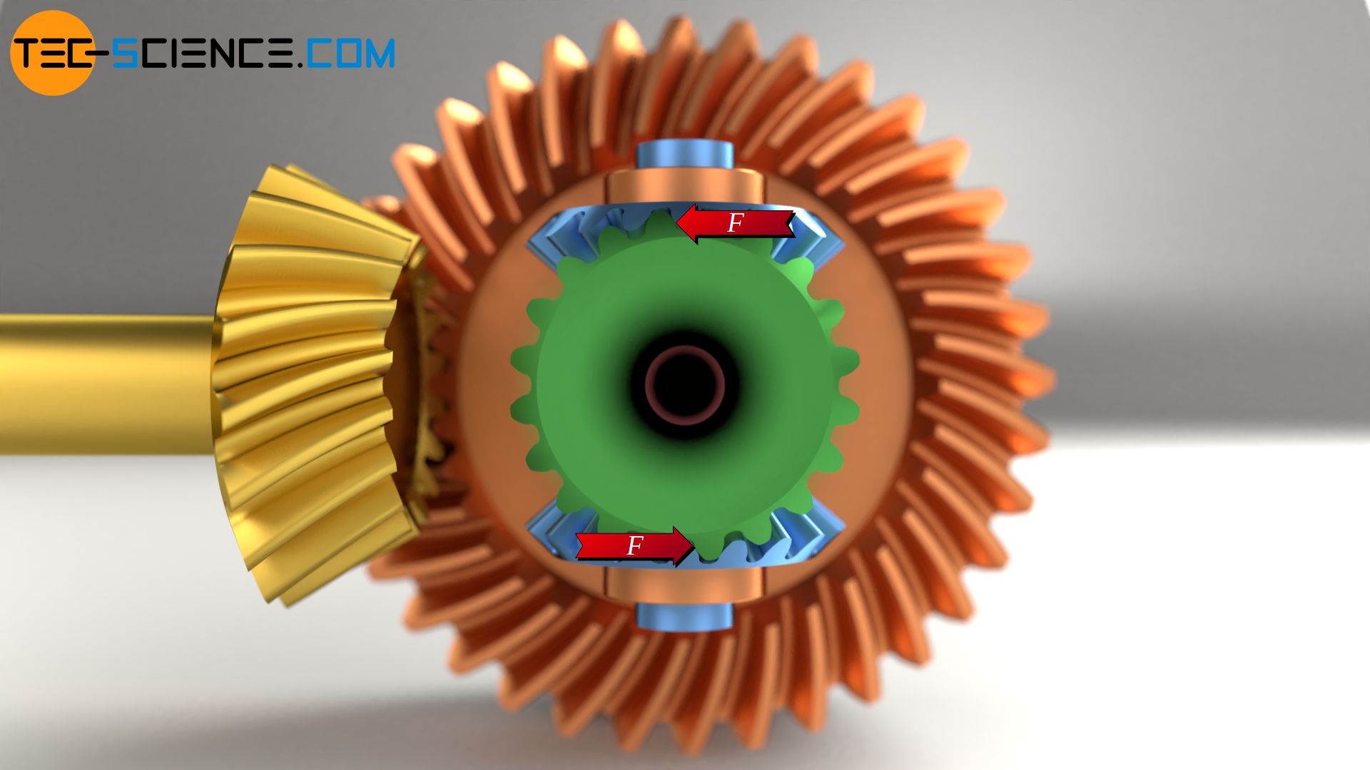
In order to avoid bending stresses in the drive shafts of the wheels, they are usually not driven by only one spider gear but by two spider gears. The second spider gear is offset by 180°.
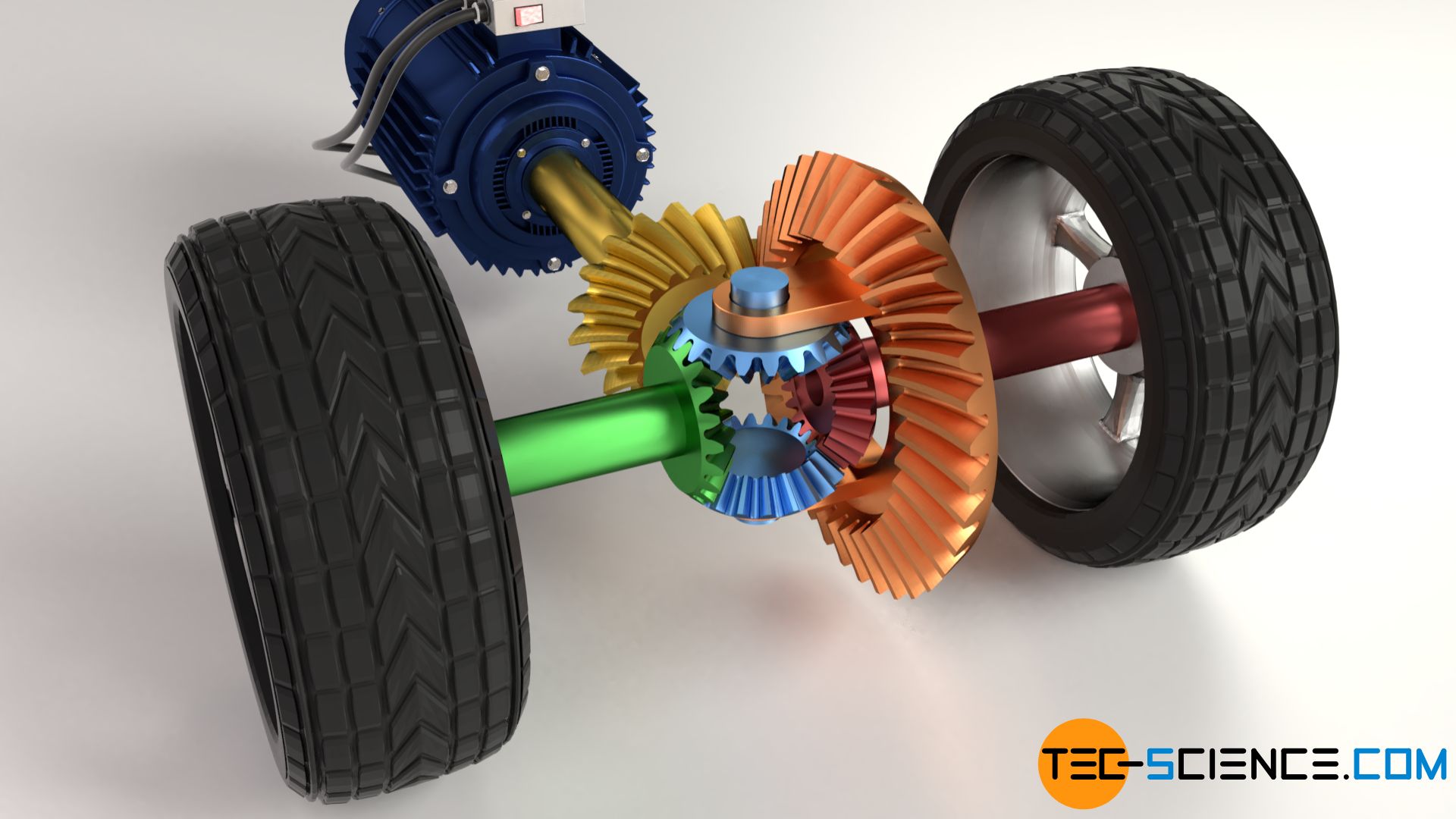
The figure below shows that when using two spider gears, the forces compensate each other in the horizontal direction. The drive shafts of the wheels are then subjected purely to torsion, but not to bending!
Kinematics of a differential gear
When driving straight ahead, normally none of the wheels is forced to rotate slower or faster than the other. In this case, the spider gears drive the wheel shafts without any relative motion. The wheels then rotate at the same speed as the carrier.
If one now drives into a right turn, for example, the inner wheel is slowed down by the shorter distance to be travelled. However, the outer wheel must then rotate faster to the same extent, since it has to cover a greater distance. Due to its special design, a differential gear ultimately ensures exactly such a kinematic behavior! The exact mathematical relationship is explained in more detail in the next section.
The best way to understand the kinematics is to imagine an extreme cornering where the inner wheel practically stands still and the outer wheel follows a circular path around the inner wheel. In this case, the carrier drives the spider gears around the bevel gear (“side gear”) of the stationary wheel shaft. The spider gears then begin to rotate and now perform relative motions. The opposite bevel gear (“side gear”) of the left drive shaft is now driven by this rotation of the spider gears in addition to the already existing rotation of the carrier and thus rotates faster.
Compared to the carrier, the inner wheel rotates more slowly to the same extent as the outer wheel rotates faster when cornering.
Only when cornering is complete and the wheel speeds have been adjusted again, do the two wheel shafts no longer move relative to each other and the speed of the carrier corresponds to the wheel speeds.
Even if the speeds of the wheels differ when cornering, both wheels are always driven by the same torque! This is because in gearboxes the change in torque only results from the ratio of the number of teeth of the gears. However, the differential gear has a symmetrical design. It does not differ in the number of teeth between the left and right drive shaft. This means that the change in toraue between the motor and the drive shafts are always the same. Both gears therefore have the same torque.
Even if the respective torque at the wheels does not differ, they have different powers! This is because the power is determined by the product of torque M and rotational speed n:
\begin{align}
\boxed{P=2 \pi \cdot M \cdot n} \\[5px]
\end{align}
It should be noted, however, that when the differential is active when cornering, there are relative motions of the bevel gears which lead to an additional reduction in gear efficiency.
Although a differential gear provides different speeds and thus different power for the wheels, the torque on both wheels is identical!
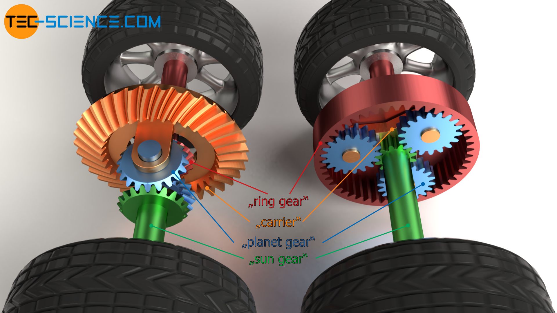
Differential gear as a special case of a planetary gearbox
As already mentioned, a differential gear is a special type of a planetary gearbox. One of the bevel gears on the wheel shafts can be regarded as a sun gear while the other bevel gear then corresponds in a figurative sense to the ring gear.
Since a differential is a special type of a planetary gearbox, the relationship between the different rotational speeds can also be described by the fundamental equation for planetary gears (Willis equation):
\begin{align}
&\boxed{ n_s = n_c \cdot \left(1-i_0 \right) + n_r \cdot i_0} \\[5px]
\end{align}
For classic planetary gears, nr refers to the rotational speed of the ring gear, ns denotes the rotational speed of the sun gear and nc refers to the rotational speed of the carrier. i0 denotes the so-called fixed carrier transmission ratio.
In the case of a differential gear, the fixed carrier transmission ratio corresponds to the transmission ratio which is obtained when the carrier is fixed. If one of the wheels (the “ring gear”) is rotated in this state, then the other wheel (the “sun gear”) obviously rotates at the same speed, but in the opposite direction. The fixed carrier transmission ratio is therefore i0=-1.
If the fixed carrier transmission ratio of i0=-1 is used in the upper equation, then the following relationships apply:
\begin{align}
& n_s = n_c \cdot \left(1-i_0 \right) + n_r \cdot i_0 ~~~\text{with}~i_0=-1~~~~\text{:} \\[5px]
&n_s = n_c \cdot \left(1-(-1) \right) + n_r \cdot (-1) \\[5px]
&n_s = n_c \cdot 2 – n_r \\[5px]
&n_r + n_s = 2 \cdot n_c \\[5px]
\end{align}
Since differential gears do not have a classic sun gear or ring gear, the corresponding rotational speeds of the gears are denoted by n1 (=nr) or n2 (=ns). Thus, the following relationship between the rotational speeds of the wheels n1 or n2 and the rotational speed of the carrier nc applies:
\begin{align}
&\boxed{n_1 + n_2 = 2 \cdot n_c} \\[5px]
\end{align}
The right side of the equation is always constant at a constant speed of the carrier and thus at a constant motor speed. Now it can also be seen mathematically that at a constant motor speed, a reduction of the speed at one of the wheels results in an increased speed at the opposite wheel. By rearranging the equation, one can also see that the speed of the carrier corresponds to the mean speed of the two wheels.
\begin{align}
&\boxed{n_c = \frac{n_1 + n_2}{2}} \\[5px]
\end{align}
Differential lock
The big advantage of differential gears is that they can be used when cornering by dividing the rotational speed or power between the respective wheels according to their needs. In some situations, however, this can also be a disadvantage. For example, when starting on a smooth or slippery ground, one of the wheels may lose its grip and slip, while the other wheel remains on the ground. The differential gear now transmits the entire power to the rotating wheel, while no power is at the stationary wheel. The spinning wheel now turns at double speed, while the other wheel stands still. In this way one hardly obtains a forward driving force and if then only a one-sided force due to the sliding friction of the rotating wheel.
Such a case where one of the wheels has less grip than the other and is thus tempted to slip, occurs primarily during off-road driving, where the load on the wheels varies permanently. But even in fast cornering, where the inner wheel is greatly relieved by the centrifugal forces, the danger of slipping increases and the one-sided power distribution threatens. If, in the worst case, the vehicle tilts slightly and the inner wheel loses its grip, this wheel receives full power and rotates in the air at twice the speed. The opposite wheel, which still has the grip to the ground, does not get any power and therefore no drive of the car is possible anymore.
In the cases mentioned above, a differential gear is therefore more of an obstacle. For this reason, mainly off-road vehicles are equipped with so-called differential locks. Such a differential lock then rigidly connects the two drive shafts of the wheels with each other again and thus deactivates the differential. However, this leads to the twisting of the drive shaft when cornering, as already explained at the beginning. Differential locks should therefore only be activated in exceptional cases.
")


")