The Willis equation describes the motion of the individual gears of a planetary gearbox (epicyclic gear).
Superposition of motions
The change in speed of planetary gearboxes are no longer as easy to understand as those of stationary transmissions. This is due to the fact that the motion of the rotating planet gears is ultimately a superposition of three different motions. The motion no longer consists of a simple rotation around its own axis, but the axis itself performs an additional circular motion around the axis of the sun gear, while the planet gear also performs an additional circular motion because of the rotation of the sun gear.

Thus, the motion of a rotating planet gear can be traced back to the superposition of three separately observable motions:
- rotation of the carrier around the sun gear
- rotation of the planet gear around its own center of gravity
- rotation of the sun gear
| 1 | 2 | 3 |
 Motion of the carrier |  Motion of the planet gear | Total motion |
However, the motions are not independent from each other, because the planet gear rotates on the sun gear. Thus the diameter ratio between the sun gear and the planet gear determines how often the planet gear rotates around its own axis while it moves once around the sun gear.
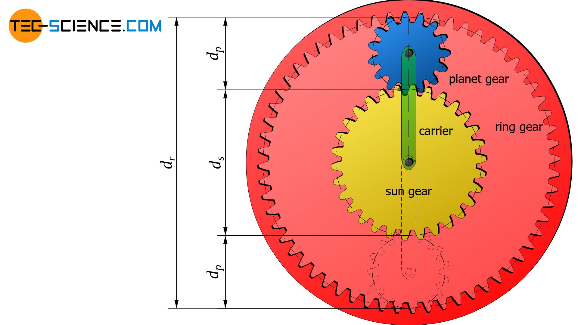
In order to derive the relationship of the rotational speeds between the sun gear, the planet gear and the carrier, the above-mentioned motions are first described separately and then superposed. For the sake of clarity, the gears are assumed to be (pitch) cylinders.
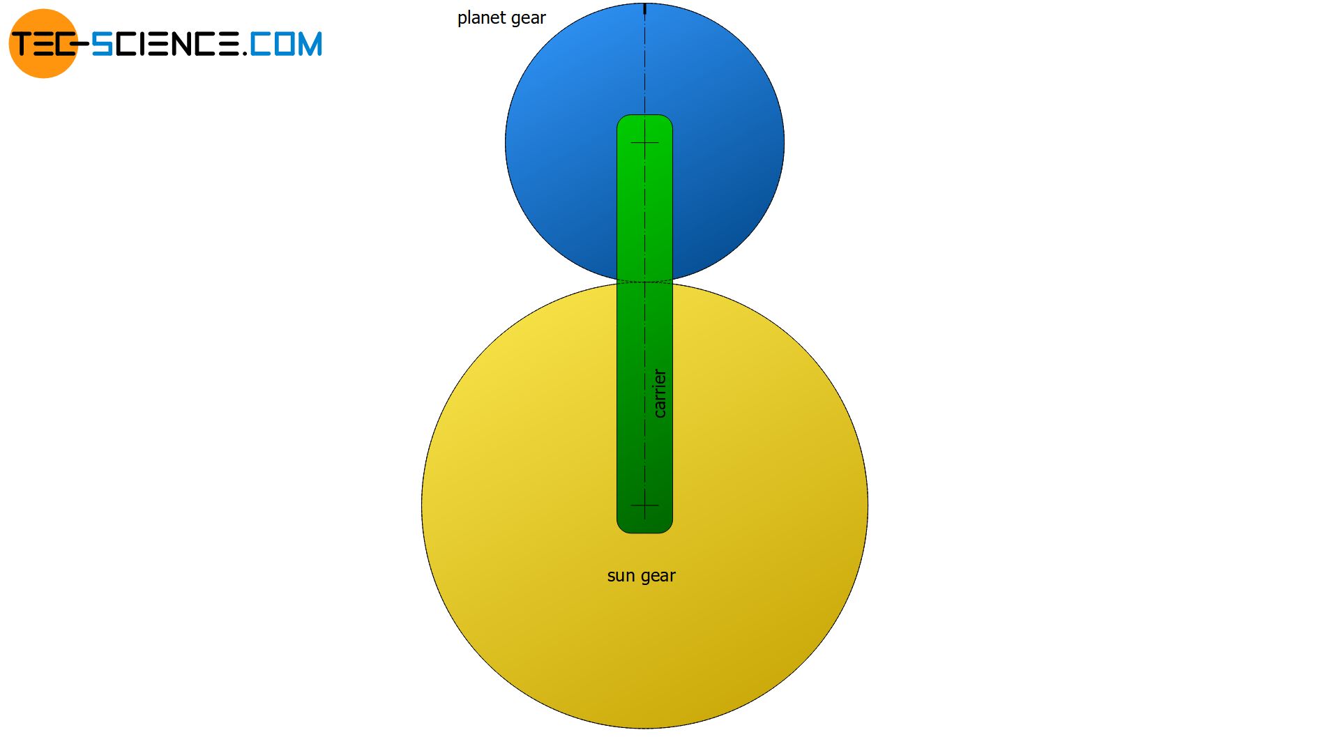
Rotation of the carrier around the sun gear
If the sun gear stands still and the planet gear is locked firm on the carrier, then the swept angle of the carrier φc corresponds to the angular position of the planet gear φp1.
\begin{align}
\label{P1}
&\underline{\varphi_{p1} = \varphi_c} \\[5px]
\end{align}

Rotation of the planet gear around its own center of gravity
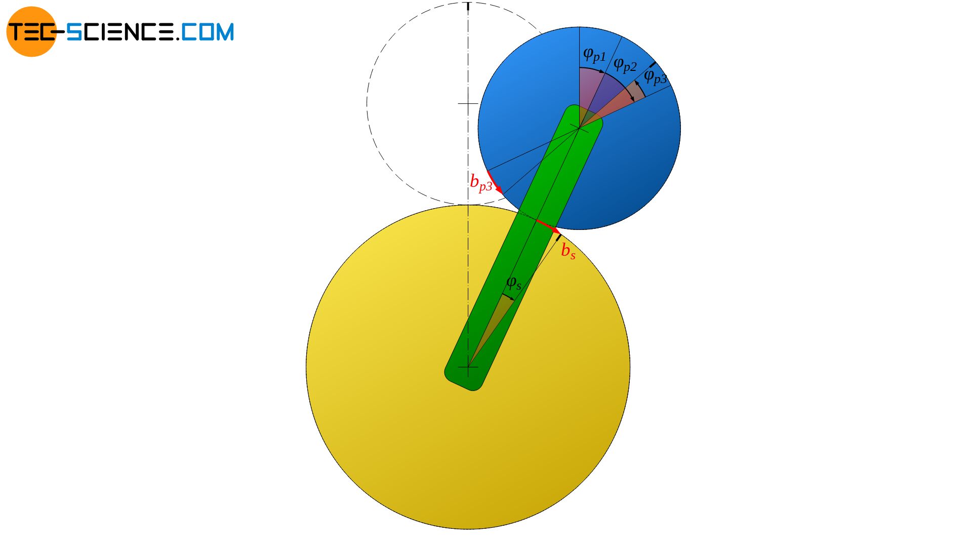
In fact, the planet gear will roll on the sun gear when mounted rotatably on the carrier and thus rotate around its own center of gravity. The planet gear will thus rotate by an additional angle φp2.
If one considers a mere rolling motion, then the arc length bc, which the carrier has covered on the sun gear, corresponds exactly to the arc length bp2, by which the planet gear has moved on its circumference. The additional angle φp2 can be determined by the radian measure as follows:
\begin{align}
&b_{p2} = b_c \\[5px]
&\tfrac{d_p}{2} \cdot \varphi_{p2} = \tfrac{d_s}{2} \cdot \varphi_c \\[5px]
\label{P2}
&\underline{\varphi_{p2} = \frac{d_s}{d_p} \cdot \varphi_c} \\[5px]
\end{align}

Rotation of the sun gear
The carrier is now held in position and the sun gear is rotated clockwise by an angle φs. In this case, the planet gear will turn counterclockwise by an angle φp3. Analogous to the case before, the following statement applies: The arc length bs at the circumference of the sun gear corresponds to the arc length bp3, by which the planet gear has moved on its circumference:
\begin{align}
&b_{p3} = – b_s \\[5px]
&\tfrac{d_p}{2} \cdot \varphi_{p3} = – \tfrac{d_s}{2} \cdot \varphi_s \\[5px]
\label{P3}
&\underline{\varphi_{p3} = – \frac{d_s}{d_p} \cdot \varphi_s} \\[5px]
\end{align}
The negative sign indicates that the motion of the planet gear is in the opposite direction to the motion of the sun gear.
Superposition of the different motions
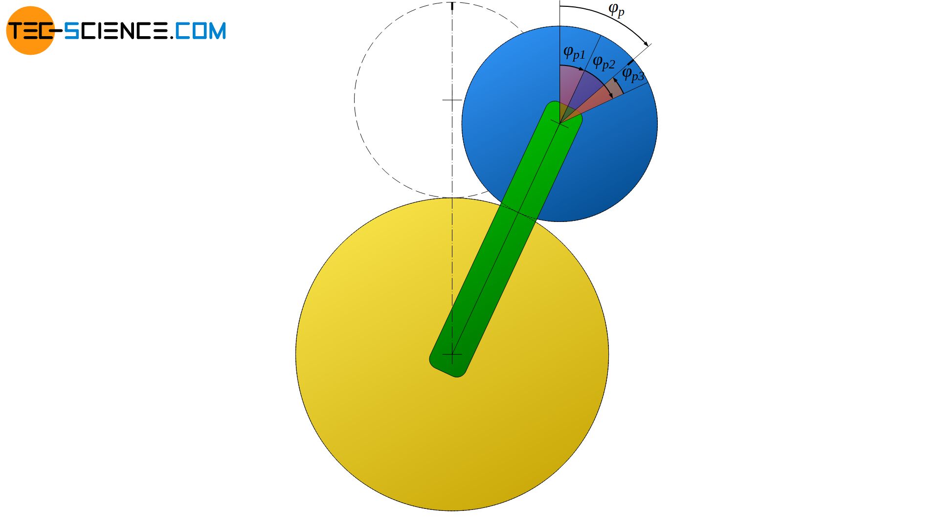
The motions of the planet gear according to the equations (\ref{P1}), (\ref{P2}) and (\ref{P3}), which have been considered separately so far, can now be superposed to the total motion:
\begin{align}
&\varphi_p = \varphi_{p1} +\varphi_{p2} + \varphi_{p3}\\[5px]
\label{P}
&\underline{\varphi_{p} = \cdot \varphi_c + \frac{d_s}{d_p} \cdot \varphi_c – \frac{d_s}{d_p} \cdot \varphi_s } \\[5px]
\end{align}
The angular positions φ contained in this equation result from the respective angular velocity ω and the elapsed time t (φ=ω⋅t), whereby the angular velocity is directly related to the rotational speed n by ω=2π⋅n:
\begin{align}
&\varphi = \omega \cdot t ~~~ \text{with} ~~~ \omega = 2 \pi \cdot n ~~~\text{applies:} \\[5px]
\label{varp}
&\underline{\varphi = 2 \pi \cdot n \cdot t} \\[5px]
\end{align}
If equation (\ref{varp}) is used in equation (\ref{P}), the following relationship ultimately results between the rotational speed of the planet gear nP and the rotational speeds of the sun gear ns and the carrier nc:
\begin{align}
&2 \pi \cdot n_p \cdot t = 2 \pi \cdot n_c \cdot t + \frac{d_s}{d_p} \cdot 2 \pi \cdot n_c \cdot t – \frac{d_s}{d_p} \cdot 2 \pi \cdot n_s \cdot t \\[5px]
&n_p =n_c + \frac{d_s}{d_p} \cdot n_c – \frac{d_s}{d_p} \cdot n_s ~~~~~~~~\text{|} \cdot d_p \\[5px]
&n_p \cdot d_p =n_c \cdot d_p + d_s \cdot n_c – d_s \cdot n_s \\[5px]
\label{g}
&\boxed{n_p \cdot d_p = n_c \cdot \left(d_p + d_s \right) – n_s \cdot d_s} \\[5px]
\end{align}
Since the pitch circle diameter d of a gear is directly proportional to the number of teeth z, the equation above can also be expressed by the respective number of teeth:
\begin{align}
\label{pln}
&\boxed{n_p \cdot z_p = n_c \cdot \left(z_p + z_s \right) – n_s \cdot z_s} \\[5px]
\end{align}
This equation is called the fundamental formula of planetary gears (also called Willis equation). The Willis equation is used to determine the different transmission ratios depending on the mode of operation, which will be explained in more detail in the article Willis equation for planetary gears.
")


