Learn more about the derivation of the different transmission ratios of planetary gears in this article.
Willis equation for planetary gears
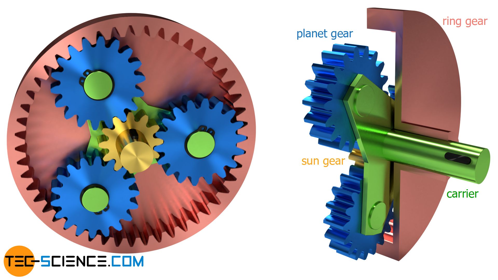
In the article Willis equation for planetary gears, the following fundamental equation was derived describing the motion of sun gear (s), ring gear (r) and carrier (c) of a planetary gear:
\begin{align}
\label{pl}
&\boxed{n_r \cdot z_r = n_c \cdot \left(z_r + z_s \right) – z_s \cdot n_s} \\[5px]
\end{align}
In this equation, n denotes the rotational speed of the components and z the number of teeth of the respective gears. This equation can now be used to show the different transmission ratios of planetary gears.
Transmission ratios
With a single planetary gear set one will obtain three different modes of operation, depending on which component (sun gear, carrier or ring gear) is fixed. Input and output are then carried out by the other two components. Which transmission ratios result in each case, is shown in the next section.
Fixed sun gear
If the sun gear is fixed (ns=0) and the gearbox input is carried out by the ring gear and the output by the carrier, the following transmission ratio is=nr/nc results according to equation (\ref{pl}):
\begin{align}
&n_r \cdot z_r = n_c \cdot \left(z_r + z_s \right) – z_s \cdot \underbrace{n_s}_{=0} \\[5px]
&n_r \cdot z_r = n_c \cdot \left(z_r + z_s \right) \\[5px]
&\frac{n_r}{n_c} = i_s = \frac{z_r+z_s}{z_r} \\[5px]
\label{i_s}
&\boxed{i_s = 1+\frac{z_s}{z_r}} ~~~1<i_s<2 \\[5px]
\end{align}
Equation (\ref{i_s}) shows that the transmission ratio is always greater than 1, i.e. the rotational speed is decreased by the planetary gearbox. But the transmission ratio is also limited to a maximum value, since the number of teeth of the sun gear must always be smaller than that of the ring gear (otherwise the sun gear would be larger than the surrounding ring gear). In the theoretical limiting case, if the sun gear is as large as the ring gear and therefore both have identical numbers of teeth, the teeth ratio becomes zs/zr=1 and the transmission ratio 2 at most.
If input and output are reversed, i.e. the gearbox input is carried out by the carrier and the output by the ring gear, then the transmission ratio range lies between 1 and 0.5.
Fixed ring gear
A further possibility for speed conversion is obtained, when the ring gear is fixed (nr=0) and the gearbox input is carried out by the sun gear and the output by the carrier. This results in the following transmission ratio ir=ns/nc:
\begin{align}
&\underbrace{n_r}_{=0} \cdot z_r = n_c \cdot \left(z_r + z_s \right) – z_s \cdot n_s \\[5px]
&0 = n_c \cdot \left(z_r + z_s \right) – z_s \cdot n_s \\[5px]
&\frac{n_s}{n_c} = i_r = \frac{z_r+z_s}{z_s} \\[5px]
\label{i_r}
&\boxed{i_r = 1+\frac{z_r}{z_s}} ~~~2<i_r<\infty \\[5px]
\end{align}
In the present case one also obtains a reduced rotational speed, because the transmission ratio will be greater than 2 in any case, since the number of teeth of the ring gear is always greater than that of the sun gear [the teeth ratio is thus greater than 1 (zr/zs>1)]. The transmission ratio is not limited to a maximum value, since the ring gear and thus its number of teeth can in principle be chosen as large as desired and the transmission ratio then strives towards infinity.
If, in the opposite case, the gearbox input is no longer carried out by the carrier but by the ring gear, then the reciprocal transmission ratios with a range between 0 and 0.5 are obtained.
Fixed carrier
A last possibility for the transmission ratio is obtained when the carrier ist fixed and the gearbox input is carried out by the sun gear and the output by the ring gear. In this case the following transmission ratio i0=ns/nr results:
\begin{align}
&n_r \cdot z_r = \underbrace{n_c}_{=0} \cdot \left(z_r + z_s \right) – z_s \cdot n_s \\[5px]
&n_r \cdot z_r = – z_s \cdot n_s \\[5px]
&\frac{n_s}{n_r} = i_0 = -\frac{z_r}{z_s} \\[5px]
\label{i_0}
&\boxed{i_0 = -\frac{z_r}{z_s}} ~~~\text{“stationary transmission ratio”}~~~-\infty<i_0<-1 \\[5px]
\end{align}
First of all, the negative sign is noticeable in the transmission ratio of equation (\ref{i_0}). It indicates that the direction of rotation between input and output shaft changes (“reverse gear”). In the present case, the transmission ratio ranges between -∞ and -1 and in the opposite case (when input and output are reversed) between -1 and 0.
Note, that in this case the planetary gear works like a stationary gearbox without moving rotational axes. For this reason, the transmission ratio in the case of a fixed carrier also called fixed carrier transmission ratio or stationary transmission ratio i0!
Direct drive
A planetary gear can also be used as a so-called direct drive. The carrier and the sun gear are firmly fixed to the ring gear. In this case, the rotary motion is transmitted directly from the input shaft to the output shaft (transmission ratio 1:1). Such a direct drive is used, for example, in three-speed gear hubs as the “2nd gear”.
Stationary transmission ratio (fixed carrier transmission ratio)
If one looks at the equations (\ref{i_s}), (\ref{i_r}) and (\ref{i_0}), then obviously all transmission ratios can also be expressed by the fixed carrier transmission ratio i0=-zr/zs. For a fixed sun gear, the transmission ratio is then becomes:
\begin{align}
&\boxed{i_s = 1-\frac{1}{i_0}} \\[5px]
\end{align}
For a fixed ring gear, the transmission ratio ir can be calculated as follows using the fixed carrier transmission ratio i0:
\begin{align}
&\boxed{i_r = 1-i_0}\\[5px]
\end{align}
Even the fundamental equation for planetary gears (\ref{pl}) can be expressed by the fixed carrier transmission ratio i0:
\begin{align}
&n_r \cdot z_r = n_c \cdot \left(z_r + z_s \right) – z_s \cdot n_s \\[5px]
&n_r \cdot \frac{z_r}{z_s} = n_c \cdot \left( \frac{z_r}{z_s} + 1 \right) – n_s \\[5px]
& – n_r \cdot i_0 = n_c \cdot \left(1-i_0 \right) – n_s \\[5px]
&\boxed{ n_s = n_c \cdot \left(1-i_0 \right) + n_r \cdot i_0 }~~~\text{with}~~~\boxed{i_0=-\frac{z_r}{z_s}}~~~\text{fixed carrier transmission ratio} \\[5px]
\end{align}


")