Learn more about the Willis equation applied to planetary gears in this article.
In the article Derivation of the Willis equation, the fundamental equation for epicyclic gears was derived in the following form:
\begin{align}
\label{g}
&\boxed{n_p \cdot d_p = n_c \cdot \left(d_p + d_s \right) – n_s \cdot d_s} \\[5px]
\end{align}
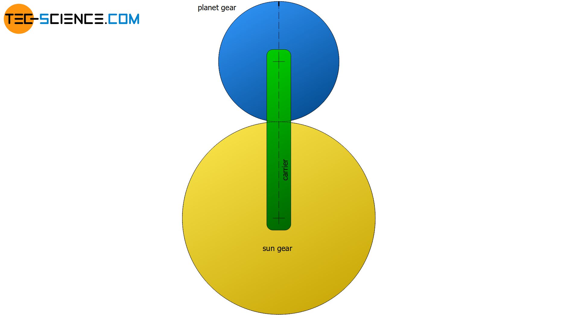
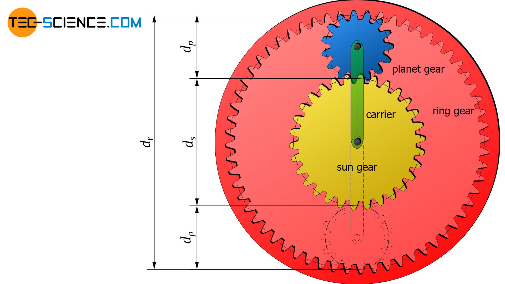
In this equation, np denotes the rotational speed and dp the diameter (pitch circle) of the planetary gear. For the sun gear, the speed is denoted by ns and the diameter by ds. The rotational speed of the carrier is denoted by nc.
The Willis equation (\ref{g}) generally applies to all planetary gears. Although the planet gears of a classic planetary gearbox are enclosed by a ring gear, this does not change the derived relationships between sun gear, planet gear and carrier. The only question that arises is how the motion of the planet gears is transferred to the ring gear.
Since a mere rolling motion without sliding between the ring gear and the planet gear takes place (considered as pitch cylinders), the velocity at the contact point must be equal. If one knows the speed vpo with which the outermost point of the planet gear moves, then this corresponds to the velocity vr of the ring gear. Otherwise, a relative motion would come up, which of course can not be the case with toothed wheels. The pitch circle radius r (or pitch circle diameter d) of the ring gear can then be used to determine its rotational speed n, since the following relationship applies between these parameters:
\begin{align}
\label{o}
&v = \omega \cdot r = \omega \cdot \tfrac{d}{2} ~~~ \text{with} ~~~ \omega = 2 \pi \cdot n ~~~\text{applies}: \\[5px]
\label{v}
&\underline{v = \pi \cdot n \cdot d} \\[5px]
\end{align}
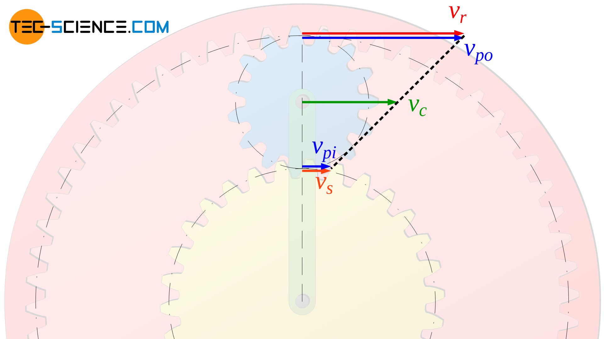
The same situation applies to the rotational speeds at the contact point between the planet gear and the sun gear. At the innermost point, the speed of the planet gear vpi must be equal to the speed of the sun gear vs. The center of gravity of the planet gear moves with the velocity vc of the carrier. There is a linear relationship between these velocities (see black dotted line in the figure above), so that the circumferential speed of the ring gear vr can be determined for a given circumferential speed of the sun gear vs and a given circumferential speed of the carrier vc.
Why is there such a linear relationship?
Why there is such a relative simple, linear relationship of the speeds will be shown in the following. For the sake of simplicity, the gears are assumed to be pitch cylinders.
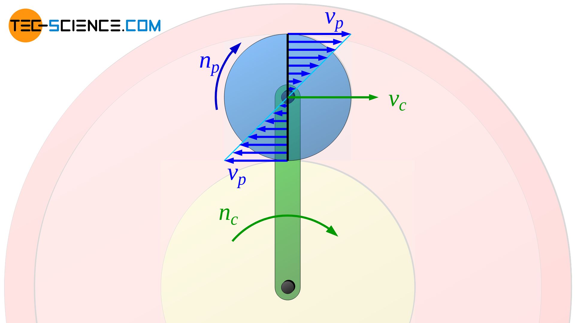
The motion of a point on the planet gear can be understood as the superposition of two motions. On the one hand, the planet gear first rotates around its own center of gravity. In this case the typical symmetrical and linear increase of the velocity according to the equation (\ref{o}) is obtained, starting from the axis of rotation of the planet gear. The maximum speeds vp are obtained at the pitch circle of the planet gear.
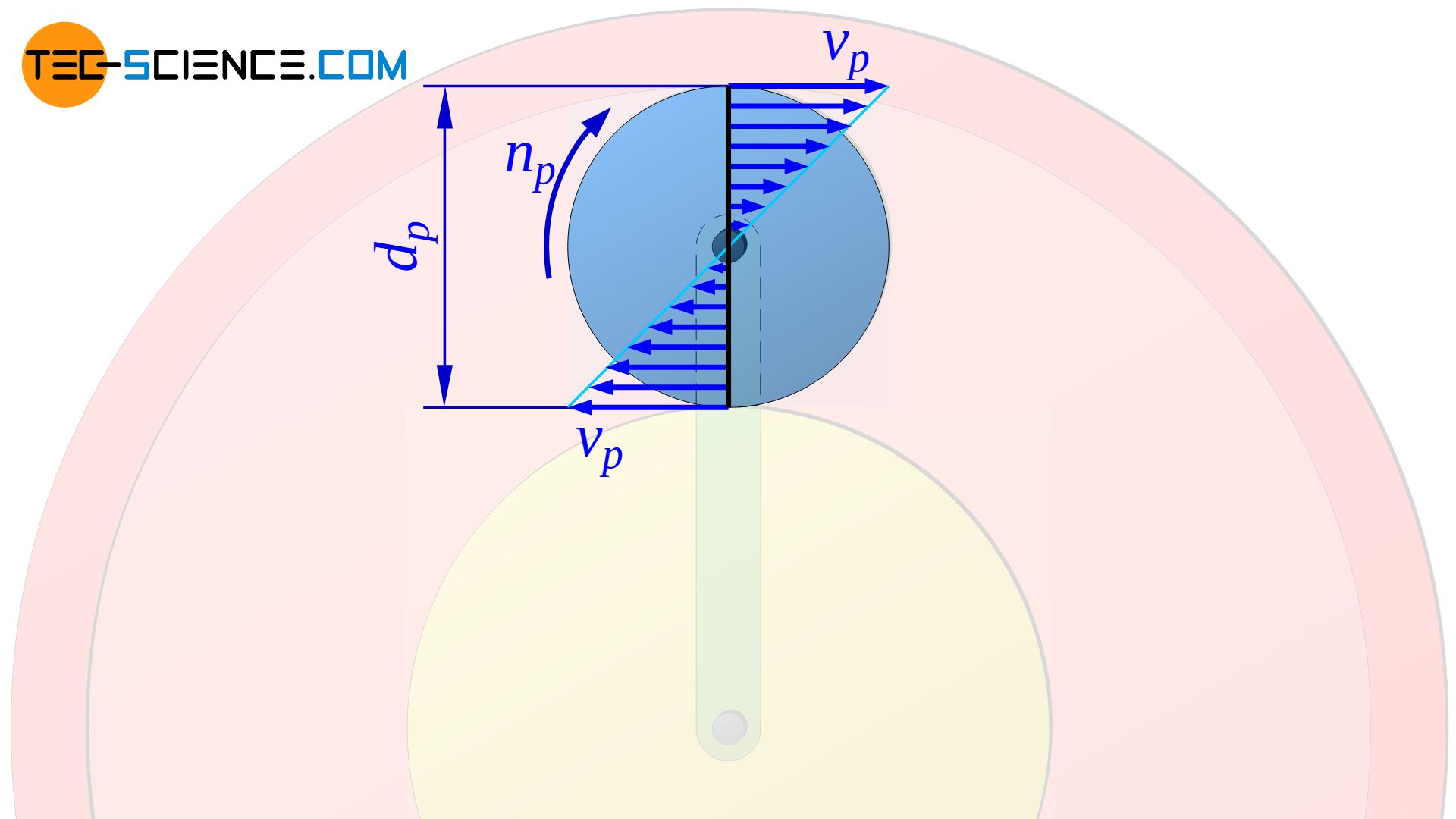
In the center of rotation, the speed is zero as long as the planet gear axis does not move. However, the axis of rotation now moves at the speed of the carrier vc. Both motions can now be superposed to the total motion.
The velocity of the planet gear at the outmost contact point with the ring gear points in the same direction as the velocity of the carrier. At the innermost point of contact with the sun gear, however, in the opposite direction. Due to the symmetrical speed distribution, the resulting speed of the planet gear at the outermost point of contact with the ring gear is therefore higher (vpo=vc+vp) to the same extent as it is lower at the innermost point of contact with the sun gear (vpi=vc-vp).
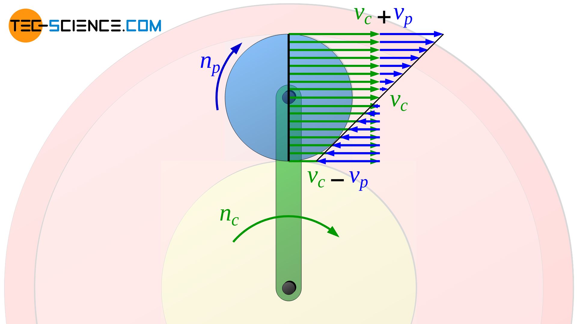
In other words, the velocity of a point on the planet gear increases linearly, starting from the point of contact with the sun gear. Since the speed of the carrier vc is assumed to be given, only the speed of the planet gear at the point of contact to the sun gear vs must be known in order to determine the circumferential speed at the opposite point of contact to the ring gear vr.
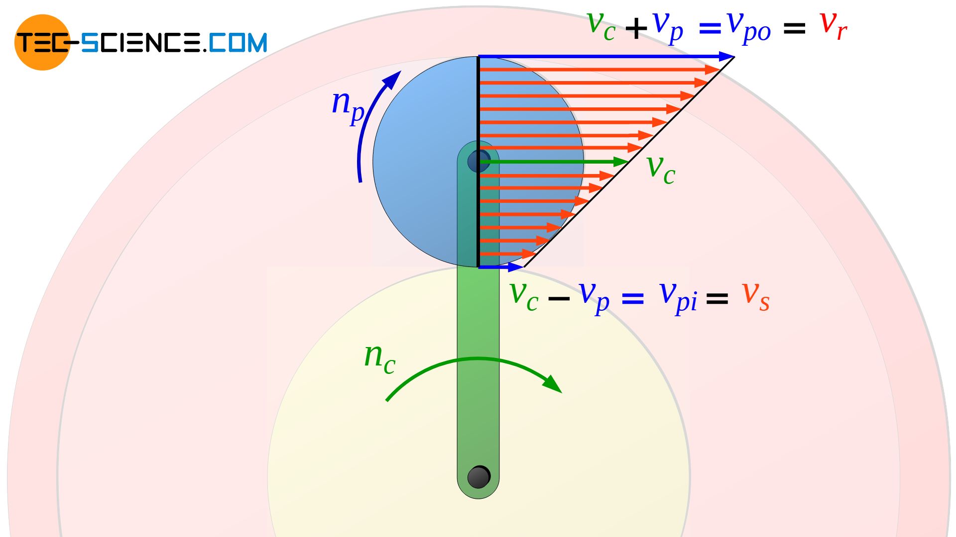
As already explained, for a mere rolling process without relative motions, the speed of the planet gear at the contact point to the ring gear (vpo=vc+vp) must be equal to the circumferential speed of the ring gear vr:
\begin{align}
&v_r\overset{!}{=}v_{po} \\[5px]
\label{v_r}
&\underline{v_r=v_c+v_p} \\[5px]
\end{align}
The same applies to the contact point between the planet gear and the sun gear. There, the speed of the planet gear (vpi=vc-vp) must be equal to the circumferential speed of the sun gear vs:
\begin{align}
&v_s\overset{!}{=}v_{pi} \\[5px]
\label{v_s}
&\underline{v_s=v_c-v_p} \\[5px]
\end{align}
If we subtract equation (\ref{v_s}) from equation (\ref{v_r}), we obtain the following relationship between the circumferential speeds of the sun gear vs, the planet gear vp and the ring gear vr:
\begin{align}
&v_r – v_s = v_c+v_p-v_c+v_p \\[5px]
&v_r = 2 \cdot v_p + v_s \\[5px]
\label{vvv}
&\underline{ v_p = \frac{v_r}{2} – \frac{v_s}{2} } \\[5px]
\end{align}
If the relationship of equation (\ref{v}) ist used in equation (\ref{vvv}), then the relationship between the corresponding rotational speeds is obtained:
\begin{align}
&v_p = \frac{v_r}{2} – \frac{v_s}{2} \\[5px]
&\pi \cdot n_p \cdot d_p = \frac{\pi \cdot n_r \cdot d_r}{2} – \frac{\pi \cdot n_s \cdot d_s}{2} \\[5px]
\label{nn}
&\boxed{n_p \cdot d_p = n_r \cdot \frac{d_r}{2} – n_s \cdot \frac{d_s}{2}} \\[5px]
\end{align}
The relation resulting from equation (\ref{nn}) can now be equated directly with the fundamental equation (\ref{g}) and one finally gets the following relation between the rotational speeds of the sun gear (S), the carrier (T) and the ring gear (H):
\begin{align}
&n_r \cdot \frac{d_r}{2} – n_s \cdot \frac{d_s}{2} = n_c \cdot \left(d_p + d_s \right) – n_s \cdot d_s \\[5px]
&n_r \cdot d_r – n_s \cdot d_s = 2 \cdot n_c \cdot \left(d_p + d_s \right) – 2 \cdot n_s \cdot d_s \\[5px]
\label{f}
&\underline{n_r \cdot d_r = 2 \cdot n_c \cdot \left(d_p + d_s \right) – d_s \cdot n_s} \\[5px]
\end{align}
Additionally, it can be used that the diameters of the ring gear, the planet gear and the sun gear are not independent from each other. The ring gear diameter dr corresponds to the sum of the sun gear diameter ds and twice the planet gear diameter dp:
\begin{align}
&d_r = d_s + 2 \cdot d_p \\[5px]
&\underline{d_p = \frac{d_r-d_s}{2}} \\[5px]
\end{align}
This results in the planetary gear equation for classic single-stage planetary gears (independent of the properties of the planet gears!):
\begin{align}
&n_r \cdot d_r = 2 \cdot n_c \cdot \left(\frac{d_r-d_s}{2} + d_s \right) – d_s \cdot n_s \\[5px]
&n_r \cdot d_r =n_c \cdot \left(d_r – d_s + 2 \cdot d_s \right) – d_s \cdot n_s \\[5px]
&\underline{n_r \cdot d_r = n_c \cdot \left(d_r + d_s \right) – d_s \cdot n_s} \\[5px]
\end{align}
Since for toothed wheels the pitch circle diameters d are proportional to the number of teeth z, the equation above can also be expressed by the number of teeth of the ring gear (zr) and the number of teeth of the sun gear (zs):
\begin{align}
\label{pl}
&\boxed{n_r \cdot z_r = n_c \cdot \left(z_r + z_s \right) – z_s \cdot n_s} \\[5px]
\end{align}
This equation can be used to explain the different transmission ratios of planetary gears. This will be discussed in more detail in the article Transmission ratios of planetary gears.
")


")