A planetary gear is an epicyclic gear in which several gears (planet gears) mesh with a central gear (sun gear).
Stationary gearbox
So-called stationary gearboxes are characterised by the fact that the gear wheels have stationary axes of rotation. The figure below shows a 2-stage stationary transmission with three gears. An input gear drives an output gear by an idler gear (intermediate gear).
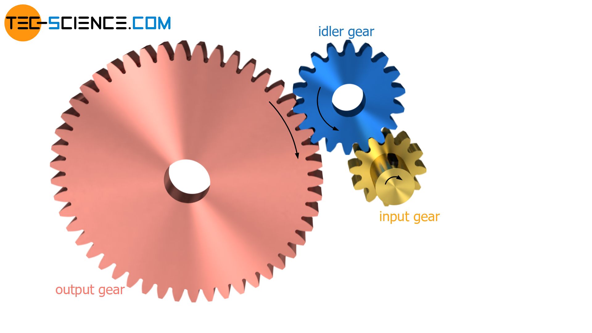
The transmission ratio i1 or i2 of the respective gear stages is determined by the ratio of the corresponding number of teeth on the idler gear zidler and input gear zin or output gear zout.
\begin{align}
&\text{1. Stage:} ~~~i_1 = \frac{z_{idler}}{z_{in}} \\[5px]
&\text{2. Stage:} ~~~i_2 = \frac{z_{out}}{z_{idler}} \\[5px]
\end{align}
The total transmission ratio itotal of the 2-stage stationary gear unit (therefore also referred to as stationary transmission ratio or fixed carrier train ratio) is obtained by multiplying the transmission ratios i1 and i2:
\begin{align}
&i_{total} =i_1 \cdot i_2 =\frac{z_{idler}}{z_{in}} \cdot \frac{z_{out}}{z_{idler}} \\[5px]
\label{i}
&\boxed{i_{total} = \frac{z_{out}}{z_{in}}} ~~~\text{stationary transmission ratio} \\[5px]
\end{align}
For the overall transmission ratio, obviously only the number of teeth of the output gear and the number of teeth of the input gear are of relevance! The number of teeth of the intermediate gear does not matter.
From stationary gearbox to planetary gearbox
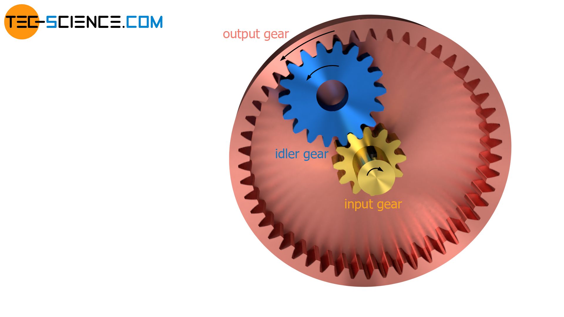
Internal toothed gear as output gear
Instead of the externally toothed output gear, a ring gear with internal toothing can also be used in principle. As long as the number of teeth is not changed, this has no effect on the overall transmission ratio according to the equation (\ref{i}). Only the sense of rotation of the output gear will change as a result.
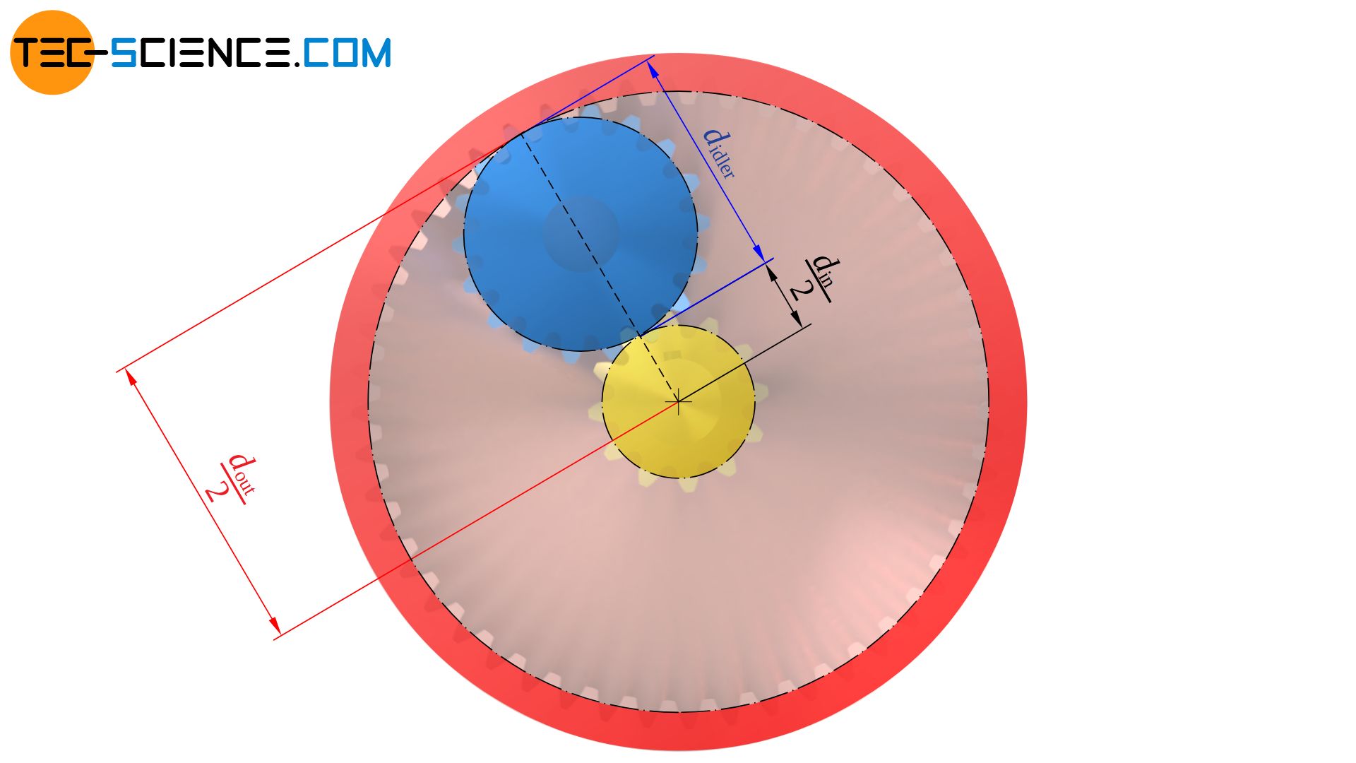
In general, the axes of rotation of the input shaft and the output shaft are not perfectly aligned on a common axis, but have an offset. However, by cleverly choosing the diameter and thus the number of teeth of the idler gear, it is possible to ensure that the input shaft and the output shaft are on a common axis.
Note that the number of teeth of the idler gear according to the equation (\ref{i}) has no effect on the overall transmission ratio anyway and can therefore be arbitrarily chosen in principle!
If the input and output shafts are to be coaxial (“coaxial” = “aligned on a common axis”), the pitch circle diameter of the intermediate gear must correspond exactly to the difference between the pitch circle radii of the output and input gear. Since the number of teeth is directly proportional to the pitch circle diameter, the respective number of teeth can be used instead of the pitch circle diameter. As a result, the number of teeth of the idler gear must be just half the difference between the number of teeth of the output and input gear.
\begin{align}
&d_{idler} = r_{out}-r_{in}=\frac{d_{out}}{2}-\frac{d_{in}}{2}=\frac{d_{out}-d_{in}}{2} \\[5px]
&\boxed{z_{idler} =\frac{z_{out}-z_{in}}{2}} \\[5px]
\end{align}
Inserting additional idler gears
A disadvantage of the present gearbox is that the input shaft (as well as the output shaft) is subjected to a bending load by the one-sided flank force. In the figure below, F denotes the reaction force of the idler gear acting on the tooth flank of the input gear.
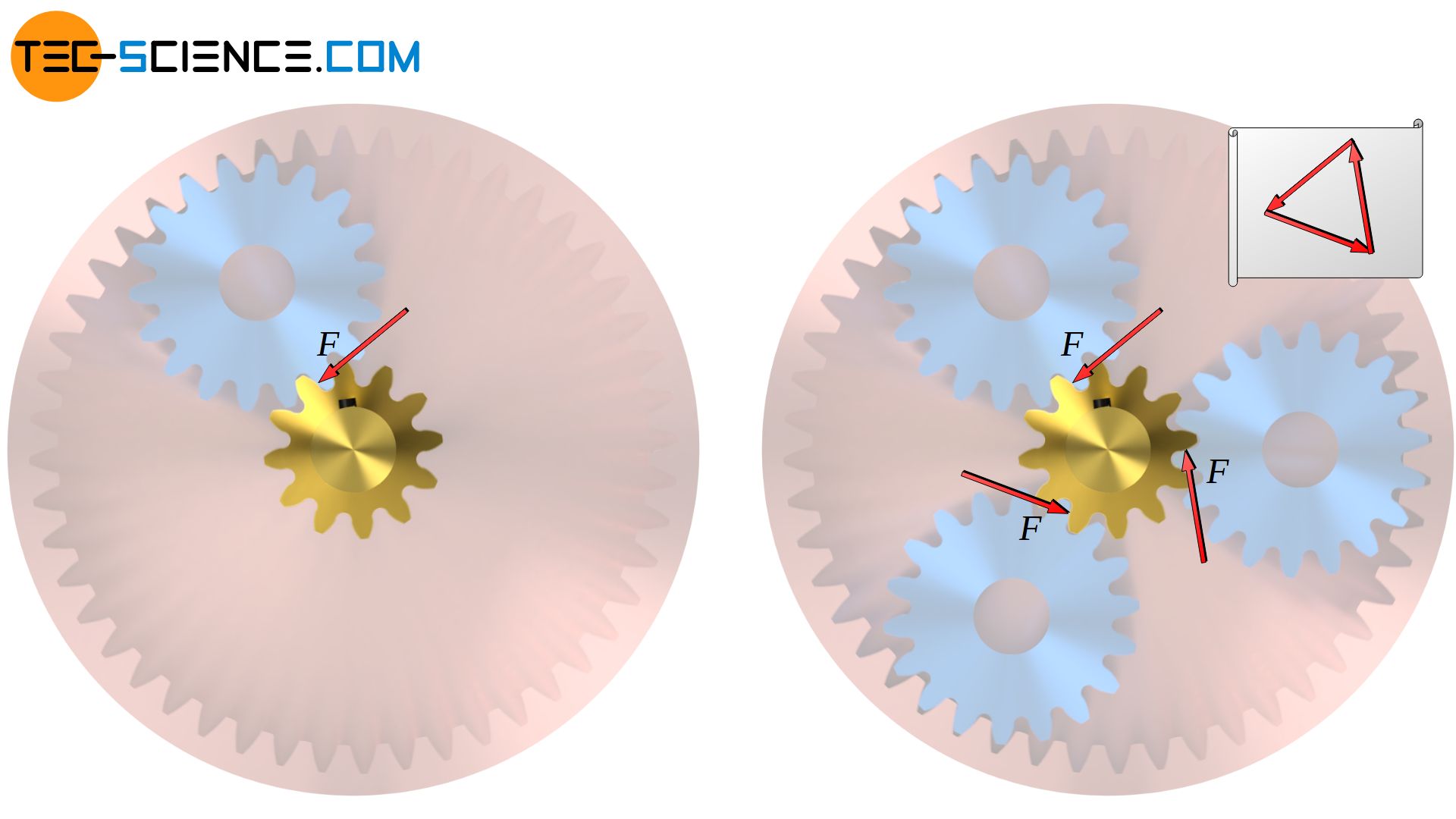
However, bending stresses can be avoided if several intermediate gears are arranged symmetrically so that the flank forces compensate each other in their bending effect. In the case obtained with three idler gears, the input and output shafts are no longer subjected to bending load but only to torsion.
Mounting the idler gears on a carrier
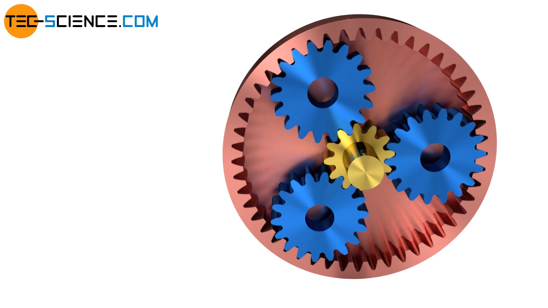
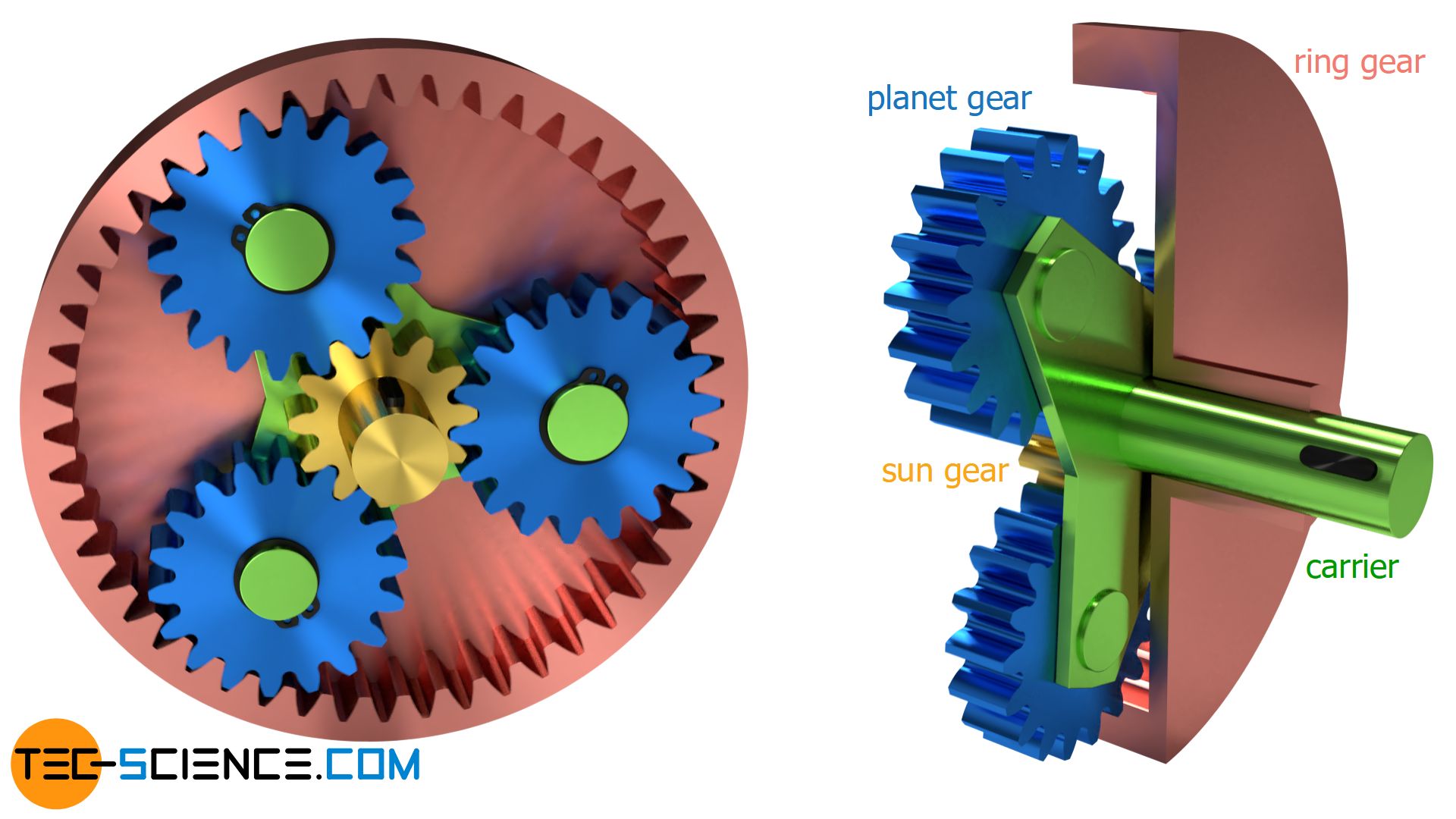
In principle, the present gearbox already forms the pre-stage of a planetary gear. The last step consists only of mounting the idler gears on a so-called carrier. The carrier itself is connected to a shaft and is guided coaxially through the output shaft, which is designed as a hollow shaft.
With the carrier, the planetary gear is in principle complete. In this operating mode, it has a stationary transmission ratio (fixed carrier train ratio) according to the equation (\ref{i}). In terms of function, in this operating state the planetary gear does not yet differ from the stationary gearbox described above.
However, this changes if the planetary gear is used in a different way. This is because the output of the planetary gearbox does not always have to take place at the aforementioned “output shaft”. It is also possible to use the carrier as the output shaft, while the hollow shaft of the internally toothed gear is firmly locked. In this case, the idler gears now “orbit” the centrally located drive gear like planets a sun; hence the term planetary gear. The transmission ratio of the planetary gear in this mode of operation now differs from that of the stationary gearbox!
The gearwheels previously referred to as “idler gears” are generally referred to as planet gears and the centrally located external gear is referred to as the sun gear. The internally toothed gear wheel is generally called ring gear or annulus.
In contrast to stationary gears, planetary gears (also called epicyclic gears) are characterized by moving axis of rotation!
At this point, the necessity of a symmetrical arrangement of the planet gears becomes also apparent, as otherwise enormous unbalance forces would occur at high rotational speeds.
With a planetary gear it is not only possible to lock firm the ring gear and let the output take place through the carrier. Many other variants are possible, each with a different transmission ratio (see next section “Transmission ratios”). This makes the planetary gear particularly suitable for transmissions such as hub gears of bicycles or automatic transmissions of automobiles.
The advantage of planetary gears over conventional stationary transmissions is their compact design and the advantage that the shafts are all coaxial. For very large transmission ratios, it is also possible to connect several planetary gears in series.
Transmission ratios
With a planetary gear, different transmission ratios can be achieved, depending on the shaft at which the input or the output takes place and the gearwheel that is locked firm. The different transmission ratios will be explained using the example of the planetary gear shown below. The sun gear has zs = 12 teeth, the planet gears zp = 18 teeth and the ring gear zr = 48 teeth.
The derivation of the transmission ratios shown in the following will be discussed in detail in a separate article due to their complexity.
Fixed ring gear
The highest transmission ratio of i=5 is obtained in this case when the gearbox is driven by the sun gear and the ring gear is fixed. The output then takes place by the carrier. Obviously, the lowest transmission ratio of i=0.2 (=1/5) is obtained when input and output are reversed while the ring gear remains fixed. The direction of rotation of the input and output shafts is maintained in both cases.
Fixed carrier
The second highest transmission ratio of i=4 is achieved in the present case if the planetary gearbox is still driven by the sun gear, but this time the carrier is fixed and the output is done by the ring gear. Consequently, the second lowest transmission ratio of i=0.25 (=1/4) is obtained by reversing the input and output. In both cases, however, the sense of rotation between input and output shaft is different! In such a case the transmission ratio has a negative sign (see table below). In this way a reverse gear can be generated.
Fixed sun gear
A further transmission ratio is obtained when the planetary gearbox is driven by the ring gear and the sun gear is fixed. In this case the carrier serves as the gearbox output. The transmission ratio now becomes i=1.25, while the sense of rotation is remained. If the output and the input of the gearbox are reversed, the transmission ratio is i=0.8 (=1/1.25).
Direct drive
With a planetary gear a so-called direct drive is also possible. All components of the planetary gear are then firmly connected to each other. The transmission ratio in this case is i=1. Such a direct drive is used, for example, in three-speed gear hubs as the “2nd gear”.
Summary
The various transmission ratios are summarised in the table below. In round brackets, the transmission ratios are given for reversed input and output (reciprocal transmission ratio). Negative signs indicate that the sense of rotation changes.
| Variants | 1 | 2 | 3 | 4 |
| fixed | ring gear | carrier | sun gear | direct drive |
| input | sun gear | sun gear | ring gear | |
| output | carrier | ring gear | carrier | |
| transmission ratio | \begin{align} \notag i = 1+\frac{z_r}{z_s} \\[5px] \end{align} | \begin{align} \notag i = -\frac{z_r}{z_s} \\[5px] \end{align} | \begin{align}\ \notag i = 1+\frac{z_s}{z_r} \\[5px] \end{align} | \begin{align} \notag i = 1 \\[5px] \end{align} |
| range of the transmission ratio (reciprocal) | 2 < i < ∞ (0 < i < 0.5) | -∞ < i < -1 (-1 < i < 0) | 1 < i < 2 (0.5 < i < 1) | i = 1.00 (i = 1.00) |
| transmission ratio of the example used (reciprocal) | 5.00 (0.20) | -4.00 (-0.25) | 1.25 (0.80) | 1.00 (1.00) |
In manual transmissions, the shifting of various transmission ratios is performed by clutches that allow certain components (sun gear, carrier or ring gear) to be fixed depending on the desired gear. For functional reasons, however, not all of the transmission ratios shown in the table above can be achieved with a single planetary gear (planetary gear set). However, the transmission ratios can be increased enormously if several individual planetary gear sets are combined. In practice, up to three planetary gear sets are common in one gearbox.
")


