In this article, you will learn more about the design, the advantages and disadvantages of a cycloidal drive and its application.
Operating principle
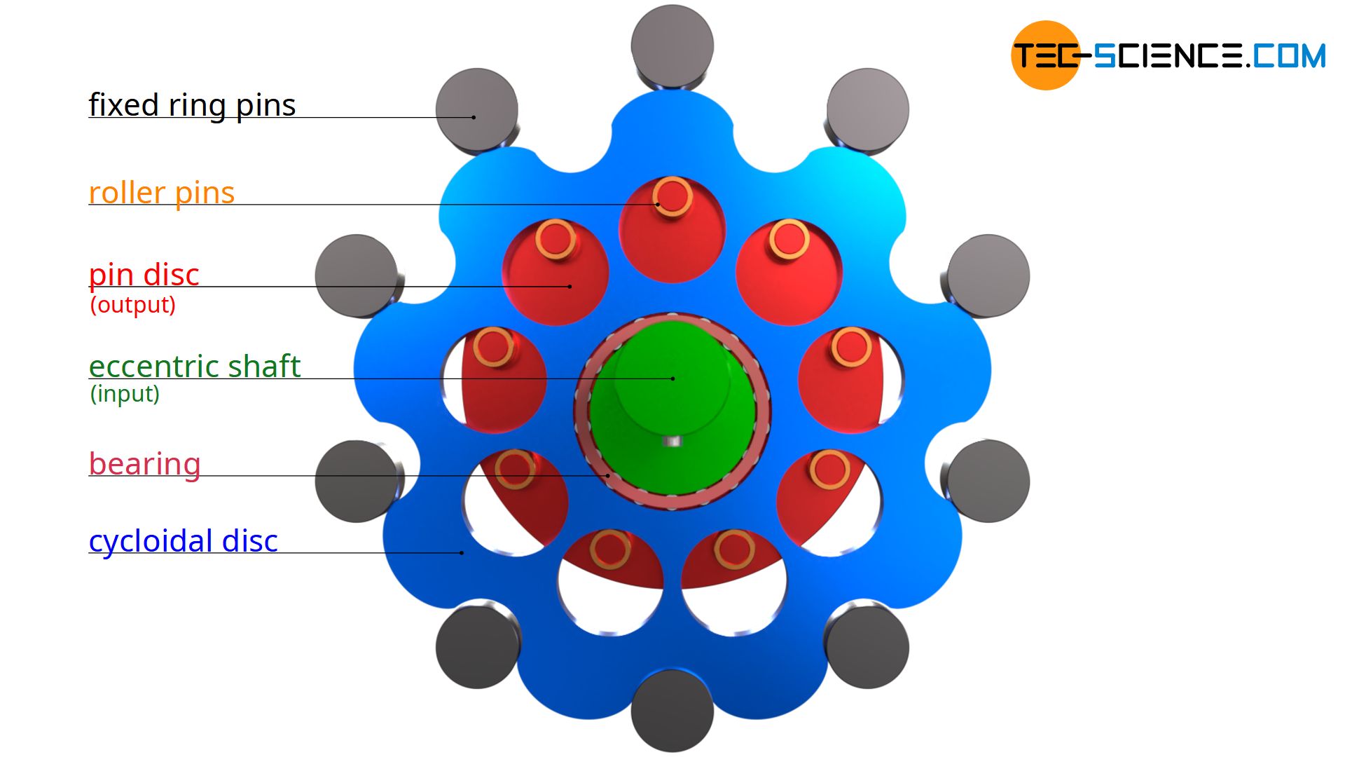
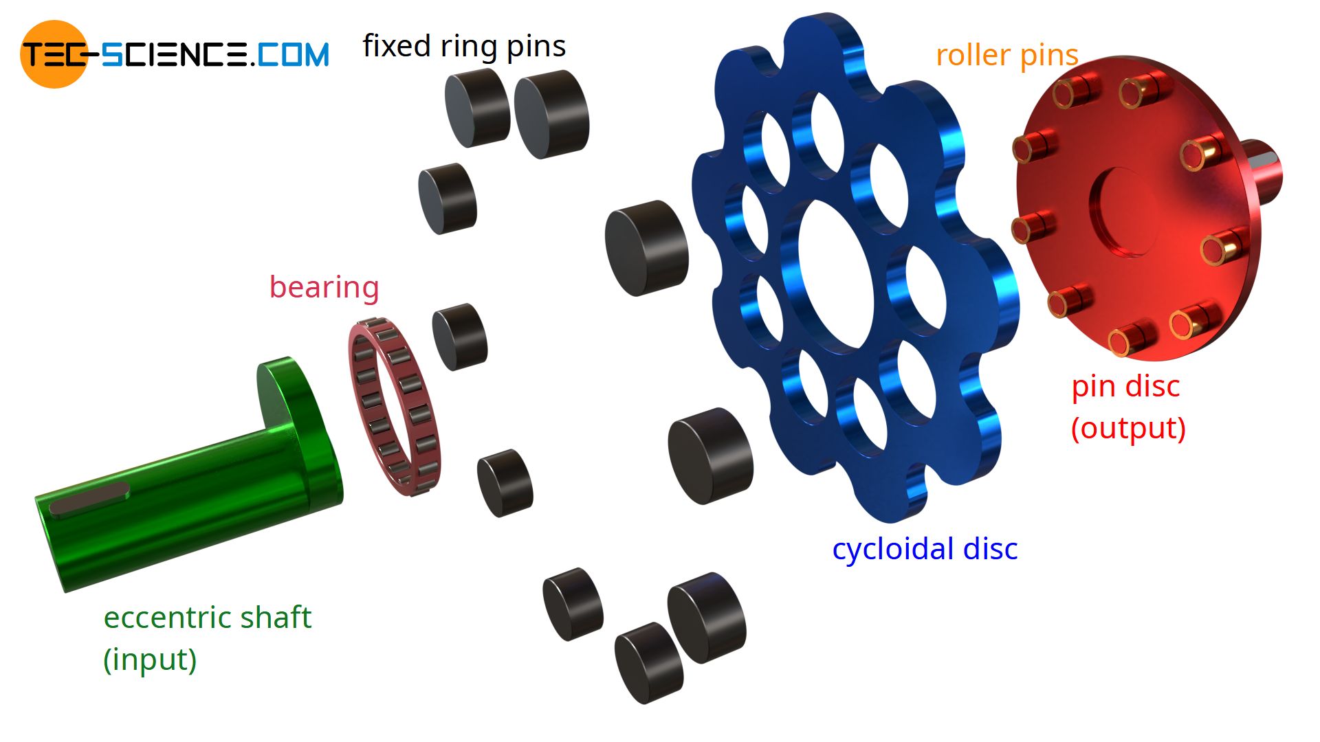
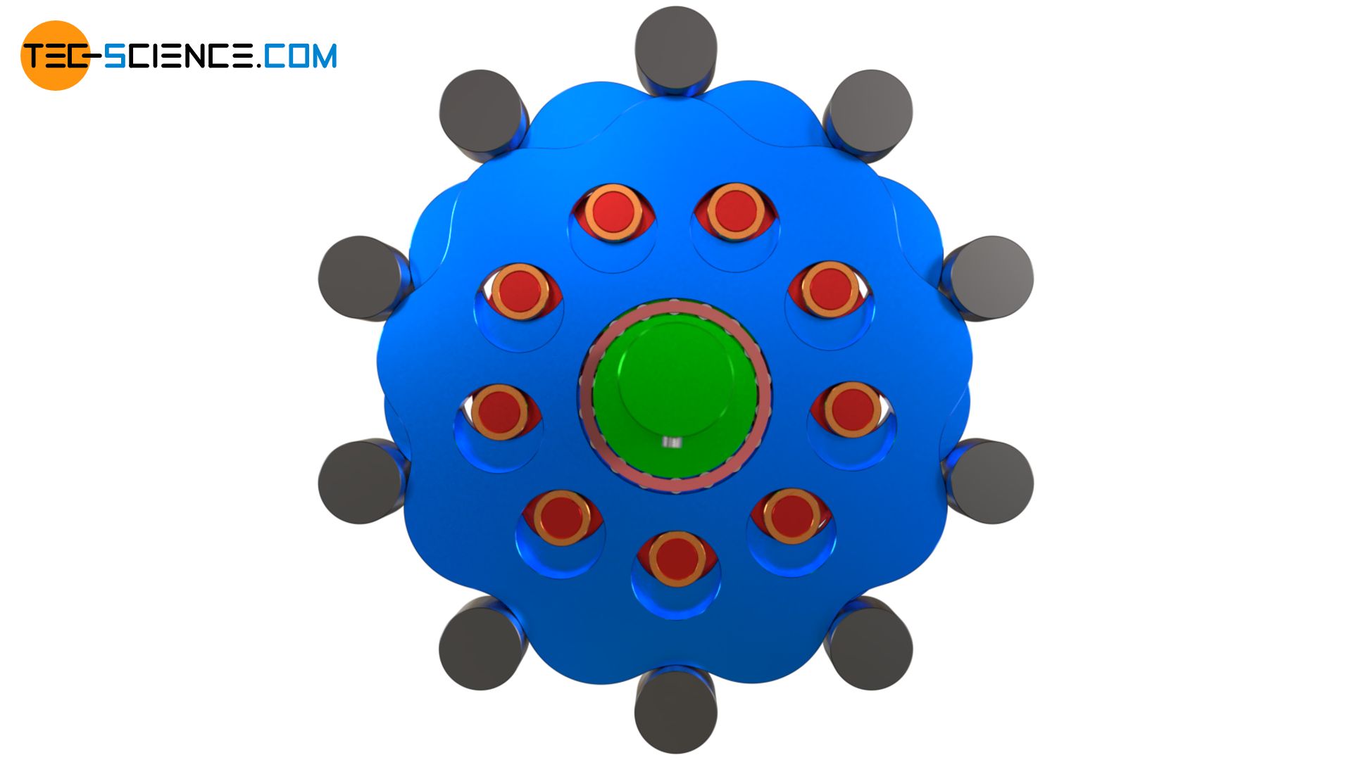
The animation below shows the structure and operating principle of a cycloidal drive.
An eccentric shaft (drive shaft) first drives a cycloidal disk. Fixed ring pins are arranged in a circle around the eccentric shaft, in which the cycloidal disc engages. Due to the eccentric motion, the cycloidal disc is driven around these pins so that the cycloidal disc rotates around its axis of symmetry. There are holes in the cycloidal disc which, unlike the eccentric shaft, now rotate clockwise. Roller pins of a pin disc engage in these holes. In this way, the cycloidal disc drives the pin disc, to which the centrally mounted output shaft is attached and which is coaxial with the input shaft.
If one compares the rotational speed of the input shaft with the speed of the output shaft in the upper animation, a speed reduction obviously occurs in addition to the reversal of the direction of rotation. In this animation, the pin disc rotates by a total of 40° during a complete rotation of the eccentric shaft (360°). Only after 9 revolutions of the input shaft has the output shaft completed a complete revolution. The transmission ratio of the gearbox is thus 9:1.
The heart of a cycloidal drive is the cycloidal disc, whose geometry plays a central role in the kinematic of the gearbox. The profile of such a disc can be traced back to a cycloid. That’s why the gearbox is called a cycloidal drive. Since cycloidal drives are used to reduce the speed, they are also referred to as cycloidal speed reducers. The construction of the geometry of the cycloidal disc is described in more detail in the article “Construction of the cycloidal disc“.
Due to the symmetrical load distribution, two cycloid discs are often used in practice, which are then offset by 180°. This ensures that the unbalance forces compensate each other, resulting in smoother operation at high speeds. The double design of the cycloidal discs also allows very high torques to be transmitted. In addition, the cycloid discs are often designed with a so-called shortened cycloid, which results in a
less lobed profile with reduced eccentricity and smaller hole diameters in the cycloid discs (more on this in the article “Construction of the cycloidal disc“.
Demonstration of the operating principle
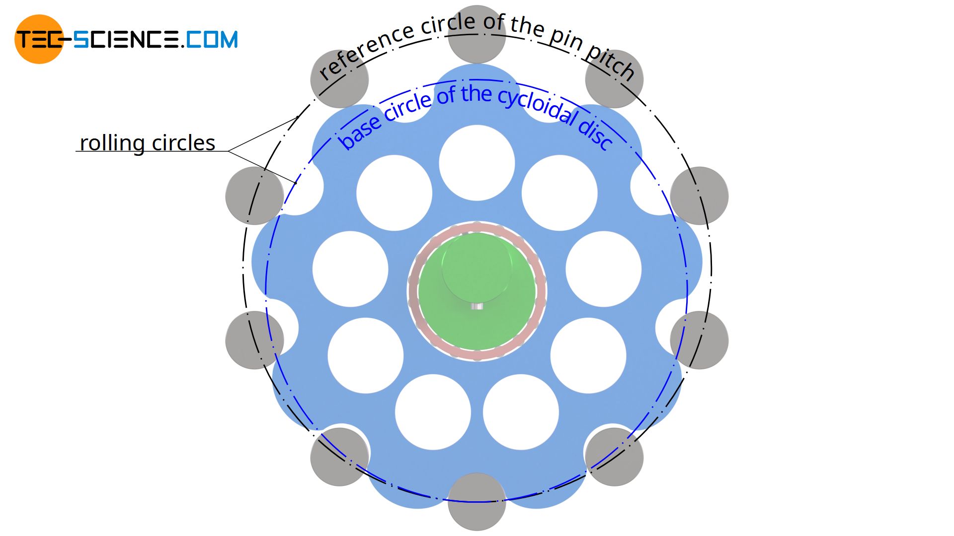
The kinematics of a cycloidal drive appear very complex at first. But the idea behind it, which leads to such a kinematics, is quite simple. First imagine a fixed ring, on the inside of which a disc rolls. The disc is driven around the inside of the fixed ring with the aid of an eccentric shaft. The rolling disc thus rotates around its axis of symmetry.
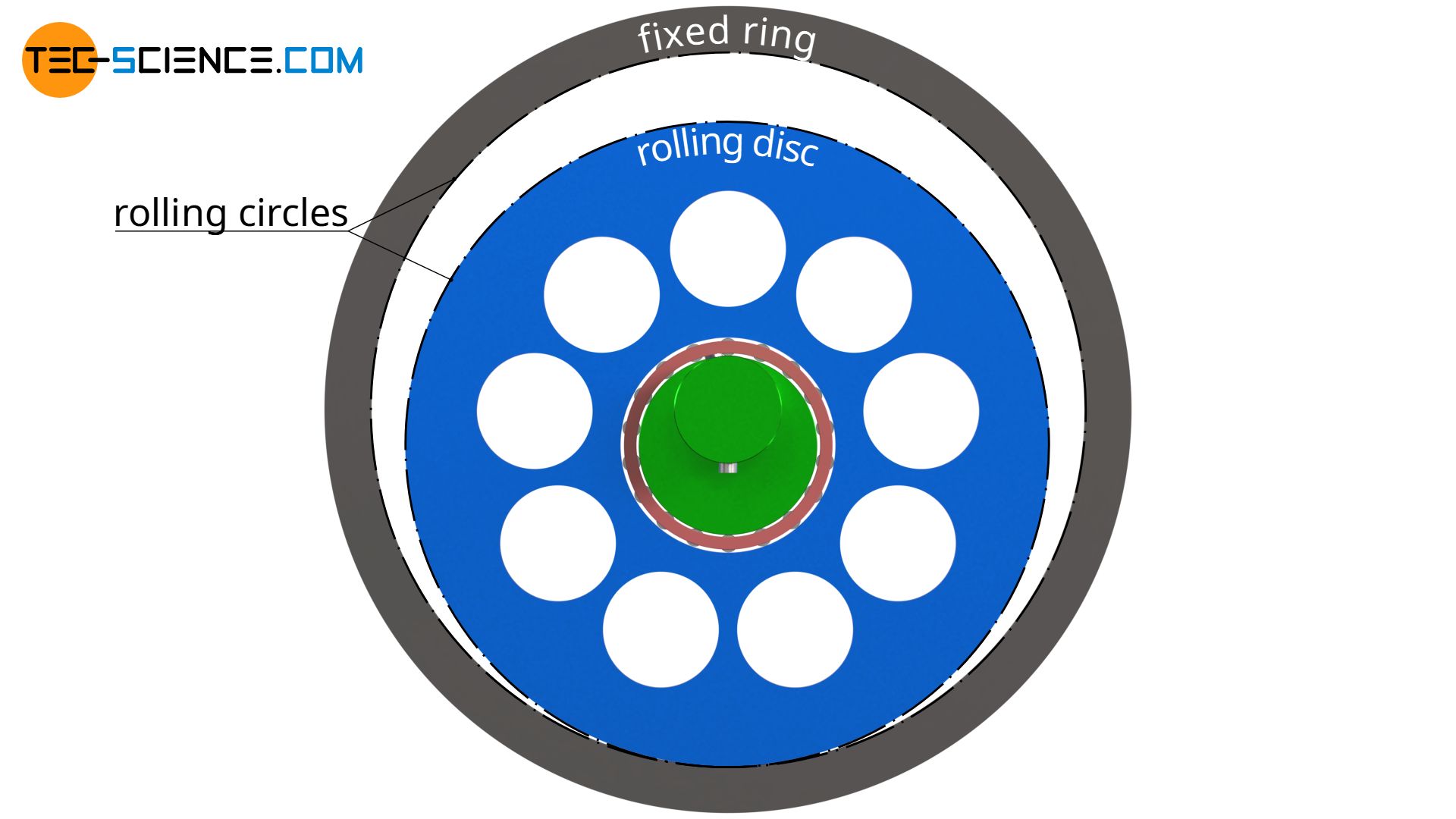
Such a gearbox does not yet provide a large power transmission, since the power transmission is only achieved by frictional forces between the ring and the disc. Therefore a positive fit is used. This is achieved by a toothing between the fixed ring and the rolling disc.
A cycloid is used as the tooth form for the rolling disc. The rolling disc serves as the base circle for the construction of the epicycloid. The fixed ring, in turn, serves as the reference circle on which the pins are arranged, in which the cycloid disc engages.
Transmission ratio
The transmission ratio of a cycloidal drive is determined by the number of the fixed ring pins N and the number of the lobes of the cycloidal disc n (which is identical to the number of the space between the lobes!). The number of lobes in the cycloidal disc must always be smaller than the number of surrounding pins, otherwise the disc would be larger than the reference circle of the pins and the disc would not even fit between the pins. In most cases the cycloidal disc has one lobe less than the number of pins.
Using the example with N=10 pins and n=9 lobes, the calculation of the transmission ratio will be derived in the following. After one revolution of the eccentric shaft, the cycloidal disc has obviously engaged with a total of N=10 pins. Since the disc has only n=9 lobes, it must have moved by one lobe during one revolution of the drive shaft. This corresponds to one ninth of a full revolution.
Thus, the input shaft (eccentric shaft) must rotate 9 times so that the cycloidal disc and with it the output shaft (pin disc) perform a full rotation. The transmission ratio in this case would therefore be 1:9.
If, for example, the cycloidal disc had only n=7 lobes on its circumference, then it would have moved on by 3 lobes during a revolution around the N=10 pins. With one revolution of the input shaft, the output shaft would then have moved on by 3 times 1/7 revolutions. The input shaft would then have to rotate 7 times for the output shaft to make 3 revolutions. In this case, the transmission ratio would be 7:3.
If this principle is generalized, the transmission ratio of a cycloidal drive can be determined as follows on the basis of the number of lobes of the cycloidal disc n and the difference to the number of pins N:
\begin{align}
&\boxed{i = \frac{n}{N-n} } \\[5px]
\end{align}
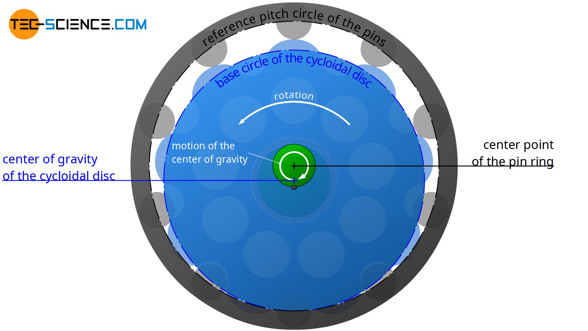
Note: Because the cycloidal disc rolls on the inside of the reference pitch circle of the pins, the rotational motion of the disc around its center of gravity is opposite to the circular motion of the center of gravity itself (moving around the center point of the pin ring). Therefore the disc does not rotate completely around its centre of gravity when rotating around the pins. This would only be the case if the disc would roll on the outside of the ring pins (the rotational motion of the disc around its center of gravity and the motion of the center of gravity itself would then be identical).
Cycloidal drive vs. planetary gear
When it comes to large transmission ratios in a compact design, two gear types are particularly suitable: The planetary gear and the cycloidal drive. The similarities between the two gear types become particularly clear when the ring gear of the planetary gearbox is fixed. The gearbox is driven by the sun gear and the output is done by the carrier.
In the case of the planetary gear, the rotary axes are the axes of the planet gears (shown in blue) and in the case of the cycloidal gear, the axes of the cycloidal discs. While the planet gears are driven by a sun gear, the cycloid discs are driven by an eccentric shaft. As they rotate, the planet gears move around the inside of the ring gear. In the same way, the cycloid discs rotate around the fixed pins arranged in a circle. The motion of the planet gears drives the carrier and transmits the power to the output shaft. In the same way, the motion of the cycloidal discs drives a pin disc, which in turn transmits the power to the output shaft.
| Planetary gear | Cycloidal drive | |
| moving axles | planet gears | cycloidal discs |
| driven by | sun gear | eccentric shaft |
| orbiting | ring gear | fixed ring pins |
| driving the | carrier | pin disc |
Compared to planetary gears, cycloidal drives are very robust against shock loads. In addition, cycloidal drives achieve significantly better positioning accuracy due to their very low backlash and high torsional stiffness. Therefore cycloidal drives are ideally suited for all types of drive technologies (e.g. for servo motors in robotics) and especially for heavy loads.
Cycloidal drives generally have a lower mass and a more compact design than planetary gears, especially at high transmission ratios, and have a longer service life. At relatively low gear ratios of less than 20, however, planetary gears usually offer better advantages and higher efficiency, depending on the application.
")


")