Learn more about the design of the cycloidal disc of a cycloidal drive in this article.
Design of the cycloidal disc
Cycloidal disc with ordinary cycloid
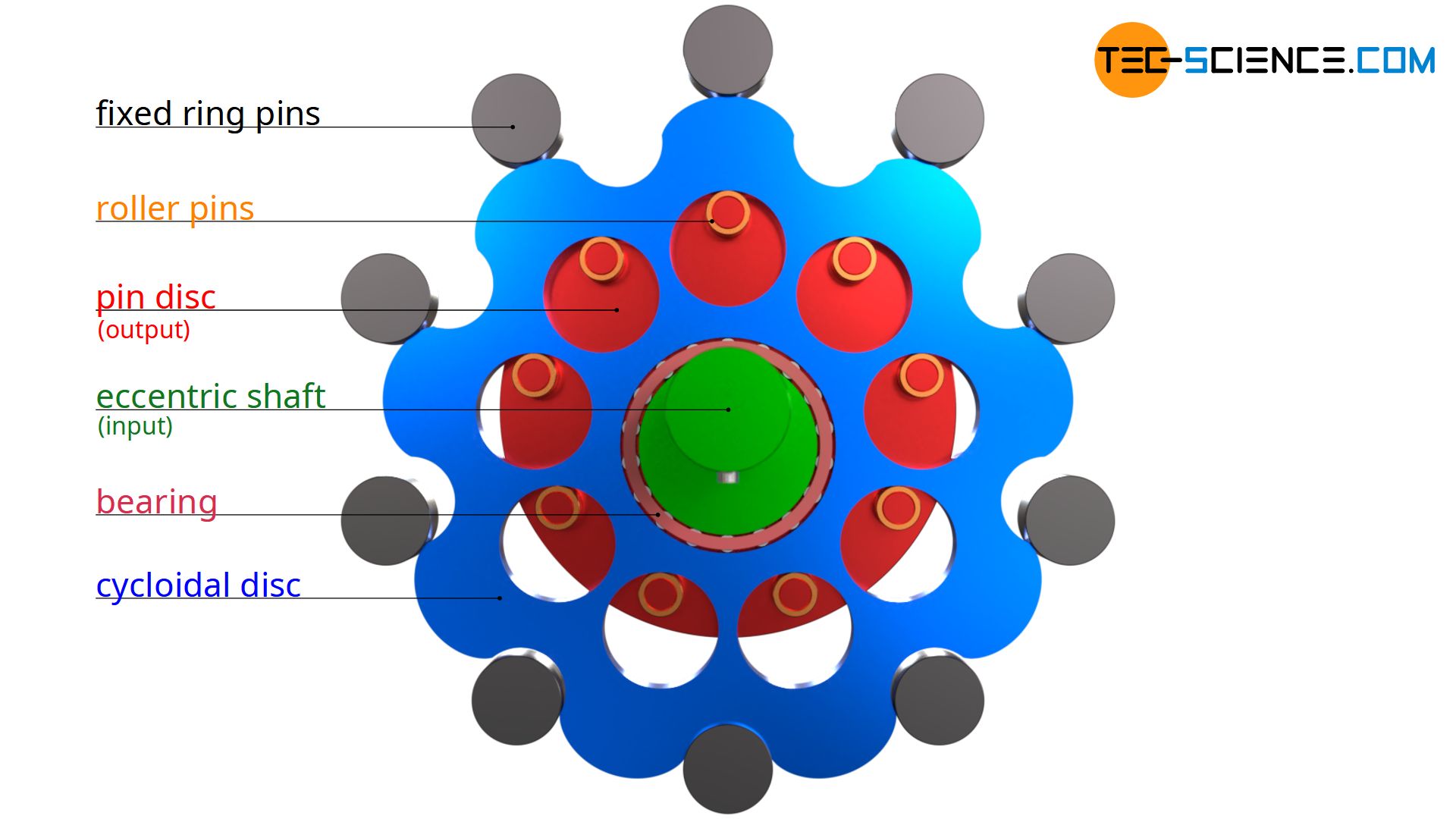
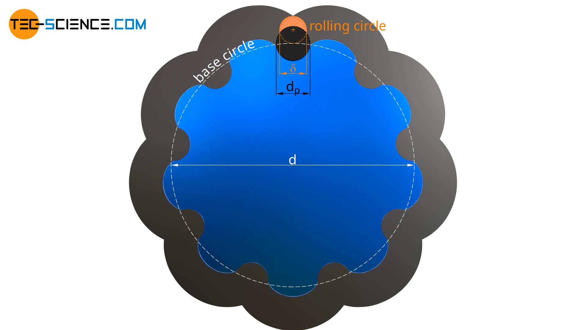
As already explained in the article “Operating principle“, the basic shape of the cycloidal disc is a cycloid. Such a cycloidal shape is obtained by a rolling circle that rolls on a base circle (see also article “Geometry of cycloidal gears“). The cycloid then corresponds to the path described by a point at the circumference of the rolling circle. The resulting cycloidal shape (ordinary cycloid) is referred to as the reference profile.
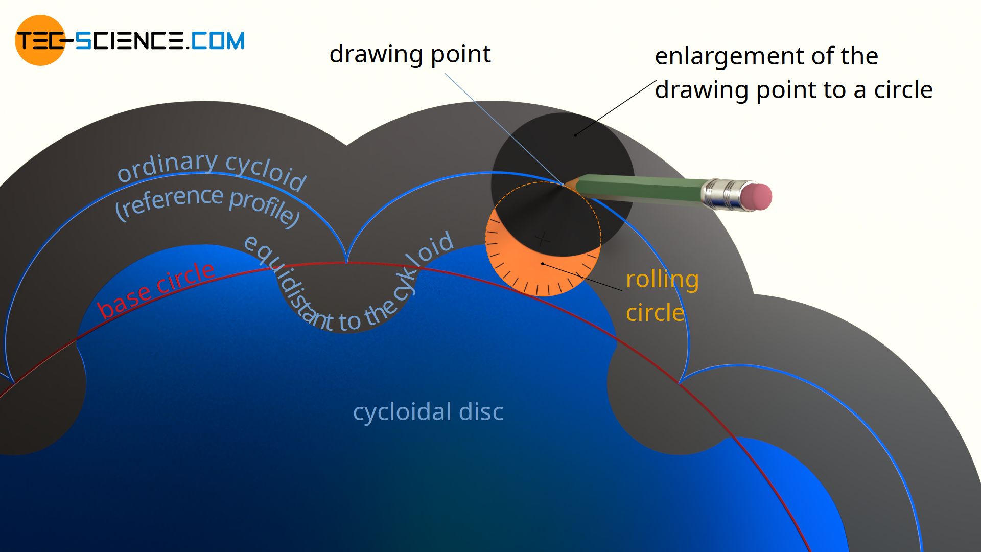
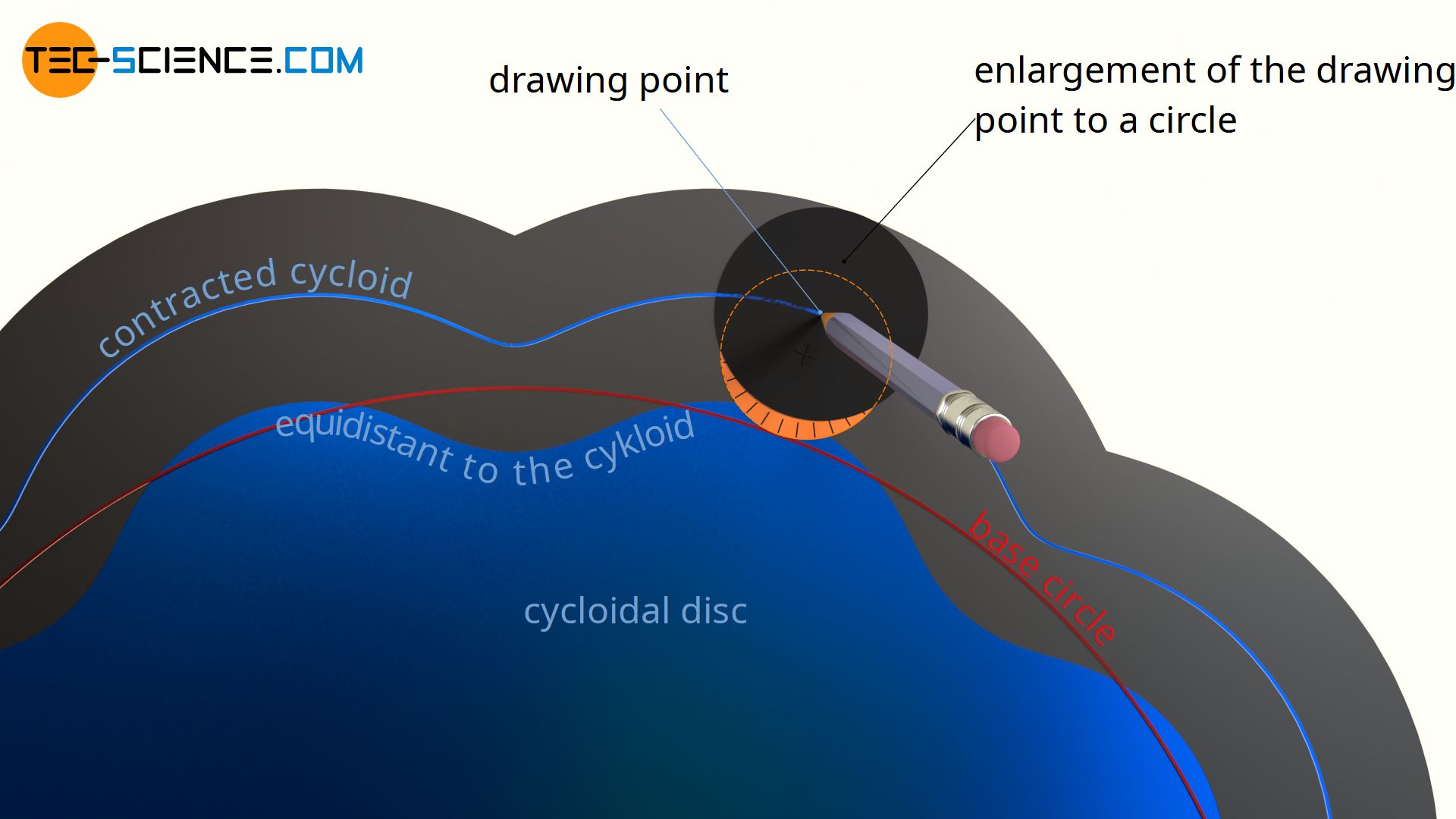
However, it must be taken into account that the cycloidal disc must later roll around the fixed pins. For this reason, the drawing point (“pencil tip”) must be extended to a circle when constructing the cycloid, whereby the diameter of this drawing circle corresponds to the diameter of the fixed pins around which the cycloidal disc later rolls! The enveloping profile that is created when rolling the rolling circle with its drawing circle then corresponds to the actual profile of the dycloidal disc.
The construction of the actual disc profile from the reference profile can also be imagined as follows. If the center of a milling cutter (whose diameter corresponds to the later pin diameter) is placed on the reference profile and milled along that profile, then the actual (equidistant) disc shapeis obtained.
The shape of the cycloidal disc is obtained from an equidistant to the cycloid!
Cycloidal disc with contracted cycloid
The cycloidal disc designed in the previous section has a relatively high eccentricity, which leads to enormous unbalance forces at high speeds and results in an uneven run. The large eccentricity also leads to the fact that the holes in the cycloidal disc are relatively large and therefore close to each other. The low material thickness between the holes could lead to a deformation of the holes at high forces.
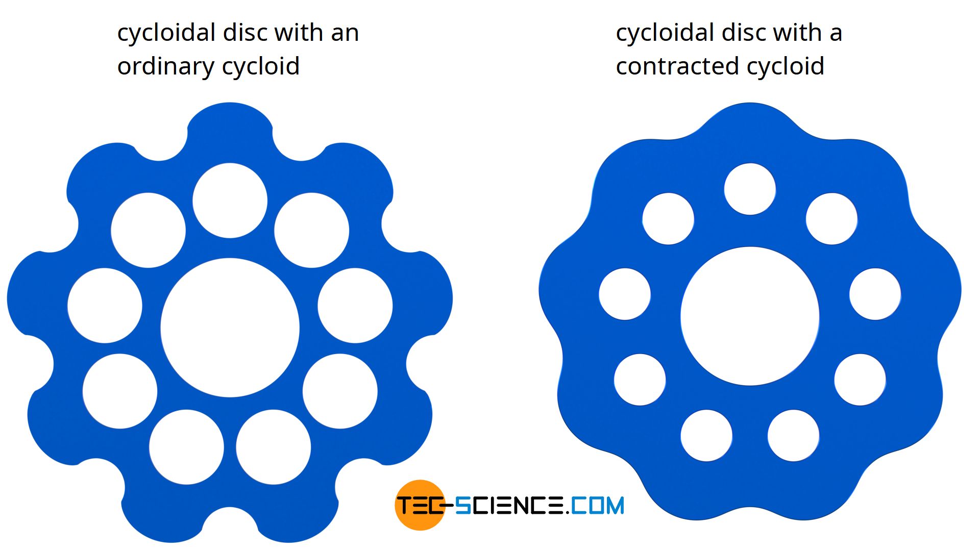
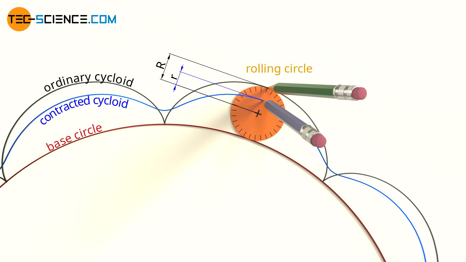
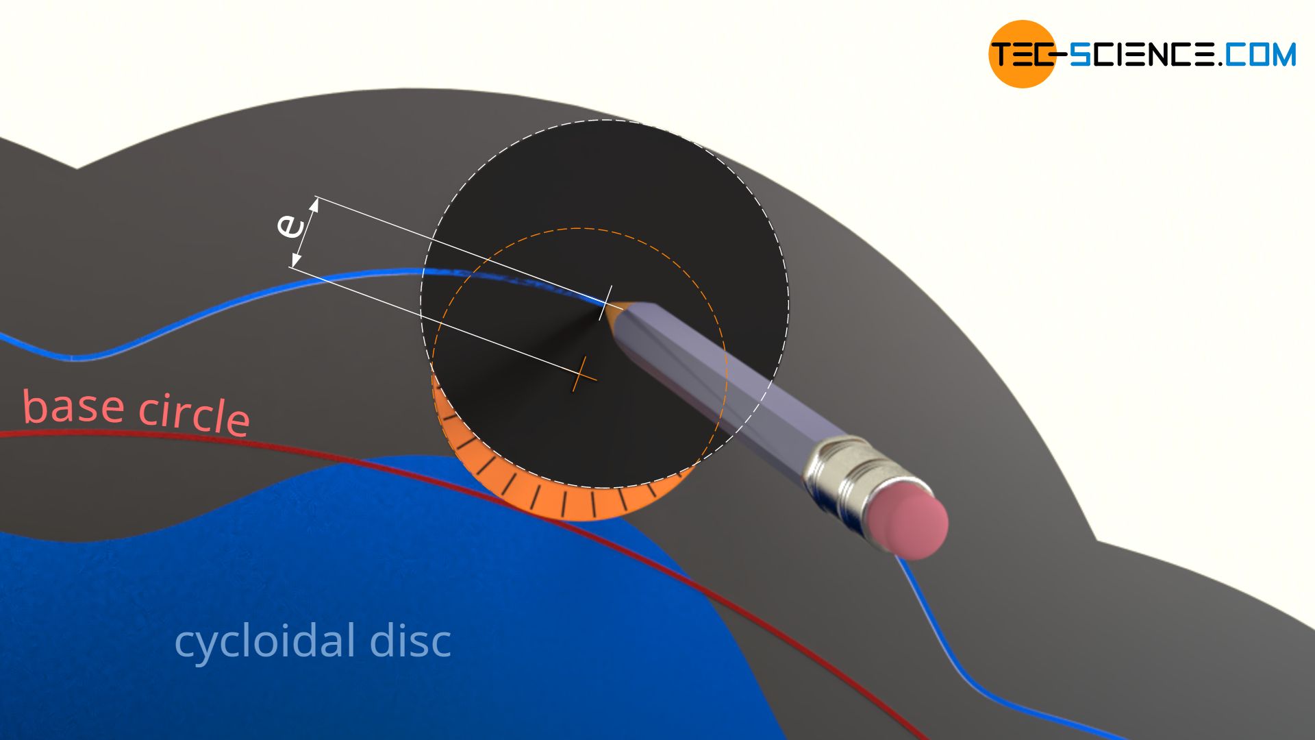
For these reasons, the cycloidal disc is often designed with a so-called contracted cycloid. The drawing point is no longer placed at the circumference of the rolling circle (distance R but is located within the rolling circle (distance r<R). In contrast to this, an extended cycloid is obtained if the drawing point is placed outside the rolling circle (distance r>R). However, the latter has no meaning in mechanical engineering, which is why only the contracted cycloid is used.
The figure below shows the effect of such a contracted cycloid on the shape of the cycloidal disc. The contour of the cycloidal disc is “softer”. Both the eccentricity and the later hole diameters in the cycloidal disc are significantly reduced.
The animation below shows the operation of the cycloidal disc which is constructed with a contracted cycloid.
Note, that the transmission ratio does not change due to the construction with contracted cycloids. The transmission ratio is only determined by the number of lobes n of the cycloidal disc and the number of pins N (for more information see article “Operating principle“):
\begin{align}
&\boxed{i = \frac{n}{N-n} } \\[5px]
\end{align}
The transmission ratio of a cycloidal drive is also reflected in the ratio between the base circle diameter and the rolling circle diameter, which is used to construct the cycloidal disc. From the point of view of the cycloidal disc, it is a matter of rolling the (“fixed”) pins on the cycloidal disc (even if the view as an outside observer is just the other way round: the cycloidal disc rolls on the fixed pins – just a question of perspective).
\begin{align}
\label{2}
&i=\frac{d}{\delta} \\[5px]
\end{align}
Construction of the cycloidal drive
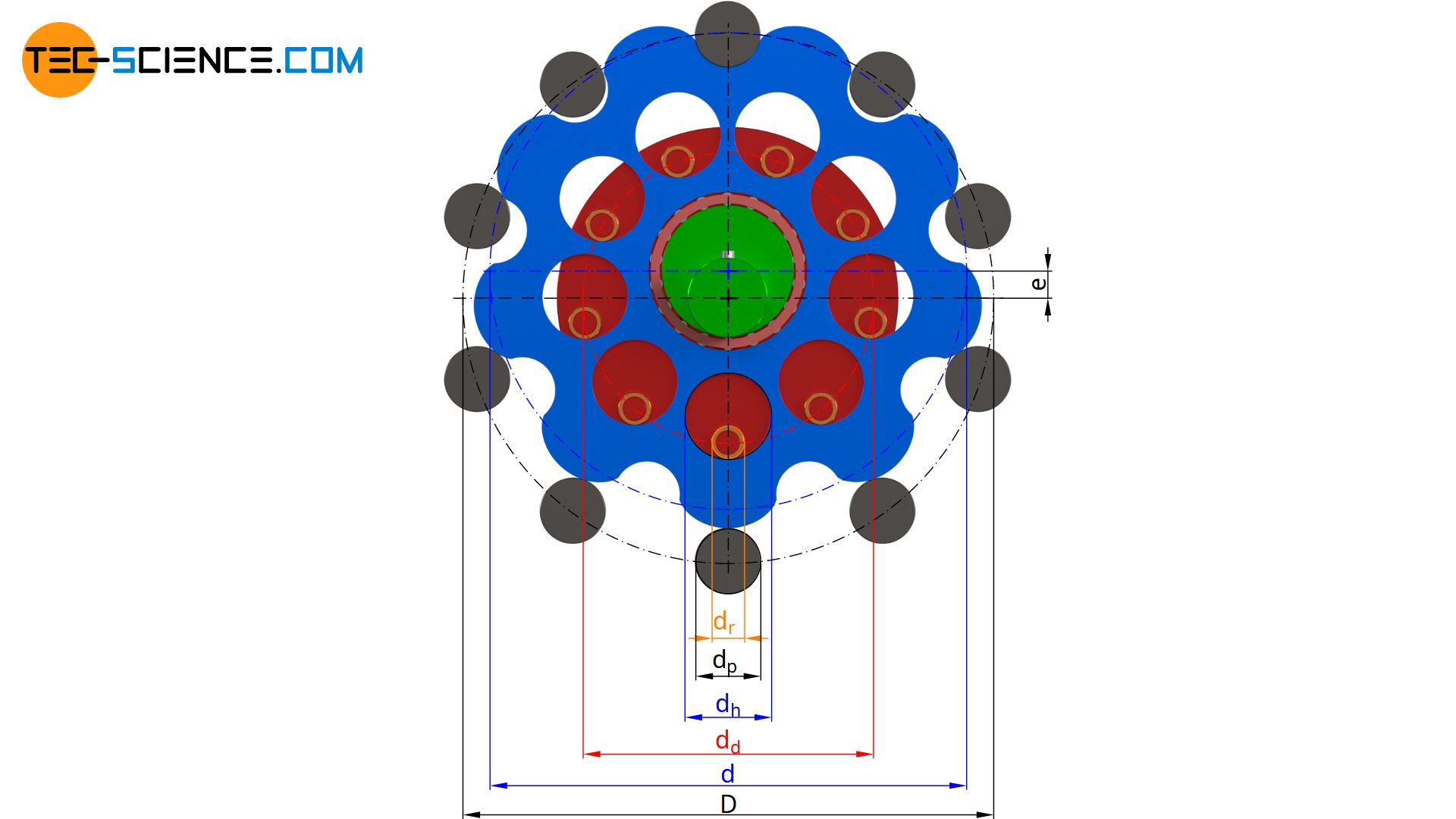
The cycloidal disc shown above will in the following be used to show the determination of the parameters required for the construction of the cycloidal drive. The reference circle on which the fixed pins are arranged is chosen in this case with D = 160 mm. The pin diameter itself is dp = 20 mm. A total of N=10 pins are used, which should lead to a transmission ratio of i = 9. The rollers of the roller disc have a diameter of dr = 14 mm. The rollers themselves are arranged on a reference circle with the diameter dd = 88 mm. The eccentricity of the rotating cycloidal disc is chosen with e = 4 mm.
In principle, the above-mentioned parameters are arbitrary, but should be chosen sensibly. The cycloidal disc can now be constructed using these parameters:
- reference circle diameter of the fixed ring pins D
- pin diameter dp
- number of fixed pins N
- transmission ratio i
- diameter of the roller pins dr
- reference circle diameter dd of the roller pins on the roller disc
- eccentricity of the cycloidal disc e
Diameter of the rolling circle
The diameter of the rolling circle δ for the construction of the cycloidal disc must first be chosen so that the circumference of the rolling circle corresponds exactly to the pin pitch of the fixed pins. This is the only way to ensure that the spacing of the lobes on the cycloidal disc corresponds to the spacing of the fixed pins on the housing and that meshing is possible. Since the respective pitch circle diameter is proportional to the number of lobes or pins, the diameter δ of the rolling circle must therefore be smaller by the number of fixed pins N than the pitch circle diameter D of the fixed pins:
\begin{align}
\label{3}
&\boxed{\delta=\frac{D}{N}}~(= 16 \text{ mm}) \\[5px]
\end{align}
Thus, in combination with equation (\ref{2}), the base circle diameter d for the construction of the cycloidal disc can be calculated as follows:
\begin{align}
&i=\frac{d}{\delta}=\frac{d \cdot N}{D} \notag \\[5px]
\label{4}
&\boxed{d = \frac{i}{N} \cdot D} ~(= 144 \text{ mm}) \\[5px]
\end{align}
Eccentricity
The distance of the drawing point to the center of the rolling circle during the construction of the cycloidal disc corresponds directly to the later eccentricity e, because this distance ultimately determines the “amplitude” with which the drawing circle oscillates around the base circle during the construction of the cycloid. The eccentricity is always smaller or, in extreme cases, equal to half the diameter of the rolling circle.
\begin{align}
&\boxed{e \le \frac{\delta}{2}} \\[5px]
\end{align}
In the present case, the eccentricity was chosen with e = 4 mm. However, the eccentricity should not be too small, as otherwise the shape of the cycloidal disc will become too “soft” and in extreme cases will change into a pure circular shape with an eccentricity of e=0. In this case, of course, a positive fit is no longer possible and even if the eccentricity is too low, there is a risk of the cycloidal disc slipping over the pins.
Hole diameter of the cycloidal disc
The eccentricity e in turn influences the hole diameter dh of the cycloidal disc. On the one hand, the roller pins with the diameter dr must fit through the holes and on the other hand, the holes must take into account the oscillation of the cycloidal disc with the eccentricity e. Therefore, the diameter of the holes dh corresponds to the diameter of the roller pins dr plus twice the eccentricity e:
\begin{align}
\label{exzenter}
&\boxed{d_h = d_r + 2 \cdot e} ~~~~(= 22 \text{ mm}) \\[5px]
\end{align}
The pitch circle diameter on which the holes are arranged around the centre of the cycloidal disc corresponds exactly to the pitch circle diameter on which the rollers are arranged around the centre of the roller disc (dd = 88 mm)!
The geometry of the cycloidal disc or the cycloidal drive is thus completely determined!
")


")