In the Vickers hardness test, a four-sided diamond pyramid is pressed into the material. The indentation surface serves as a measure of the hardness!
For the Vickers hardness test, a square base pyramid with a opening angle of 136° is used as the indenter (opening angle = angle between two opposite surfaces of the pyramid). The angle was chosen so that the Vickers hardness values are comparable to a certain degree with the Brinell hardness values (applies to approx. 400 HBW or 400 HV). The diamond pyramid is pressed into the material surface with increasing force and maintained for about 10 to 15 seconds when the desired test force is reached. As with the Brinell hardness test, the ratio of test force F and indentation surface A (pyramid surface area) serves as hardness value for the Vickers method:
\begin{align}
\label{vickershaerte}
&HV=\frac{0.102 \cdot F}{A} \\[5px]
\end{align}
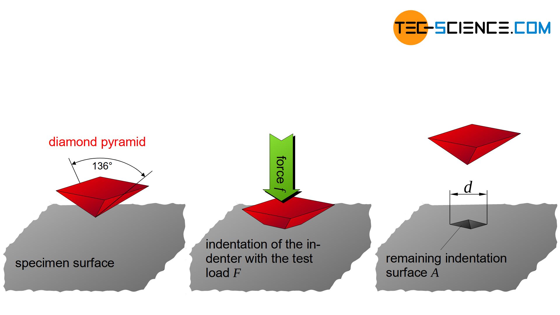
In the Vickers hardness test, a four-sided diamond pyramid is pressed into the material to be tested. The indentation surface left behind serves as a measure of the hardness value!
The factor 0.102 again comes from the no longer used unit “kilopond” (see Brinell hardness test). The indentation surface can be determined from the diagonals of the indentation left behind. With this indentation diagonal \(d\) (in mm) and the test force \(F\) (in N), the Vickers hardness value HV is then determined as follows:
\begin{align}
\label{vickershaertewert}
&\boxed{HV =\frac{0.1891 \cdot F}{d^2}} ~~~~~\text{Vickers hardness} \\[5px]
\end{align}
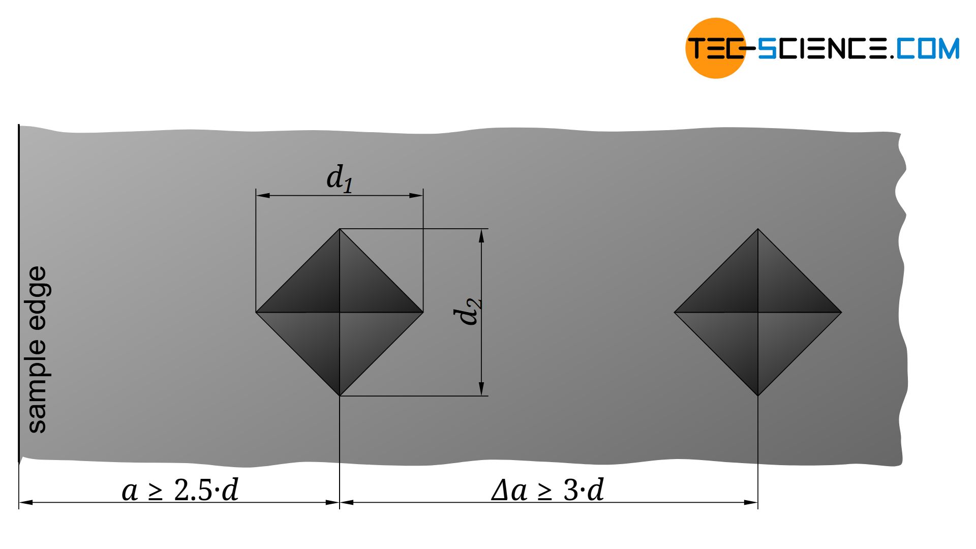
The indentation diagonal \(d\) is determined by the mean value of the two diagonals \(d_1\) and \(d_2\) at right angles to each other:
\begin{align}
\label{durchmesserdiagonale}
&\boxed{d=\frac{d_1+d_2}{2}} \\[5px]
\end{align}
Validity
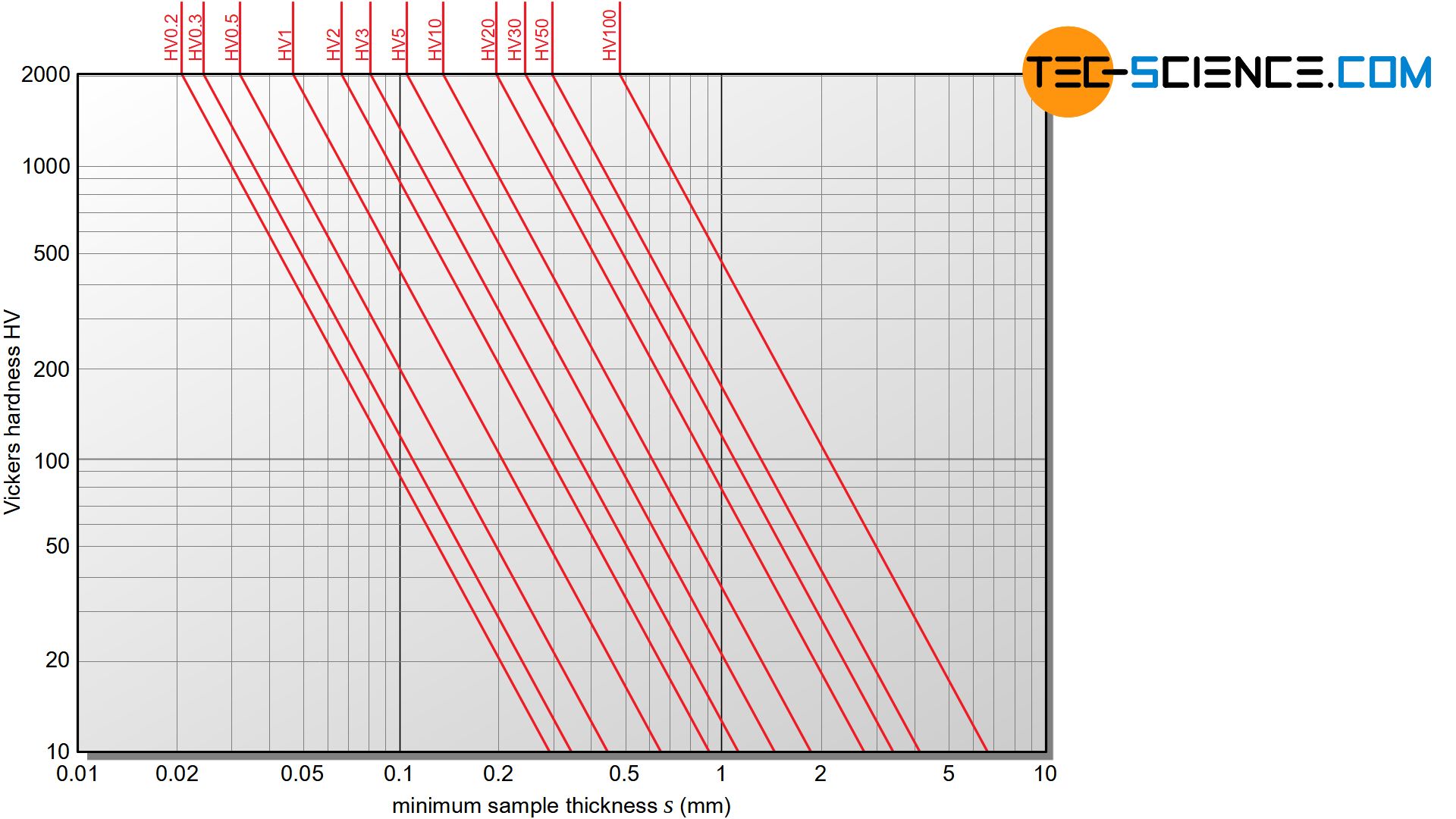
To avoid the risk of material bulging on the opposite side of the sample, the thickness should not fall below a certain minimum value. The minimum thickness depends on the expected hardness of the material and the test load.
In addition, the distance \(a\) from the center of the indentation to the edge of the sample should be at least 2.5 times the value of the indentation diagonal \(d\) to prevent the material from flowing sideways:
\begin{align}
\label{mindestrandabstand}
&\boxed{a \ge 2.5 \cdot d} \\[5px]
\end{align}
Furthermore, the distance between two adjacent indentations for steel and copper samples should be at least as far apart as three times the diagonal length of an indentation (six times for aluminum samples). This is to eliminate the influence of work hardening phenomena around the area of the indentation.
\begin{align}
\label{mindestprobenabstand}
&\boxed{\Delta a \ge 3 \cdot d} \\[5px]
\end{align}
Comparability of hardness values
In contrast to a ball (as in Brinell hardness test), a pyramid always provides to a certain extent geometrically similar indentations even with different test loads. Thus, with identical samples, the double force also leads to a double indentation surface. As a ratio of force and indentation surface, the hardness value is therefore always identical despite different test loads*. However, the independence of the hardness value from the test load does not apply to low test loads. In this case, the elastic deformation accounts for a larger proportion of the total deformation. As a result, the remaining pyramid indentation is smaller and thus pretends a higher hardness value.
*) This is not the case with Brinell hardness test. There the double force (higher load factor) would lead to a different hardness value for the same ball used.
Therefore, Vickers hardness values should only be compared with each other if they were determined with the same test loads. A harder material always requires higher test loads than a softer material. Depending on the expected hardness of the material, different test load ranges are prescribed. A distinction is made between three ranges of loads.
On the one hand, the so-called macro test range with test loads between 49.03 N (5 kp) and 980.7 N (100 kp), within which the hardness values are practically independent of the test load (“macrohardness”).
On the other hand, the micro test range is differentiated between 1.961 N (0.2 kp) and 29.42 N (3 kp). Such a load range is used for thin surface layers and sheet metals as well as for finished parts in order not to damage the components too much (“microhardness”).
In special cases, the nano test range between 0.098 N (0.01 kp) and 1.961 N (0.2 kp) is also used (“nanohardness”). The pyramid tip used offers an additional advantage over the ball in the Brinell process, since the pyramid-shaped indentation leaves sharper edges even at low indentation depths and can thus be better measured. At low indentation depths, therefore, the accuracy of the Vickers test increases compared to the Brinell hardness test.
In contrast to the Brinell hardness test, the Vickers test method is suitable for all hardness ranges, i.e. from very soft to very hard materials. In addition, this method can also be used for thin sheets or thin surface layers, which makes it a universal hardness testing method.
The Vickers hardness test is suitable for soft to very hard materials and especially for thin sheets!
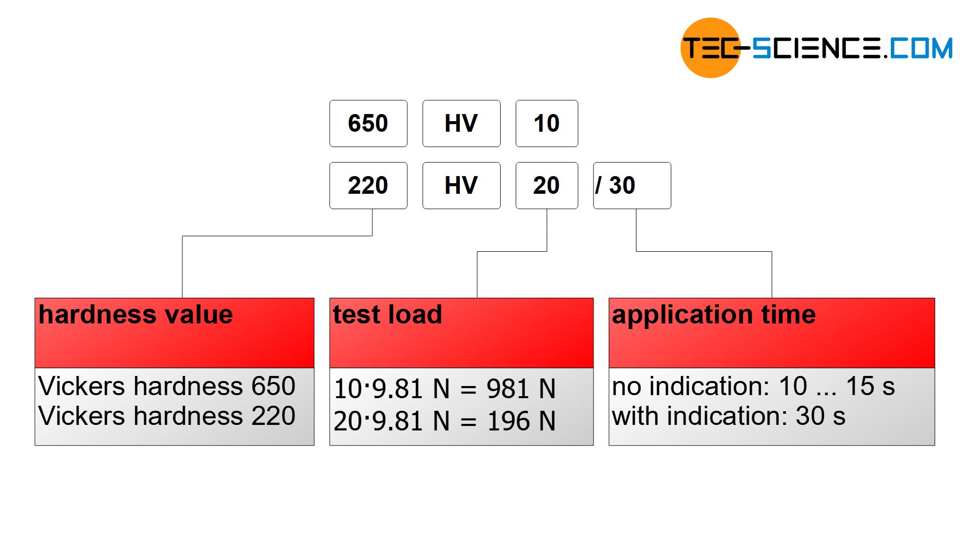
Indication of the hardness value
The standard-compliant specification of Vickers hardness consists of the hardness value, the test force and the application time. The latter can be omitted with the standard time of 10 to 15 seconds.
Both the Brinell and Vickers hardness test use the indentation surface left behind as a hardness measure. The indentation geometry is determined by a light microscope. This usually requires a glossy surface so that the indentation is clearly visible. It may be necessary to polish the sample before testing. Therefore, these processes are generally not suitable for automated production. For this reason, the Rockwell hardness test was developed.


")
")
")
")