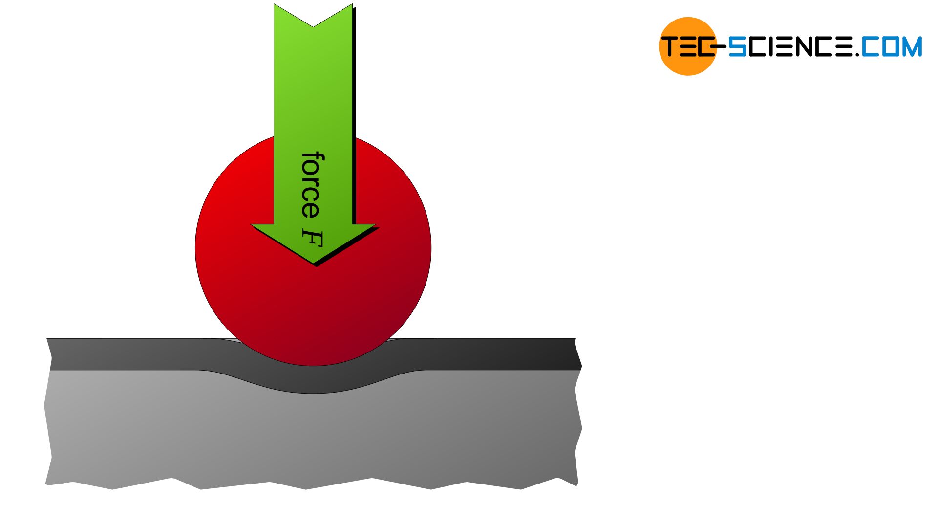
With the Brinell hardness test, a carbide ball is pressed into the material. The indentation surface serves as a measure of the hardness!
Introduction
In many applications, components should have not only a high strength but also a high wear resistance. This generally applies whenever two or more components are in moving contact with each other. These include, for example, gears, shafts, bolts, pins, etc.
High wear resistance ultimately means a hard surface, so that the surface is not damaged in contact with adjacent components and thus wear is kept to a minimum. For this reason, characteristic values are required to characterize the hardness of a material. In order to obtain such parameters, hardness must first be defined:
Indentation hardness is the resistance of a material to penetration by an indenter (indentation resistance)!
According to this definition, all hardness testing methods are ultimately based on the same principle. An indenter (e.g. ball, cone, pyramid, etc.) is pressed with a certain force into the material surface to be tested. The indentation hardness value is determined from the indentation left behind.
Depending on the material to be tested and the given boundary conditions, different hardness tests have developed, whose respective measured values generally cannot be converted into one another. Therefore, hardness values can only be compared if they have been obtained by identical test procedures. The most important procedures and their advantages and disadvantages are explained in more detail below:
- Brinell hardness test (explained in this article)
- Vickers hardness test
- Rockwell hardness test
Specially prepared specimens or real components can be used for hardness testing, provided that their functionality is not impaired due to the indentation left behind.
Determination of the hardness
In Brinell hardness testing, a hard metal ball (carbide ball) is pressed into the material surface to be tested within approximately 10 seconds as the force increases. The applied test force is maintained for 15 to 20 seconds so that the material can settle during this time and the measurement provides reproducible and comparable test results. The indentation left behind on the material surface is then determined under a light microscope. The ratio of testing force \(F\) and the indentation surface \(A\) (spherical segment) serves as a measure for the Brinell hardness value HBW:
\begin{align}
\label{brinellhaerte}
&HBW=\frac{0.102 \cdot F}{A} \\[5px]
\end{align}
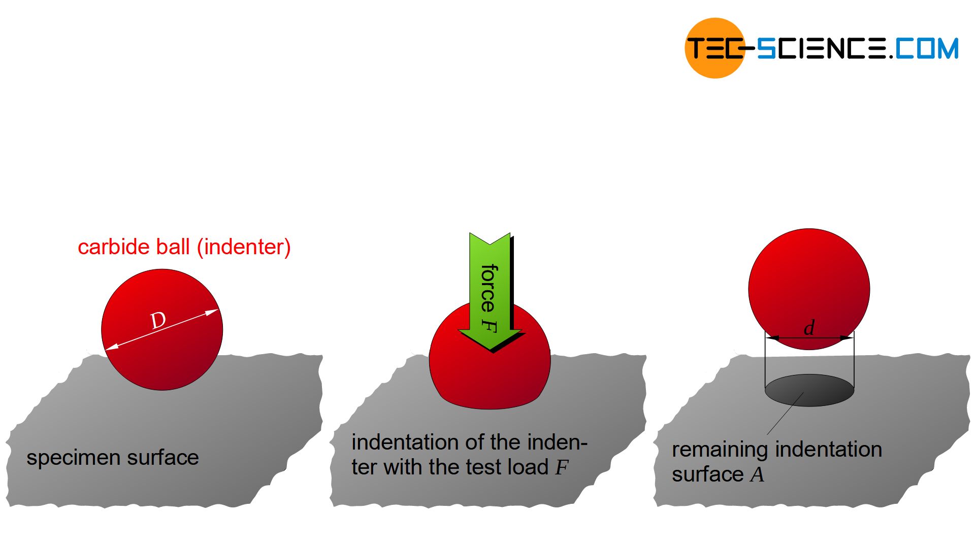
With the Brinell hardness test, a carbide ball is pressed into the material. The indentation surface left behind serves as a measure of the hardness!
The factor 0.102 in the equation is due to the unit “kilopond” or “kilogram-force” (1 kp ≙ 9.807 N), which was used in the past but is no longer permissible today. Therefore, the unit kilopond was replaced by the physically correct unit “Newton” with the corresponding conversion factor of 0.102 (=1/9.807).
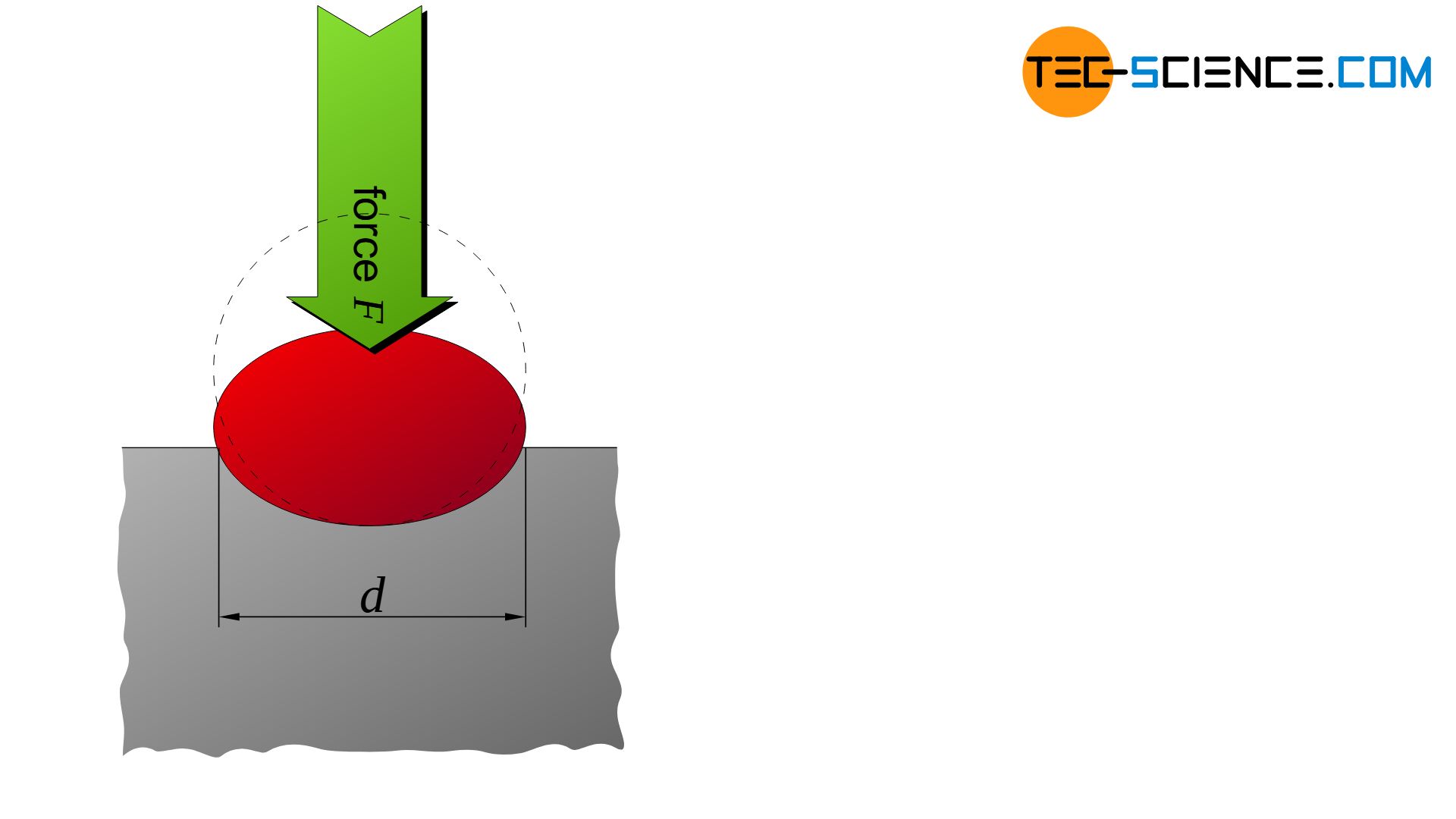
The indentation surface \(A\) can be determined by the diameter \(D\) of the penetrator ball and by the indentation diameter \(d\) left behind using the following formula:
\begin{align}
\label{kugelsegment}
&A=\frac{\pi}{2} \cdot D \cdot \left(D-\sqrt{D^2-d^2} \right) \\[5px]
\end{align}
By combining equation (\ref{kugelsegment}) and equation (\ref{brinellhaerte}), the unit-less Brinell hardness HBW is calculated as a function of the applied penetration force \(F\) (in N) and the ball diameter \(D\) (in mm) and the indentation diameter \(d\) (in mm) as follows:
\begin{align}
\label{brinellhaertewert}
&\boxed{HBW =\frac{0.204 \cdot F}{\pi \cdot D \cdot \left(D-\sqrt{D^2-d^2} \right)}} ~~~~~\text{Brinell hardness} \\[5px]
\end{align}
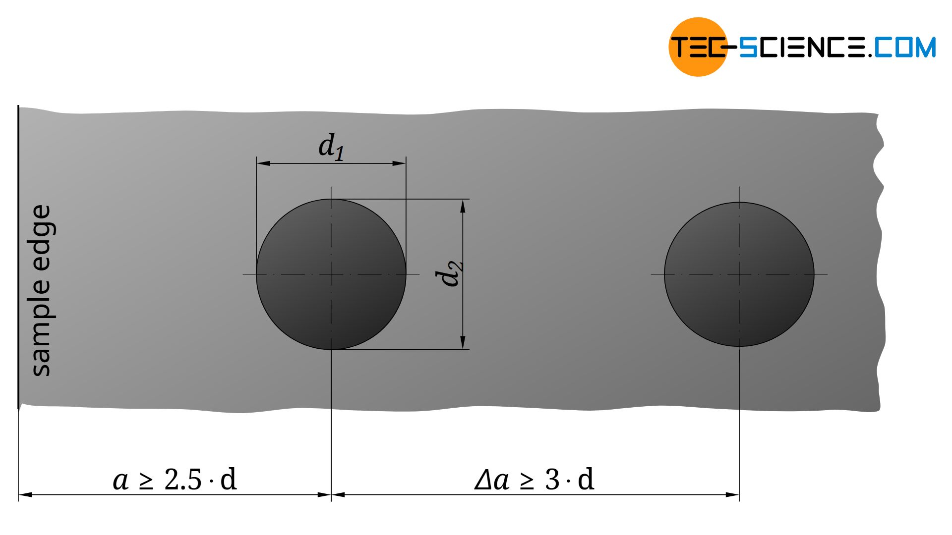
Due to the anisotropy in the deformation behavior, it can happen that there is no exactly circular imprint on the material surface. Then the indentation diameter \(d\) is determined from the mean of two indentation diameters \(d_1\) and \(d_2\) at right angles to each other:
\begin{align}
\label{durchmesser}
&\boxed{d=\frac{d_1+d_2}{2}} \\[5px]
\end{align}
Validity
To prevent the material from being pushed over the edge of the specimen during testing and therefore pretending a lower hardness value, the center of the indentation should be at least as far from the edge as 2.5 times the diameter of the indentation.
\begin{align}
\label{mindestabstand}
&\boxed{a \ge 2.5 \cdot d} \\[5px]
\end{align}
If several hardness tests are carried out on one single specimen, care must be taken to ensure that the indentations do not fall below a minimum distance from each other. Otherwise, the measurement result would be influenced by hardening phenomena that occur around the respective indentations. This distance should not be less than 3 times the indentation diameter.
\begin{align}
\label{mindestabstand_proben}
&\boxed{\Delta a \ge 3 \cdot d} \\[5px]
\end{align}
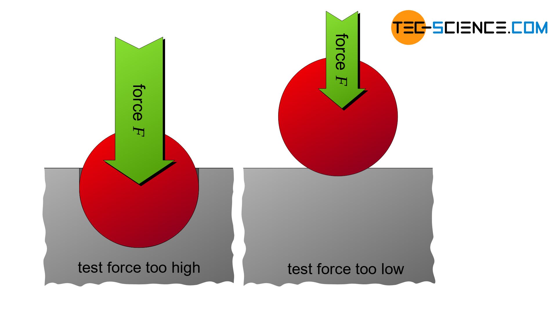
In order to obtain comparable results, the indentation diameter \(d\) should not be smaller than 24 % and not larger than 60 % of the indenter diameter \(D\):
\begin{align}
\label{mindestdurchmesser}
&\boxed{0.24 \cdot D \le d \le 0.6 \cdot D} \\[5px]
\end{align}
If the indentation diameters are too large and lie in the range of the test ball diameter, the test ball is pressed too deeply into the material. A further penetration then hardly produces a larger indentation diameter, which then leads to no longer reproducible hardness values due to measurement inaccuracies in the diameter determination.
If, on the other hand, the indentation diameter is too small compared to the test ball diameter used, however, the ball is hardly pressed into the material. Blurred edges are the result, from which it is very difficult to determine the indentation diameter left behind. Due to the low deformation, elastic portions are particularly high, so that the indentation diameter decreases relatively strongly when the ball is lifted off. The hardness values obtained from small indentation diameters are no longer valid, as well as those from large diameter values.
Load factor
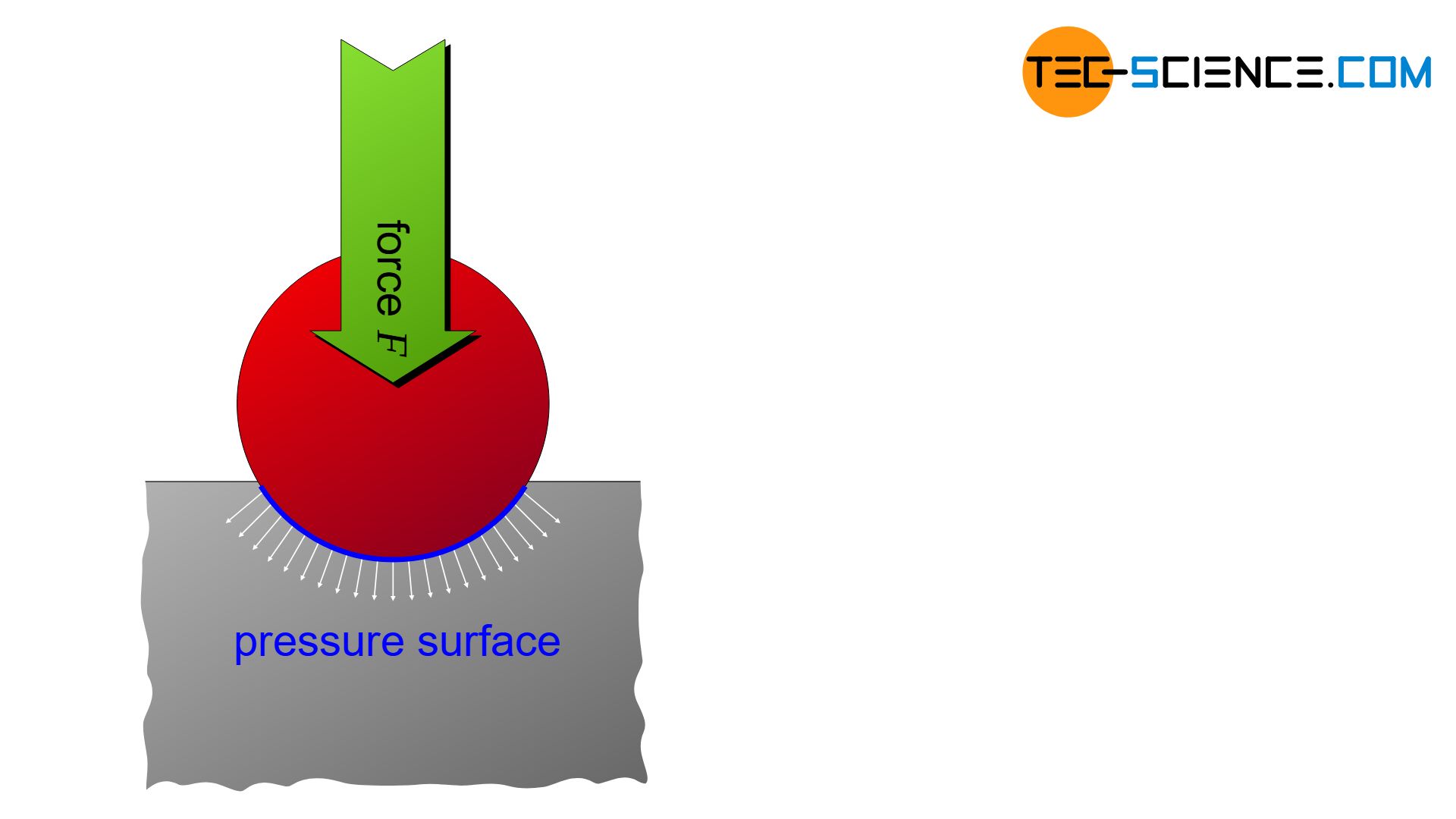
For the above mentioned reasons of too much or too little penetration, the surface pressure between the ball and material sample must therefore not be too high and not too low. Comparable results for different materials are only given if the test was carried out with the same stress intensity. Due to the larger surface area, larger test balls also require higher test forces compared to smaller test balls, in which the forces are distributed over a smaller surface.
In order to do justice to this fact, the so-called load factor \(B\) is defined. The load factor is ultimately defined by the ratio of test load to test ball surface and can be regarded as a kind of “surface pressure”:
\begin{align}
\label{beanspruchungsgrad}
&\boxed{B =\frac{0.102 \cdot F}{D^2}} ~~~~~\text{load factor} \\[5px]
\end{align}
For comparability of the hardness values obtained with different test balls on different materials, the load factor \(B\) must have the same value in all cases!
The factor 0.102 results again from the obsolete unit “kilopond”. In contrast to softer materials, hard materials must be tested with a higher load and thus with a higher load factor in order to maintain the diameter range according to the equation (\ref{mindestdurchmesser}).
The load factor is standardized to the values 1 – 2.5 – 5 – 10 – 15 – 30. Depending on the expected hardness, reference values for the load factor used can be found in the table books. The test force \(F\) (in N) to be set can then be determined with equation (\ref{beanspruchungsgrad}) depending on the dimensionless load factor \(B\) and the selected ball diameter \(D\) (in mm).
Test balls
Sintered carbide balls with a standardized diameter of 10 mm, 5 mm, 2.5 mm, 2 mm or 1 mm are available as test balls for Brinell hardness testing. Small diameters are necessary for thinner sheets, as balls that are too large would only bulge out the material on the opposite side of the sheet. In principle, the sample thickness \(s\) should be at least 8 times the penetration depth \(h\):
\begin{align}
\label{mindestprobendicke}
&\boxed{s \ge 8 \cdot h} ~~~~~\text{minimum thickness of the sample} \\[5px]
\end{align}
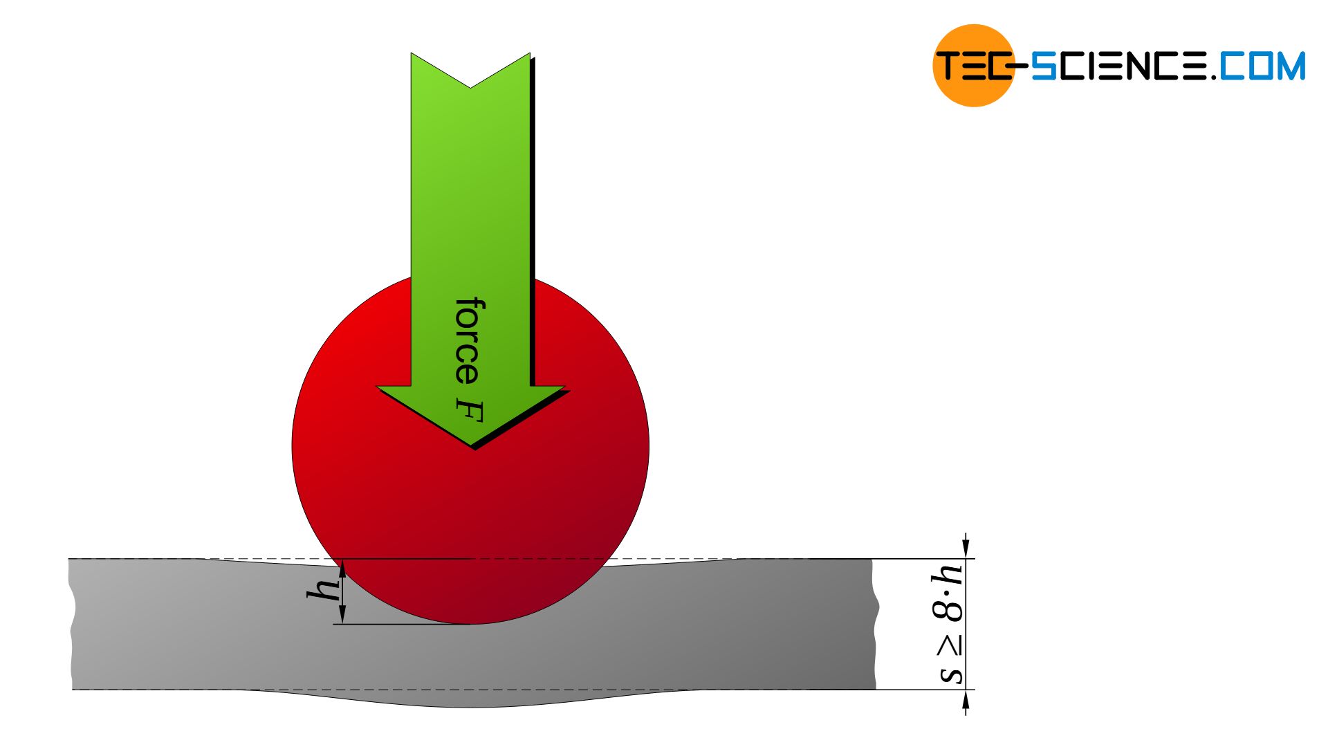
Large test balls are also not suitable for determining the hardness of thin surface layers. In such cases, there is a risk that the surface layer will only be pressed into the underlying base material.
Larger ball diameters are necessary when testing coarse-grained, heterogeneous microstructures (e.g. cast iron). Due to the large sphere, as many individual (heterogeneous) structural components as possible are involved in the deformation, resulting in a hardness value that covers the entire microstructure and not just individual phases. This testing of heterogeneous microstructures is a big advantage of Brinell hardness testing. In principle, however, it is only suitable for soft to medium-hard materials.
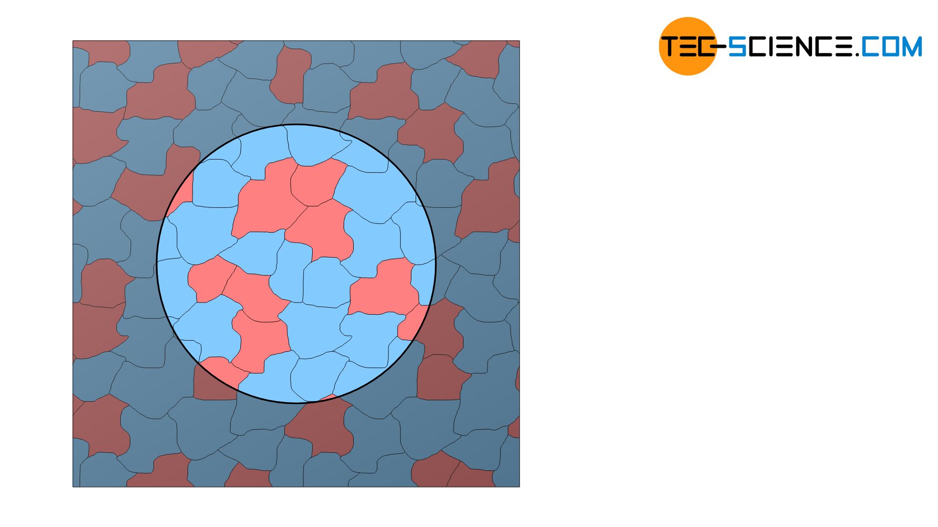
Brinell hardness testing is particularly suitable for thicker, heterogeneous materials in the low to medium hardness range! Thin sheets cannot be tested with the Brinell hardness test!
The Brinell hardness test is not suitable for very hard materials or hardened surface layers because the ball does not penetrate sufficiently into the material. Higher test loads are not the solution at this point, as this leads to deformation of the carbide ball. The flattening of the ball results in a larger indentation diameter and thus pretends a softer material.
Even very thin sheets cannot be tested due to the aforementioned bulging of the material on the opposite side of the sheet. In order to close this gap, a new hardness test method was developed by Vickers, which is explained in a separat article.
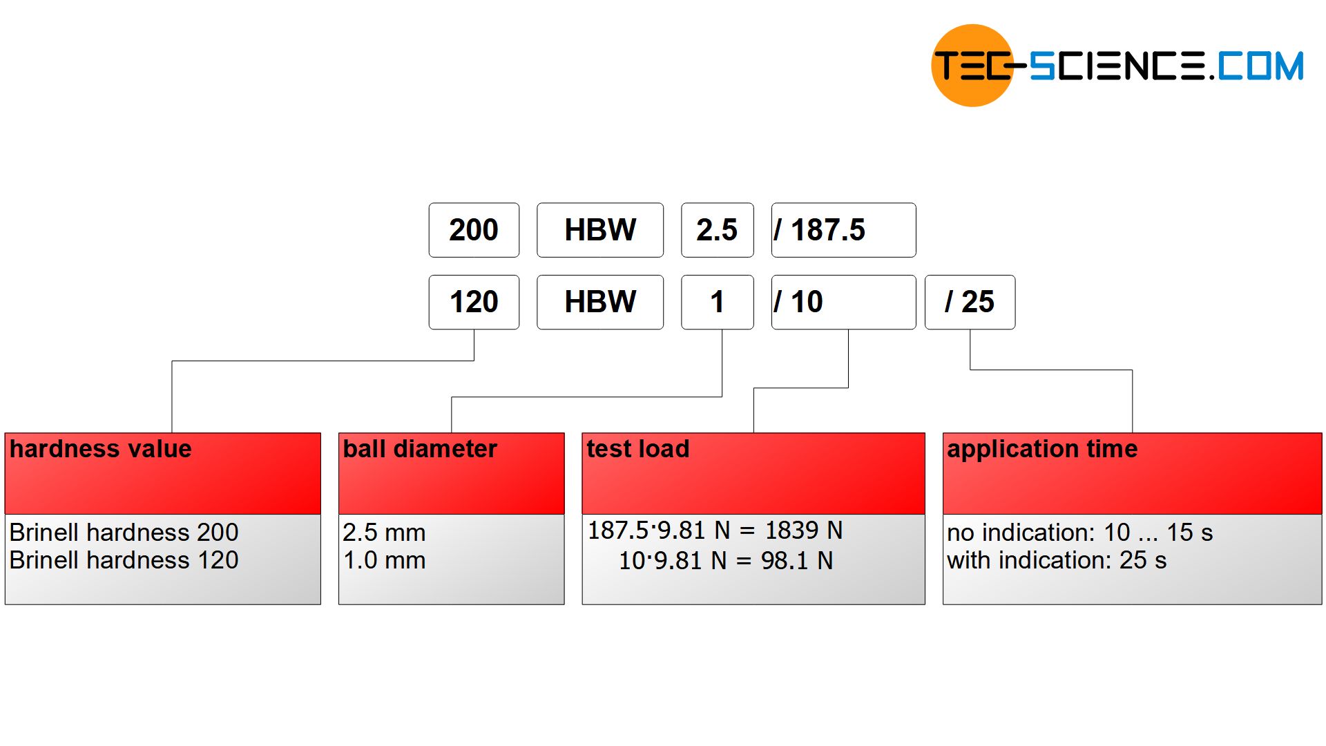
Indication of the hardness value
The standard-compliant specification of Brinell hardness consists of the hardness value (HBW), the ball diameter (in millimeters), the test force (in kiloponds) and the application time (in seconds). These values are given without units and separated by slashes. The indication of the time can be omitted if the test was performed with the standard application time of 10 to 15 seconds.
Empirical relationship between tensile strength and hardness for non-alloy steels
For unalloyed and low-alloyed steels there is an empirical relationship between the Brinell hardness HBW and the tensile strength \(\sigma_u\). This relationship means that the tensile strength (in N/mm²) corresponds approximately to 3.5 times the Brinell hardness value:
\begin{align}
\label{zugfestigkeit_brinell}
&\boxed{R_m \approx 3.5 \cdot \text{HBW}} \\[5px]
\end{align}


")
")
")
")