With magnetic particle inspection (MPI), surface defects such as cracks of ferromagnetic components are made visible.
Introduction
Like the dye penetrant inspection, magnetic particle inspection is also a method for examining surface defects such as cracks. In contrast to the dye penetrant inspection, flaws near the surface that do not reach directly to the surface can also be localized. Magnetic particle testing can only be applied to ferromagnetic materials and is based on the principle of deflecting magnetic field lines at defects. A distinction is made between two inspection methods, which are explained in more detail below:
- magnetic field flow method
- current flow method
Magnetic field flow method
First, the component to be examined is thoroughly cleaned and the test site magnetized with a yoke. Magnetic field lines are formed in the component between the ends of the yoke. In the crack-free state, the field lines run in a straight line and parallel to each other near the surface.
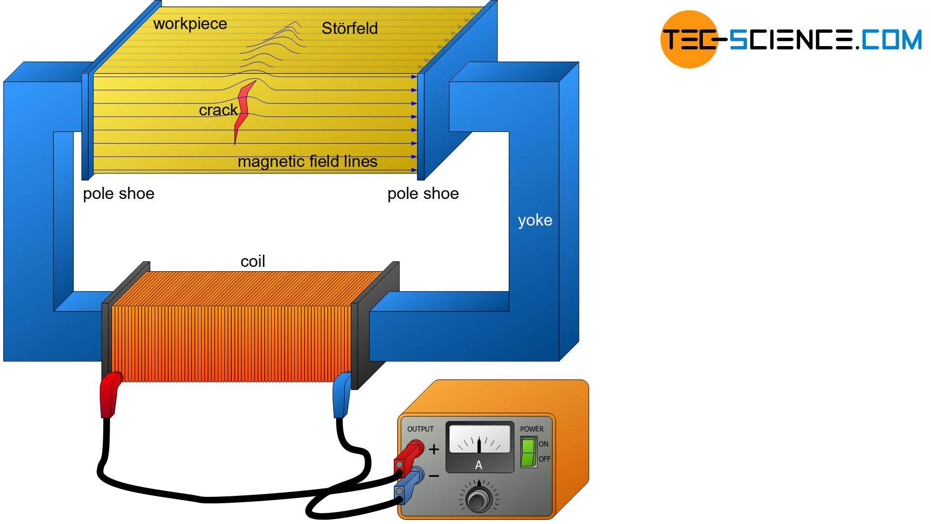
However, at imperfections such as cracks, a stray magnetic field is created, which causes the magnetic field lines to be increasingly forced out of the interior of the workpiece. In this area, there is a particularly large magnetic effect on the surface. Iron particles applied to the surface therefore adhere well to these imperfections.
After magnetization, a ferromagnetic iron oxide powder is applied as test medium, which is mixed with an oil-based fluorescent carrier liquid (test suspension). By adding the fluorescent agent, the flaws can be made particularly visible under ultraviolet light.
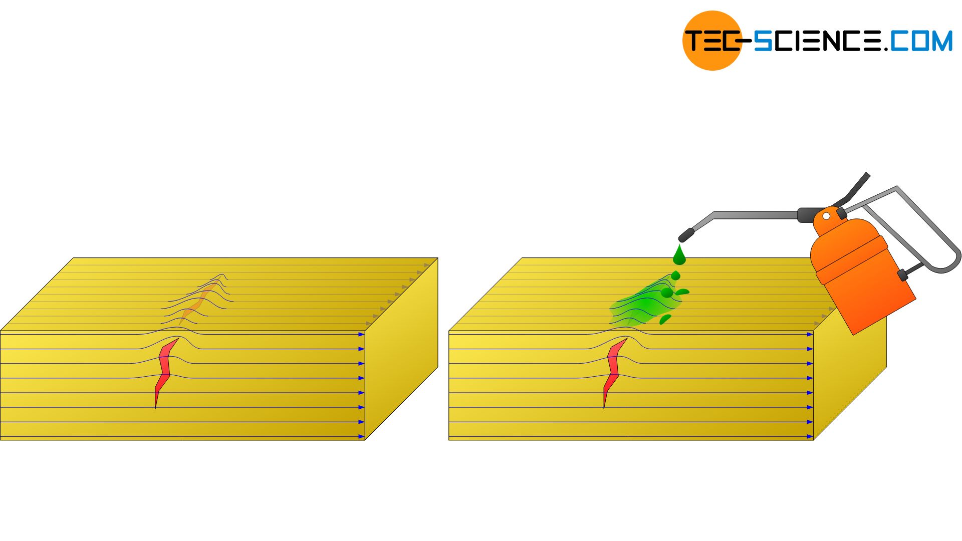
For optimum flaw resolution, the defect should be aligned perpendicular to the magnetic field lines so that the effect of a magnetic stray field is as large as possible. Elongated Cracks that are parallel to the magnetic field direction, however, can hardly be made visible due to the low scattering effect. However, in order to detect even such unfavourable defects, the test benches can be switched to the current flow mode at the touch of a button. This method will be explained in more detail in the next section.
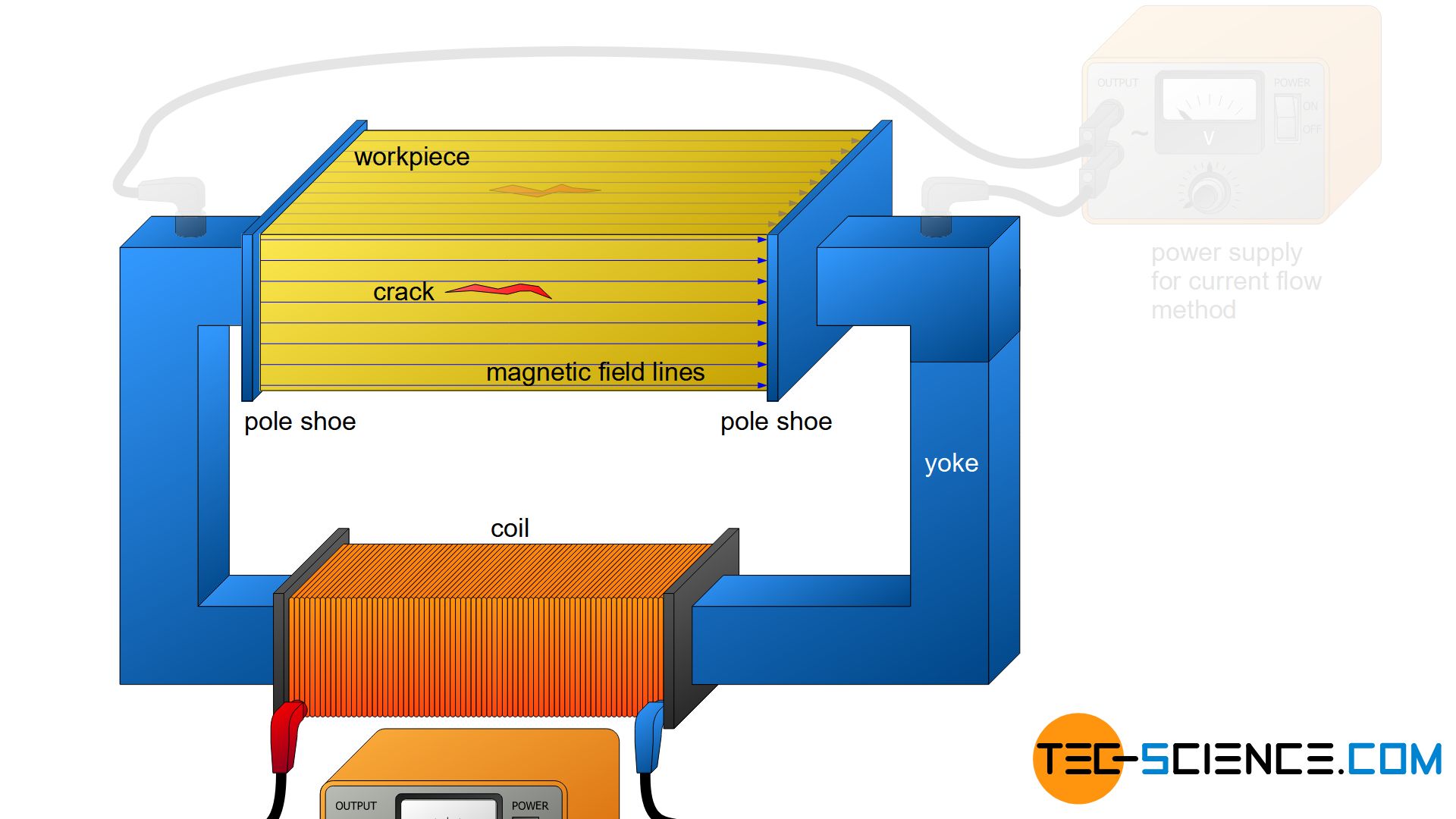
Current flow method
Instead of “flooding” the workpiece directly with a magnetic field, a current flow is first generated in the workpiece. For this purpose, an electric field is introduced via the yoke instead of a magnetic field. Due to the electrical conductivity of the metallic workpiece, an electrical current is generated. This current flow in turn causes a magnetic field whose field lines form concentrically to the current flow (“magnetic field of a current-carrying wire”).
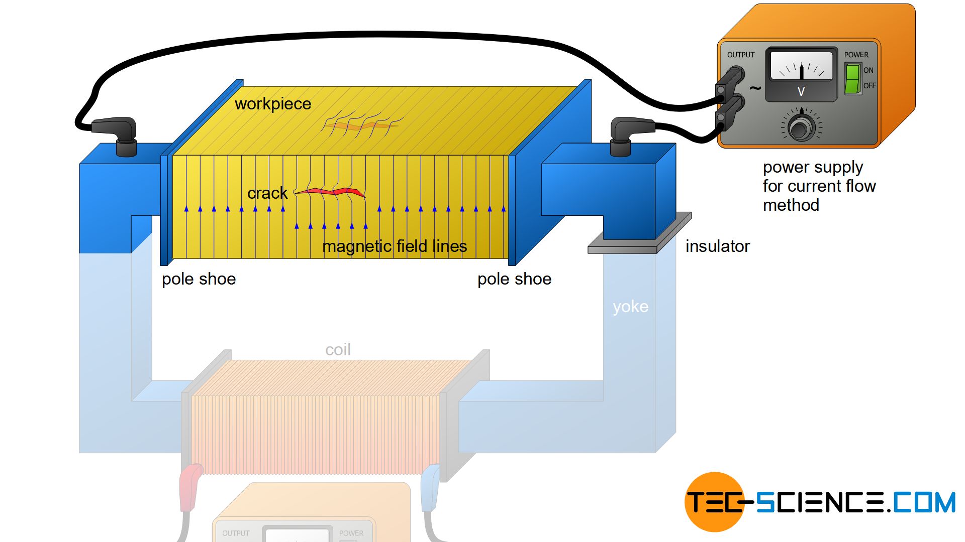
Compared to the magnetic flow method, the magnetic field is now perpendicular aligned to it, so that even the previously unfavourably oriented flaws can now be optimally resolved.


")
")
")