Ultrasonic testing uses sound waves to non-destructively inspect a component for flaws.
Introduction
Ultrasonic testing is a non-destructive testing technique because the workpieces or components to be tested are not damaged during the test. If there are no complaints after the test, the component can continue to be used. Ultrasonic tests are therefore often used for weld inspections.
The most common form of ultrasonic testing is based on the pulse-echo method. Acoustic waves in the ultrasonic range with typical frequencies between 0.2 MHz and 100 MHz are induced pulse-like into the workpiece to be tested by a probe. The pulse duration is usually a few microseconds. These sound pulses propagate in the workpiece with characteristic sound velocity (depending on the material). At locations where the propagation speed of the ultrasonic pulses changes, the sound waves are reflected. This is then referred to as an echo.
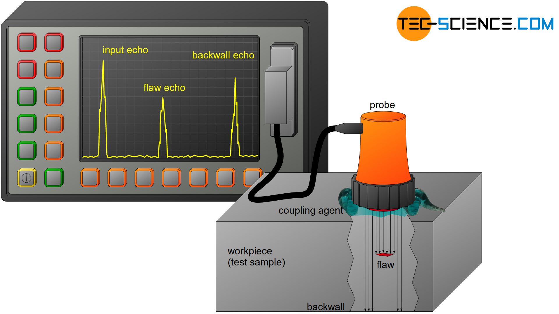
Echoes occur particularly at imperfections such as pores, cavities or cracks, since the speed of sound in the metal structure is approximately 10 to 20 times higher than that of air. Such reflection points are also referred to as reflectors. In contrast to flaw echos (or defect echos), reflections also occur on the rear wall of the test material (backwall echo).
The sound pulses reflected from the backwall or from imperfections are registered by a receiver. From the elapsed time between emission of a sound pulse and registration of a flaw echo, the location (depth) of the echo point and thus the position of the imperfection can be determined, provided that the propagation speed of the sound waves is known (depending on the material). It should be noted that the measured time results from twice the distance until the echo location is reached, since the sound pulse needs the same time for the return path after reflection.
In ultrasonic testing, sound pulses are passed through the workpiece, which are reflected at imperfections (flaw echo). In this way, defects can non-destructively be localized!
In order that the probe can induce the ultrasonic pulses into the workpiece and the entire sound pulses are not already reflected on the outside of the test material (input echo), the entire area of the probe must rest completely on the workpiece surface. However, due to the surface roughness of each workpiece or probe, this is not easily possible. For this reason, a gel-like coupling agent is applied to the workpiece. This completely wets the surface of the probe and the workpiece, thus enabling the sound pulses to be emitted and received again with low reflection. In order to achieve the necessary coupling effect in special automated processes, the entire component can also be immersed in water.
Coupling agent is used to introduced the ultrasonic waves into the workpiece with low reflection and to receive them again with low reflection!
When inspecting workpieces, the probes used are particularly important and must be carefully selected depending on the application. In order to better understand the different requirements on the probes, the generation and propagation of ultrasound is described in the next sections.
Generation and reception of ultrasound
The principle of ultrasonic generation is based on the piezoelectric effect. Historically, piezoelectricity was first discovered on quartz (silicon dioxide, \(SiO_2\)). It was found that mechanical stress (compressive or tensile stress) leads to a shift of the charge concentrations in the atomic structure of the quartz. Electric dipoles are formed, which lead to a voltage between the top and the bottom of the quartz. Not only silicon dioxide but also many other materials such as artificially produced ceramics show a piezoelectric effect. Such materials are generally referred to as piezoelectric crystals.
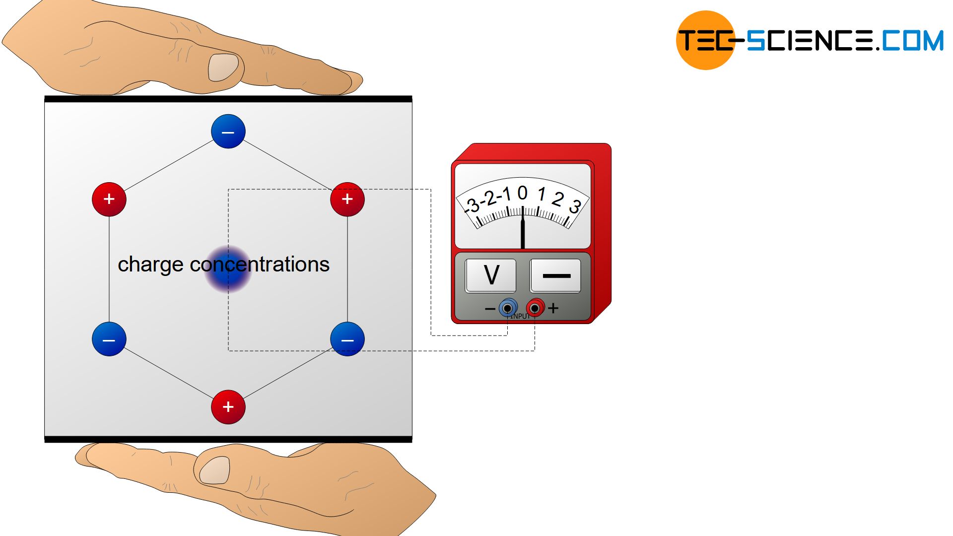
The piezoelectric effect is the generation of a voltage by mechanical deformation of certain materials (piezoelectric crystals)!
The piezoelectric effect can also be reversed! This means that when an external voltage is applied, the crystal is deformed. Depending on the polarity, the piezoelectric crystal is either compressed or stretched. This reciprocal piezoelectric effect (or indirect piezoelectric effect) can therefore be used to convert electrical energy into mechanical energy.
If an alternating voltage is applied to a piezoelectric crystal, the compressive and tensile stresses alternate permanently. As a result, the crystal oscillates. The forced oscillation frequency goes hand in hand with the frequency of the alternating voltage. This forced oscillation is particularly strong when the AC voltage frequency corresponds to the natural frequency of the crystal. In such a case resonance occurs and the piezoelectric crystal oscillates at maximum. The natural frequency of the crystal depends mainly on its geometry. Thus, the natural frequency of the crystal can be adjusted to the desired value by changing the geometry.
When exposed to an alternating voltage, the piezoelectric crystal oscillates like a diaphragm of a loudspeaker, and transmits these oscillations either to the surrounding air or, as in the case of ultrasonic testing, to the component to be tested. In this case, the piezoelectric crystal serves as a transmitter of (ultra)sonic waves.
By applying a high-frequency alternating voltage to a piezoelectric crystal, it carries out vibrations in the ultrasonic range and thus serves as a transmitter of ultrasonic waves!
Piezoelectric crystals can also serve as a receiver of sound waves. When sound waves hit the piezoelectric crystal, they cause compressive and/or tensile stresses inside (in the same way that the human eardrum is stimulated by sonic wave). The electrical voltage connected to the deformation serves directly as a receive signal. Piezoelectric crystals therefore serve both to generate and to receive ultrasonic waves.
Propagation of ultrasound
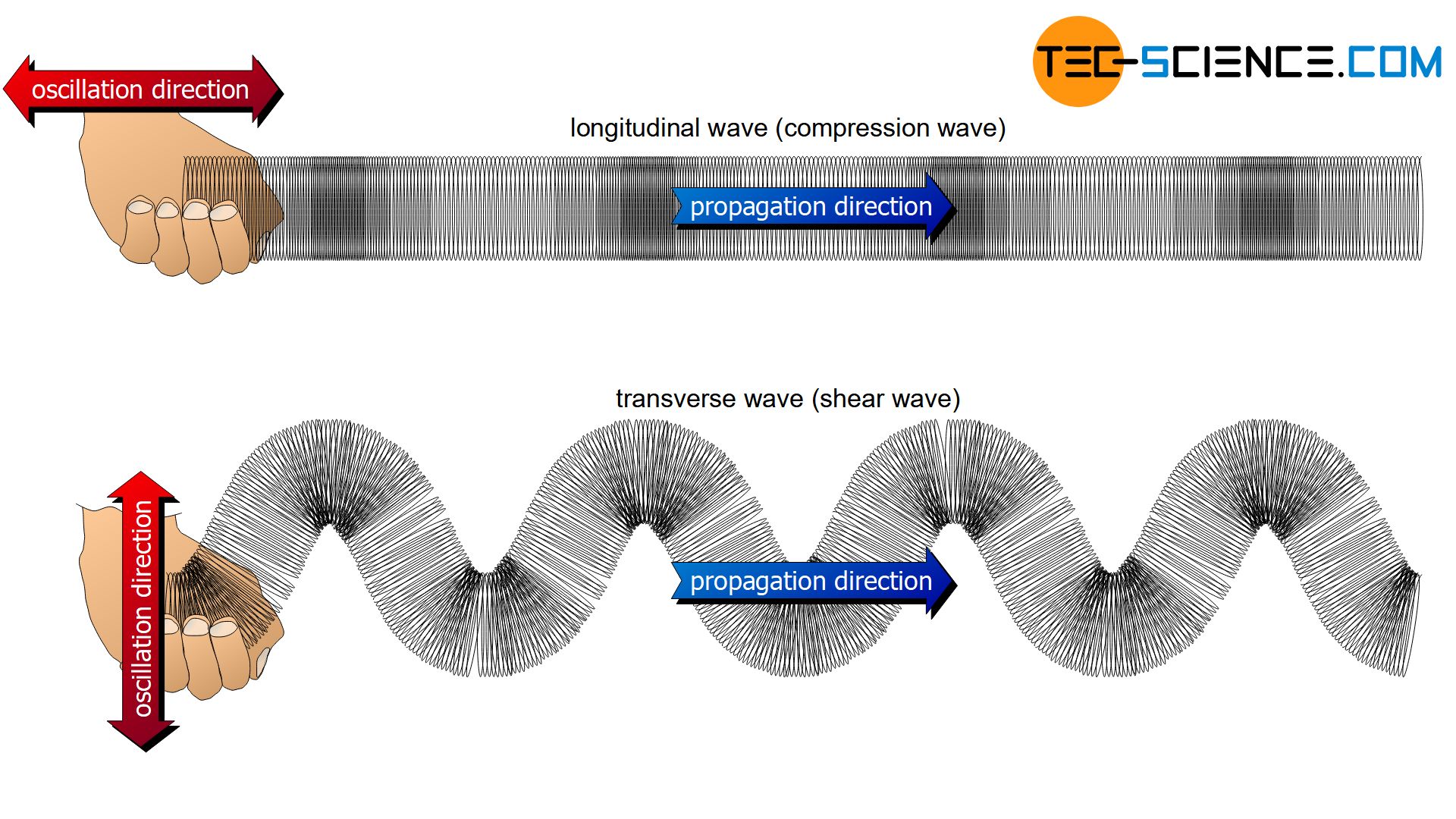
Depending on the medium, sound waves can propagate in different ways. In gaseous, liquid or solid materials, sound waves can propagate in the form of pressure fluctuations. The matter particles are compressed locally (“positive pressure”) and dilated (“negative pressure”) and transfer the corresponding impulse to the adjacent particles. The oscillation direction of the individual particles is identical to the direction of propagation of the wave. In this case one also speaks of longitudinal waves (also called compressional wave or compression wave).
In longitudinal waves, the individual particles oscillate longitudinally to the direction of wave propagation!
Besides the longitudinal wave propagation, there is another possibility of sound propagation in solids. In addition to compaction or dilution, the material can also undergo a “lateral” displacement (analogous to the swinging up and down of a rope). Such a lateral displacement has an effect on the adjacent particles, which also experience a force directed sideways and are thus gradually made to oscillate. In this case, the oscillation direction of the individual particles is perpendicular to the direction of the wave propagation. Such a wave is referred to as s a transverse wave (shear wave).
In transverse waves (shear waves), the individual particles oscillate transversely to the direction of wave propagation.
Transverse waves can only propagate in media in which the individual particles are elastically connected to their neighboring particles by binding forces. Only then can the individual particles “entrain” the neighbouring particles as they move up and down. Consequently, this only applies to solids, as there are sufficient intermolecular binding forces compared to liquids and gases.
In solids, sound can propagate both as longitudinal wave and as transverse wave; in liquids and gases, however, only as longitudinal wave.
The propagation velocity of a sonic wave is called speed of sound. The speed of sound depends primarily on the medium in which the sound propagates. The velocity at which the individual particles oscillate back and forth (called particle velocity) has no influence on the propagation velocity of the wave. The particle velocity only determines the frequency of the sound wave. However, this does not cause the wave to propagate faster or slower. Strictly speaking, the speed of sound also depends on the temperature of the medium. In the case of solids, it must also be taken into account whether the sound wave propagates as longitudinal or transversal wave.
The speed of sound depends mostly on the medium in which it propagates!
Ultrasonic probes
The principle of emitting and receiving ultrasonic waves is technically implemented in ultrasonic probes. Different probes have developed depending on the application. The most important ones will be discussed in more detail in the following sections.
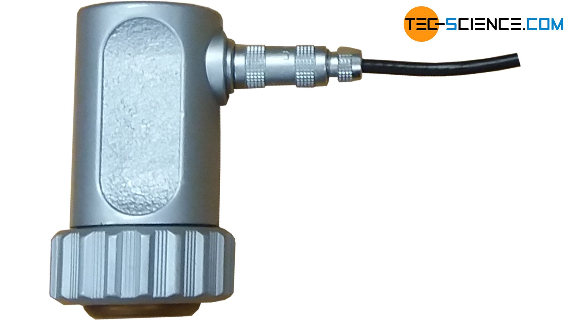
Normal probes
The simplest type of probes are so-called normal probes. These probes have only one single piezoelectric element (transducer), which is switched alternately as transmitter and receiver.
During the emission of an ultrasonic pulse, reception is basically not possible. Only when the ultrasonic pulse has been fully transmitted, the piezoelectric element can be switched back to the receive mode after a short damping period of the oscillating piezoelectric crystal. During this period of time, the emitted ultrasonic pulse has already propagated in the test material and may have already been reflected at imperfections. However, the probe could not receive these reflected waves at all, since the probe was not yet switched to “receive mode”.
This period of time within which no signal can be received is also referred to as dead time. The dead time is composed of the transmission time of an ultrasonic pulse and the damping time until the oscillations of the piezoelectric crystal have settled before the probe can be switched to receive mode. In connection with the speed of sound, the dead time results in a so-called dead zone below the workpiece surface. Imperfections within this dead zone cannot be detected by the probe.
Normal probes alternately transmit and receive ultrasonic waves; they are not suitable for testing near-surface imperfections due to the resulting “dead zone”!
To keep the dead zone to a minimum, the probe should switch to receive mode as quickly as possible after emitting the ultrasonic pulses. For this the vibrating piezoelectric crystal must be strongly damped after the emission. For this reason, a damping block (backing) is located at the rear of the crystal, which stops the vibrations as quickly as possible after the emitting pulse. At the same time, oscillations of the entire probe (due to sound waves radiated from the rear of the piezoelectric element) is avoided.
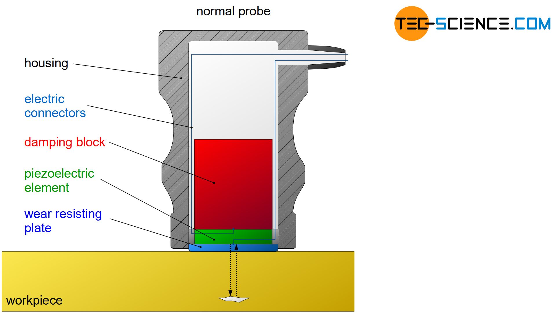
As mechanical protection, the piezoelectric crystal is separated from the workpiece surface or from the applied coupling agent by a wear resisting plate. This protection layer prevents damage to the piezoelectric element during ultrasonic testing. In addition to the coupling agent, the wear resisting plate itself provides good sound coupling to the workpiece. Probes for smooth workpiece surfaces are usually equipped with harder (more wear-resistant) protective layers, while for rough surfaces rather softer (less sound dissipative) protective layers are used.
Delay line probes
The normal probes cause a relatively large dead zone just below the workpiece surface. However, a high resolution near the surface is indispensable when inspecting near-surface imperfections or when measuring layer thicknesses.
For this reason, probes can be equipped with an integrated delay line that largely shifts the dead zone out of the test material. In this context one also speaks of delay line probes oder delay line transducers. The delay line is made of sound-conductive plastic. A matching layer is located between the piezoelectric element and the delay line. This ensures good sound transmission with good damping properties at the same time, so that a separate damping block can often be omitted.
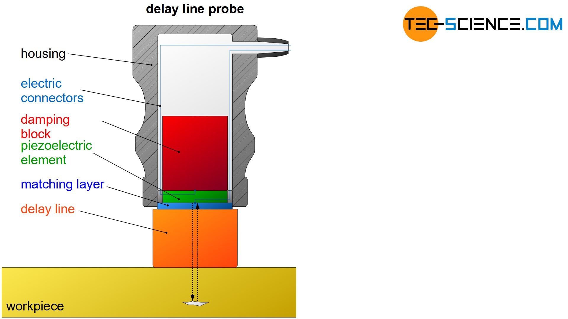
Delay line transducers have an integrated delay line within which the “dead zone” is shifted out of the workpiece surface and thus also near-surface imperfections can be detected!
When using delay line probes, reflections always occur when the emitted beam enters or leaves the the delay line. This can lead to unfavorable signal overlaps with a possible flaw echo. For this reason, the TR-probes described below have been developed.
Transmitter-Receiver probes (TR probes)
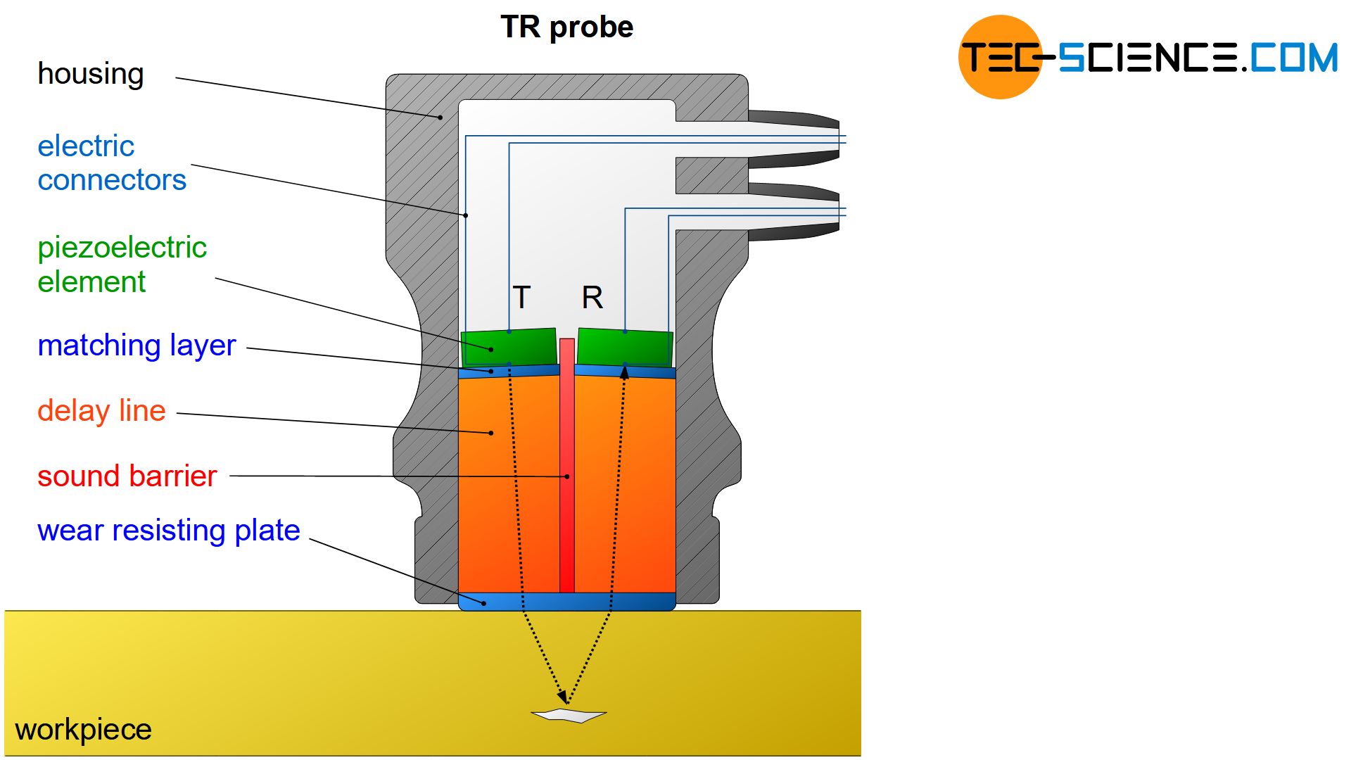
In Transmitter-Receiver probes (TR probes for short), transmitter and receiver are integrated at once and acoustically separated from each other by a sound barrier. These probes can be used to transmit and receive simultaneously by separate control units. Due to the acoustic barrier, the transmitting pulse does not leave a disturbing echo for the receiver from the delay line. This enables the detection of near-surface imperfections and the measurement of thin wall thicknesses.
So that a flaw echo does not occur at the transmitter but can be detected at the receiver, the sound pulse must be radiated slightly obliquely into the workpiece. This is the only way that the flaw echo can reach the spatially separated receiver again at an angle. For this reason, the transmitter and receiver are slightly tilted towards each other. However, a dead zone forms, within which the flaw echoes are reflected past the receiver. The more the transmitter and receiver are tilted, the smaller the dead zone becomes, but deeper imperfections cannot be resolved as well.
The depth of the maximum resolution lies at the intersection of the acoustic axes of the transmitter and receiver. This is where the measurement sensitivity is greatest. At a relatively steep inclination, the greatest measurement sensitivity is therefore very close to the surface and the dead zone is relatively small. However, due to the small overlap of the sound paths, the sensitivity decreases considerably at deviating depths. A good resolution over longer distances can be achieved by smaller angles of inclination, but this increases the dead zone.
Transmit-Receive probes (TR probes) can transmit and receive ultrasonic waves simultaneously. Depending on the inclination of transmitter and receiver, the measurement sensitivity can be optimized to a certain depth!
When determining the flaw depth, it should be noted that TR probes cause a V-shaped sound path in the workpiece. The sound path and propagation time of the ultrasonic signal are therefore greater for TR probes than for normal probes. Furthermore, it should be noted that, due to the inclined intromission of sound, refraction occurs at the interface to the test material, i.e. the incident beam changes its direction as soon as the sound wave enters the workpiece (refraction is a general phenomenon of waves when penetrating a medium with a changed propagation velocity)!
Angle probes
The inspection of weld seams requires an oblique intromission of sound so that the interface between weld seam and base material can be examined for cracks. For this reason, angle probes were developed which radiate the sound waves into the workpiece at a certain angle. Frequently used intromission angles are 45°, 60° and 70°.
Angle probes are particularly suitable for the inspection of weld seams due to the oblique scanning!
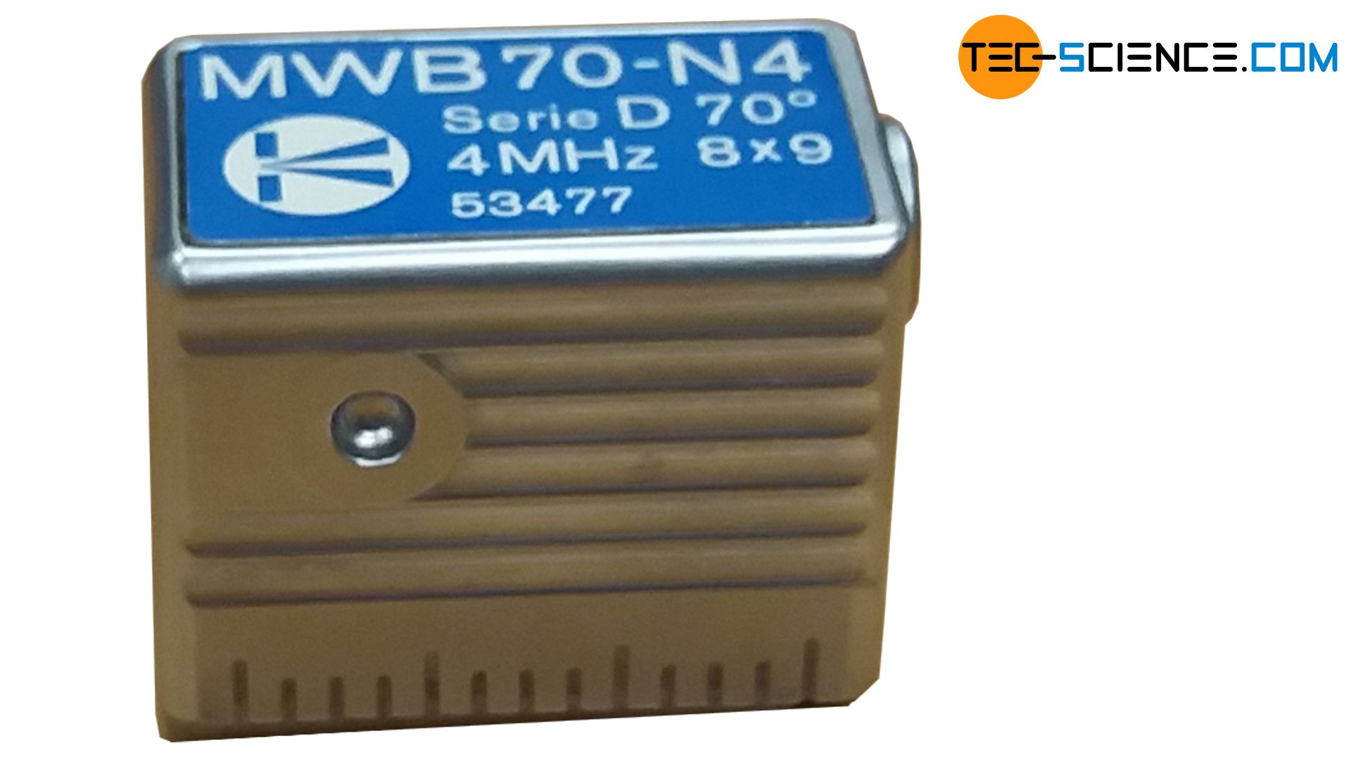
In general, angle probes are equipped with delay lines, which are then also referred to as delay wedges. Angle probes can also be equipped with TR probes, so-called angle transmit-receive probes (angle TR probe).
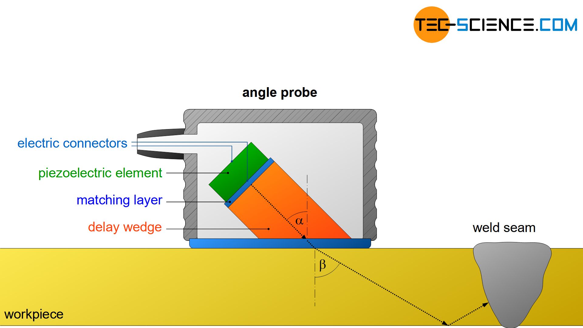
In addition, a change in angle by refraction is connected to the inclined intromission of sound. Since the emitted sound waves usually propagate slower in the delay wedge (or in the wear resisting plate) than in the workpiece, a refraction away from the normal of the boundary takes place. Furthermore, the sound wave no longer propagates as a longitudinal wave but as a transverse wave. The longitudinal wave component is totally reflected at the boundary due to the greatly differing propagation velocity.
Phased array probes
Phased array probes are basically made up of a multitude of individual transducers. Such probes are therefore also referred to as group transducers. In a group there are e.g. 16, 32, 64 or more oscillators. The individual transducers can be controlled separately in time. This allows a wide range of applications since the transmission characteristics can be specifically influenced. Phased array probes can only be used with special testing devices that have the appropriate software and hardware to control the probes.
Phased array probes contain a large number of individually controllable transducers. This allows the transmission characteristic to be specifically influenced!
The basis for influencing the transmission characteristic is Huygens principle, which states that the envelopes of the individual ultrasonic waves form the new wave front.
The animations below show different timing controls. If the transducers are controlled one after the other, an angular acoustic irradiation is obtained. The sound field can also be permanently swivelled during the test. The flaw (also called discontinuity) then becomes visible at different angles and allows a limited indication of the flaw size. This is usually not easily possible with simple probes.
Furthermore, with phased array probes the ultrasonic waves can be focused to a certain depth. The focus can also change over time, so that it moves permanently through the test sample.
Advantages, disadvantages and limitations of ultrasonic testing
Ultrasonic testing is not only used for detecting flaws but also for wall thickness measurement or for measuring the layer thickness of components subject to wear. It is particularly important for weld seam inspection by using an angle probe. Ultrasonic testing can be easily automated and, in comparison to the X-ray process, carried out without protective equipment. Test depths of several meters are theoretically possible depending on the acoustic properties of the test sample.
In addition to the flaw detection, ultrasonic testing also takes place for wall thickness and layer thickness measurements!
Although the position of a flaw can be determined very reliably with ultrasonic testing, the flaw size cannot be determined easily. A laminar flaw should be scanned as perpendicular as possible in order to be able to resolve it optimally. In order to estimate at least the approximate flaw dimension, the flaw should be scanned from different angles. The resulting flaw echo can then be compared with the echoes of reference flaws. Phased array probes can perform this function of the different beam angles to a limited extent. However, such a comparison method does not provide a 100% reliable statement.
Depending on the spatial orientation of the flaws, they are difficult to detect. Likewise, the flaw size is usually not clearly determinable!
The resolution of possible flaws is limited depending on the ultrasonic frequency used. Flaws that are smaller than half the wavelength of the ultrasonic pulses can no longer be physically resolved. As the wavelength decreases with increasing frequency, smaller flaws can therefore only be resolved by higher sound frequencies. However, the higher the frequency, the higher the sound absorption, so that the high-frequency ultrasonic pulses may not be able to reach deeper flaws.
Only flaws that are larger than half the wavelength of the ultrasonic waves can be physically resolved!


")
")
")